¶ What it is?
The Chamber Temperature Regulator Fan is responsible for adjusting the temperature within the chamber. The fan operates based on the detected chamber temperature, determining both its on/off status and the speed at which it operates.
.png)
¶ When to use
If a warning regarding the regulator fan appears on the display screen and after checking the connection and environment, everything seems to be in order.
¶ Tools and materials needed
- A new chamber temperature regulator fan
- H1.5 & H2.0 Allen key
- Tweezer
¶ Safety warning and Machine state before starting operation
Before proceeding with the steps outlined in this guide, ensure that the machine is switched off, and remove the AMS, PTFE tube, and filament buffer.
¶ Video Guide
¶ Operation Guide
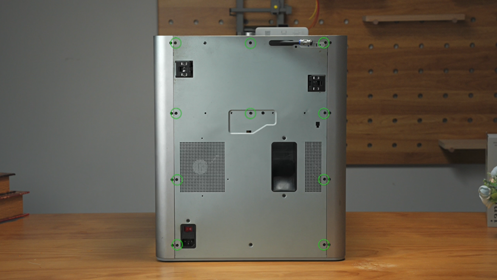
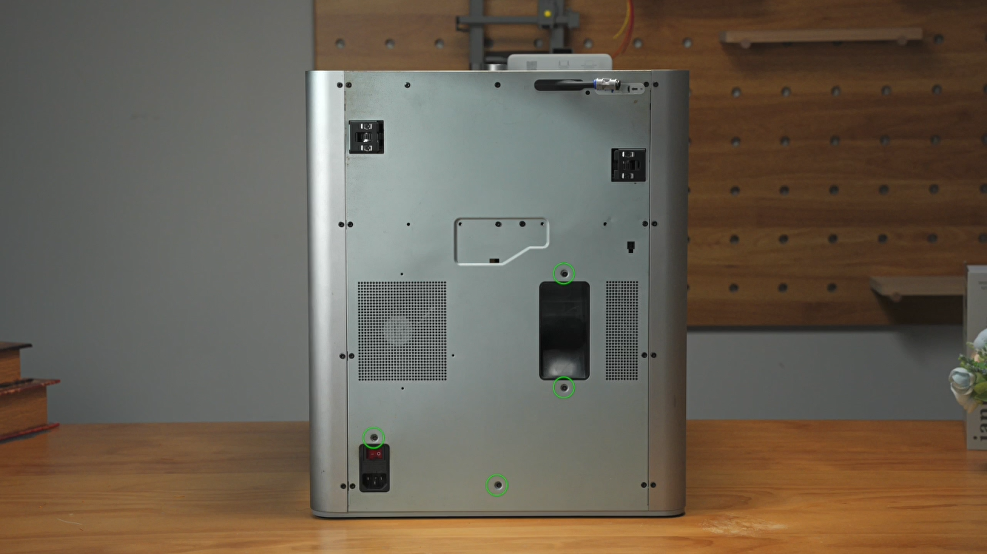
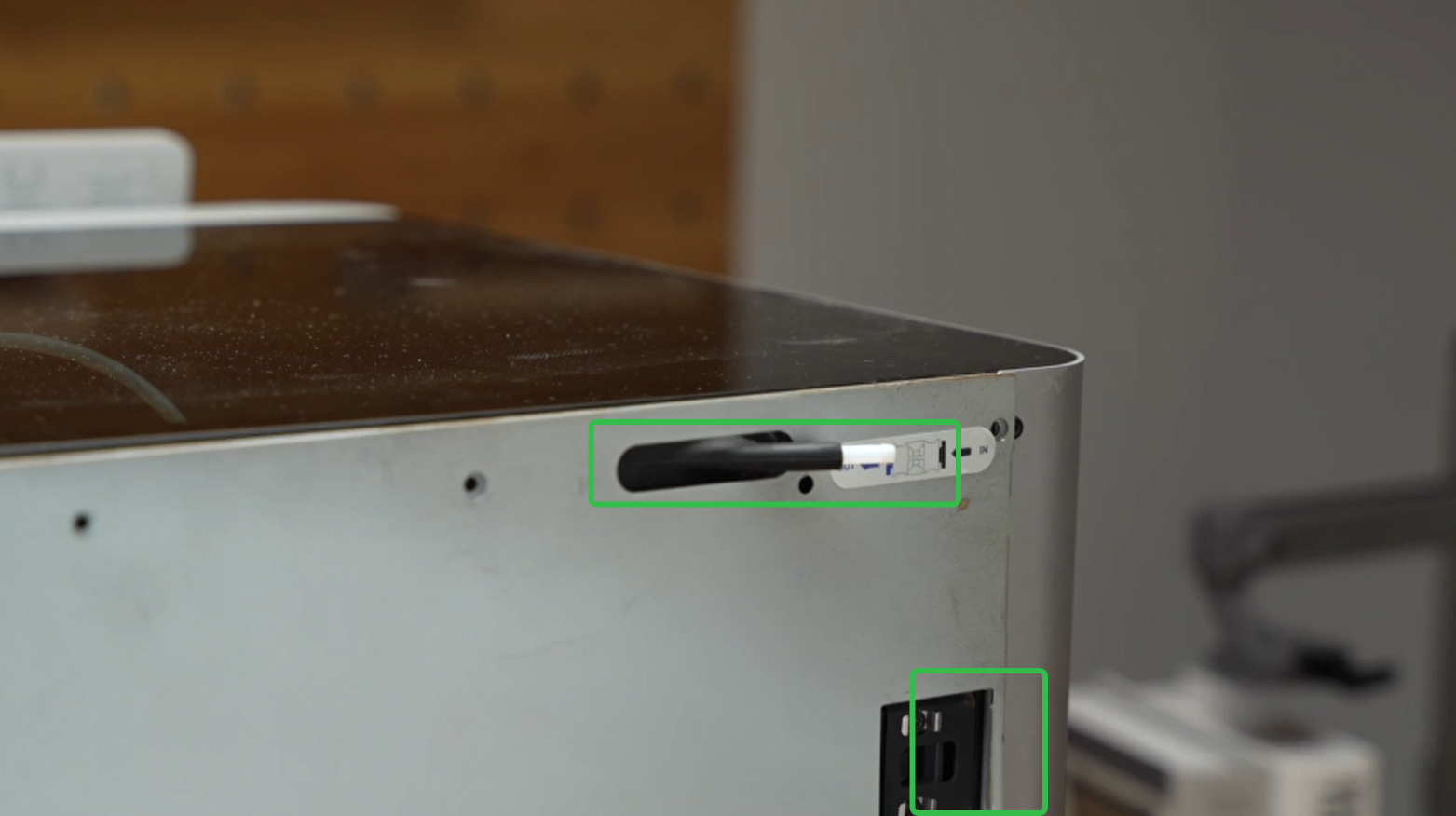
¶ Remove the rear cover
- Loosen the screws at the back of the printer. There are a total of 14 screws to be undone—10 in the first image and 4 in the second image, as indicated below.
 |
 |
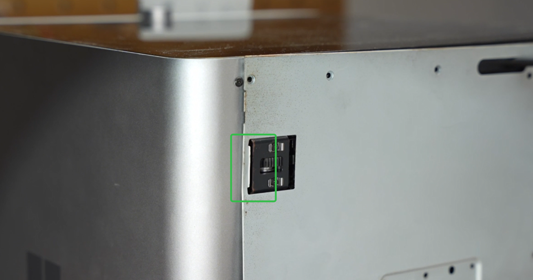
- Remove the PTFE tube coupler.
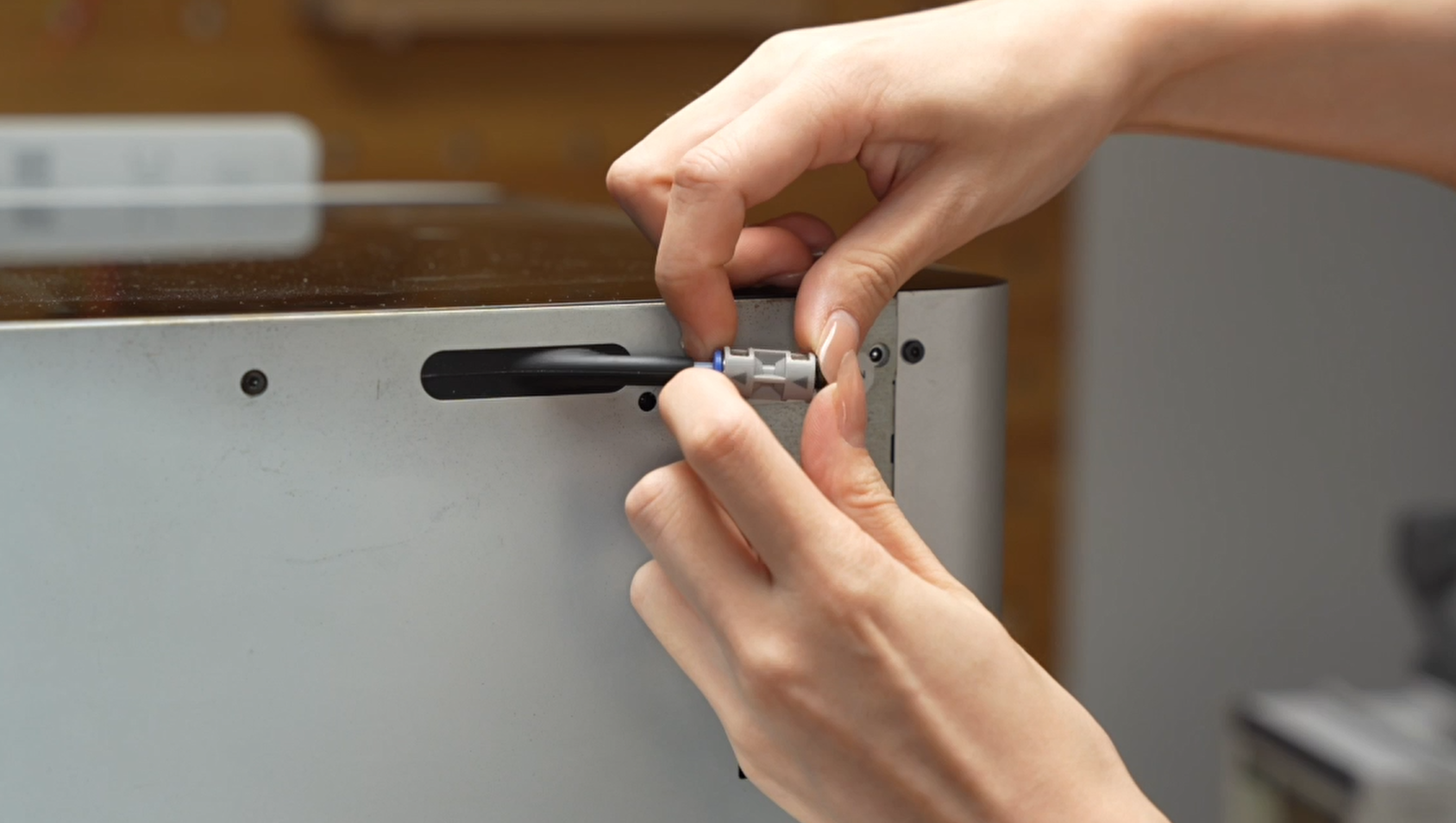
- To remove the rear cover, start by pulling the left side to prevent interference with the left belt tension port, and then proceed to the right side. Push the PTFE tube outlet inwards to release it from the cover.
 |
 |
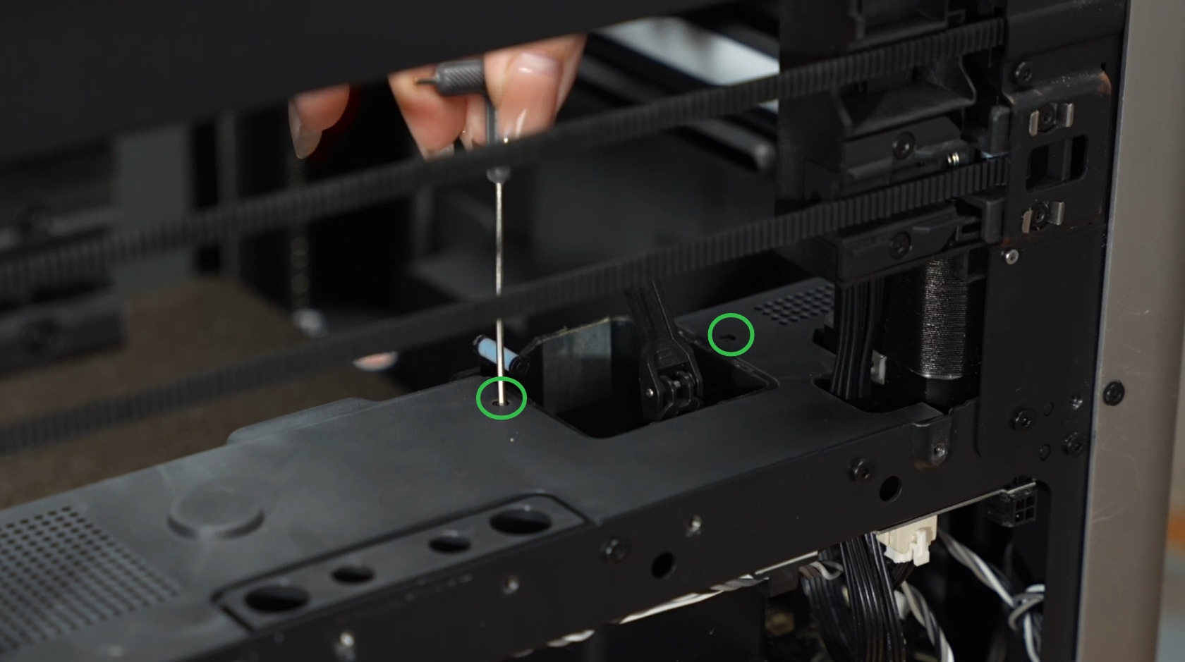
¶ Remove the purge chute
Loosen the 2 screws (3 on newer versions) located on each side of the purge chute. Once completed, remove the purge chute.
 |
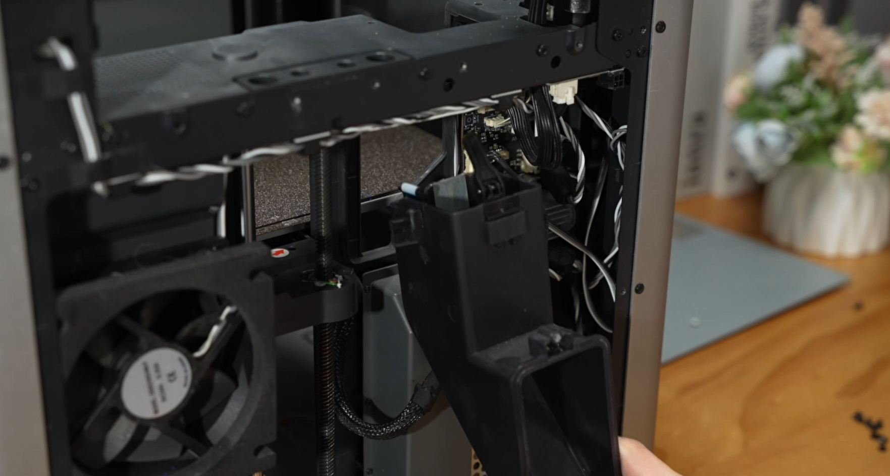 |
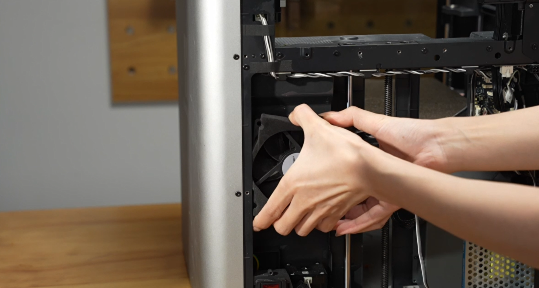
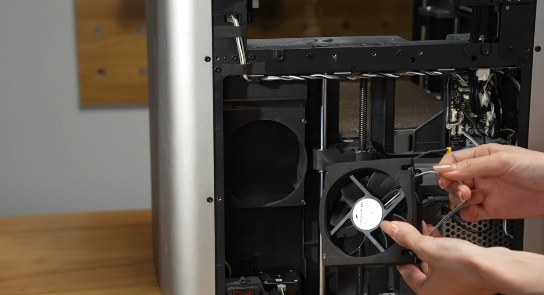
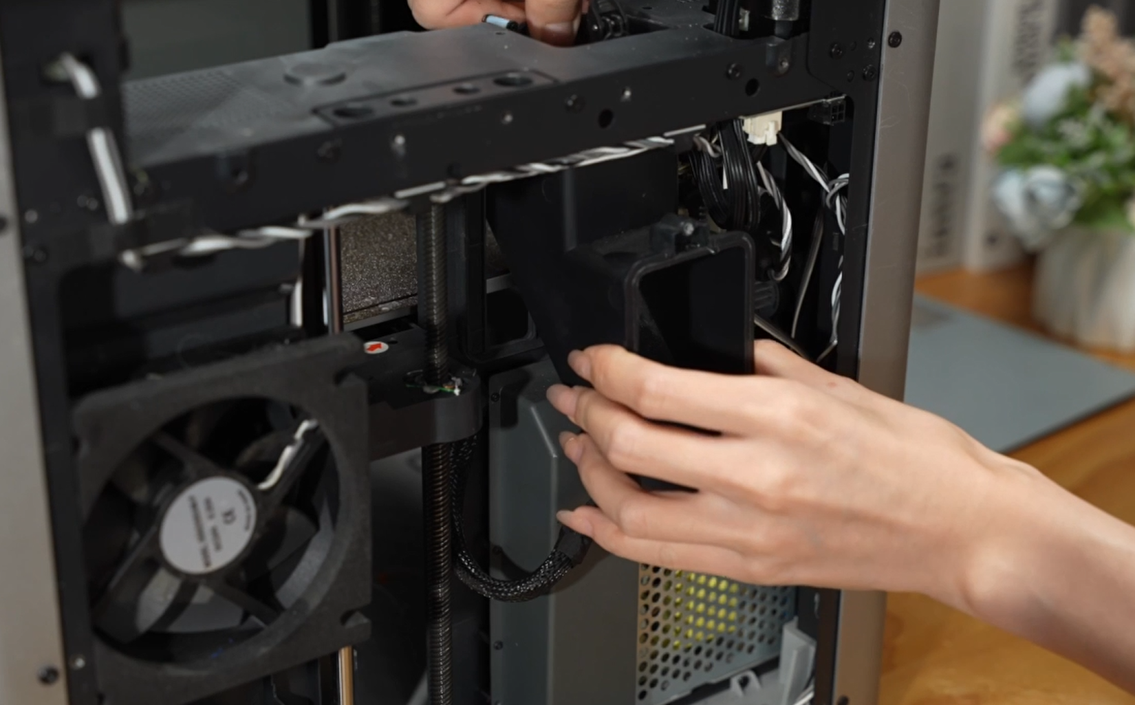
¶ Remove the chamber temperature regulator fan
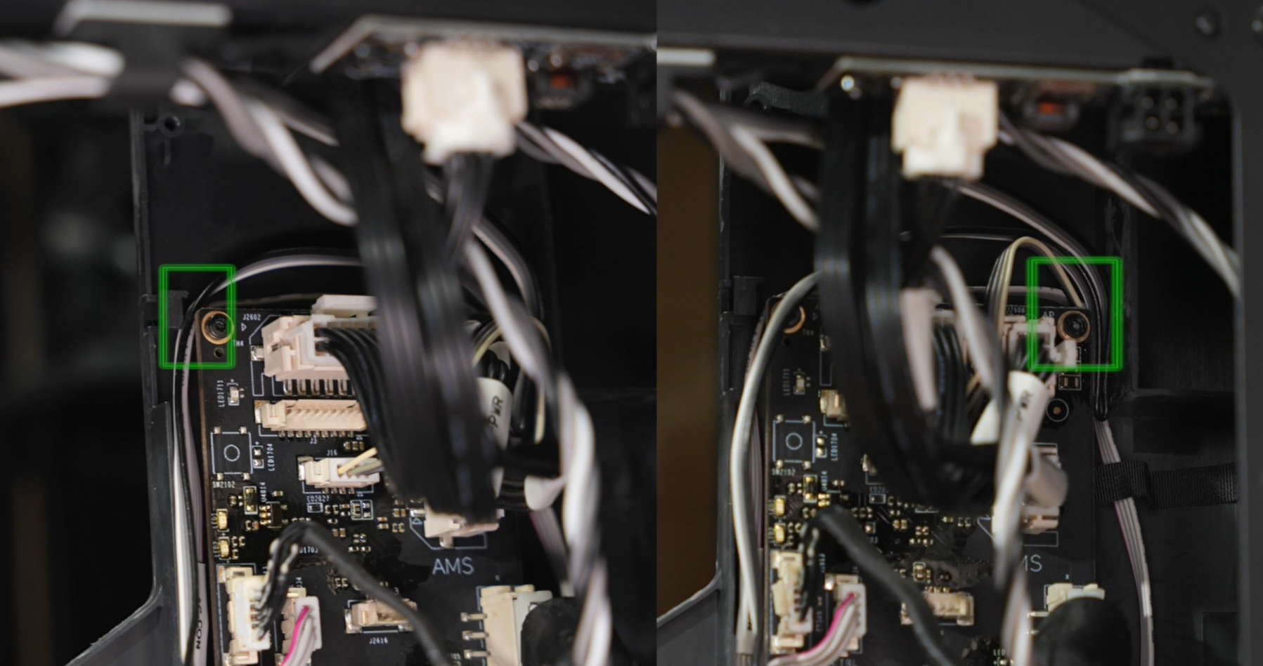
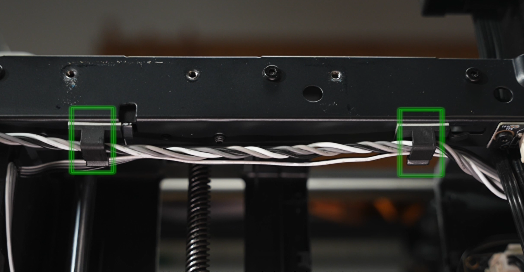
- Disconnect the cable from the connector on the Machine Controller (MC) board, and release the fan cable from the cable clips.
 |
 |
 |
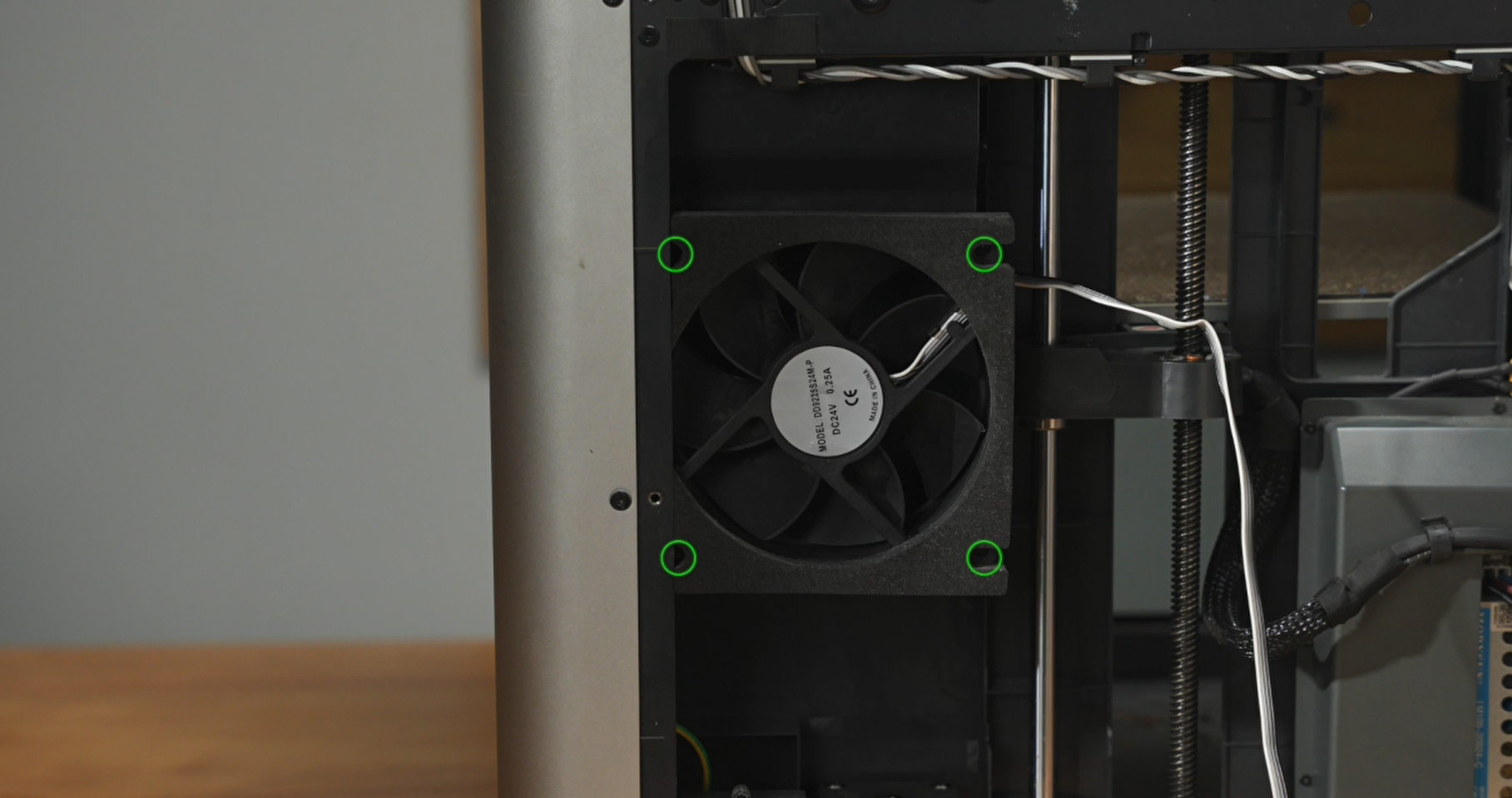
- Take out the 4 screws securing the fan in place. It's recommended to use a tool like tweezers to hold the screws from the back in case they fall off.
 |
 |
- Remove the chamber temperature regulator fan.
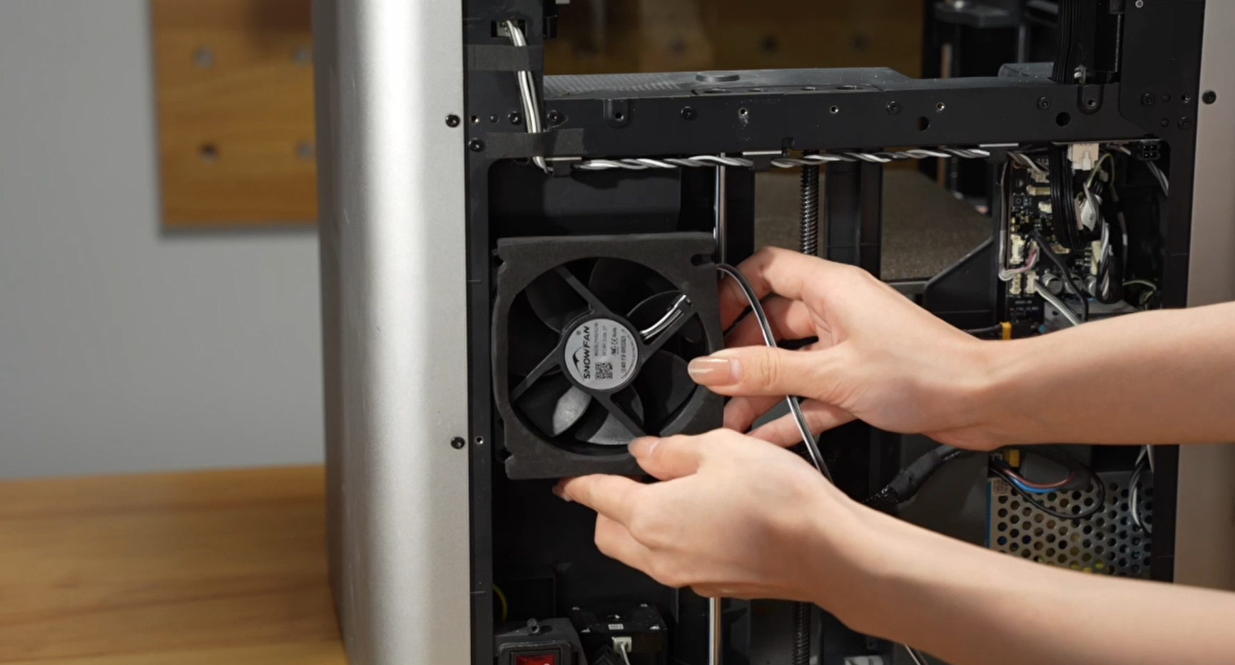
¶ Install the new fan
- Remove the cable of new fan from its cable clips.
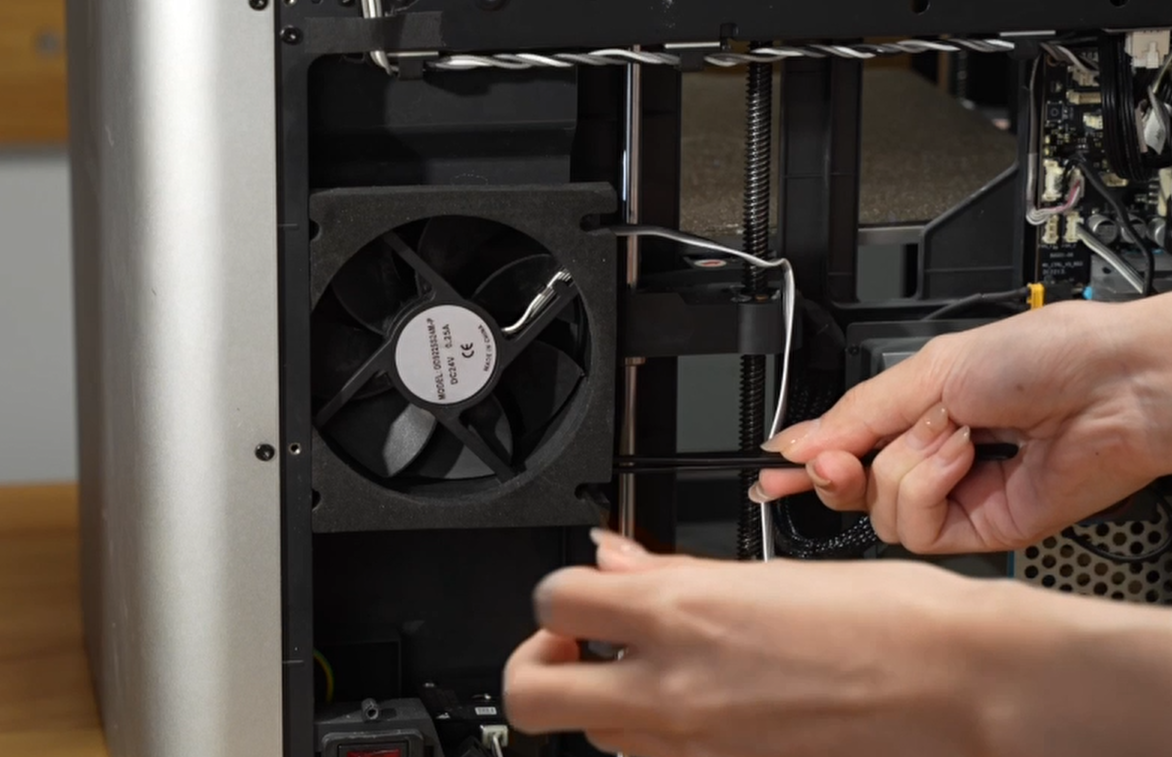
- Use the 4 screws to secure the fan in place. Remember to use tweezers to hold the screws and lock them in position.
 |
|
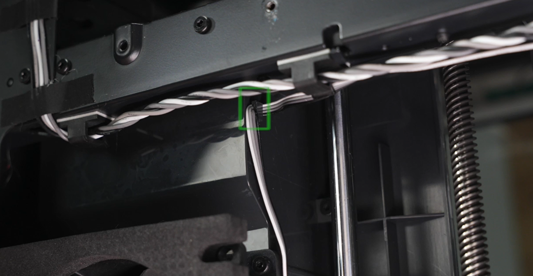
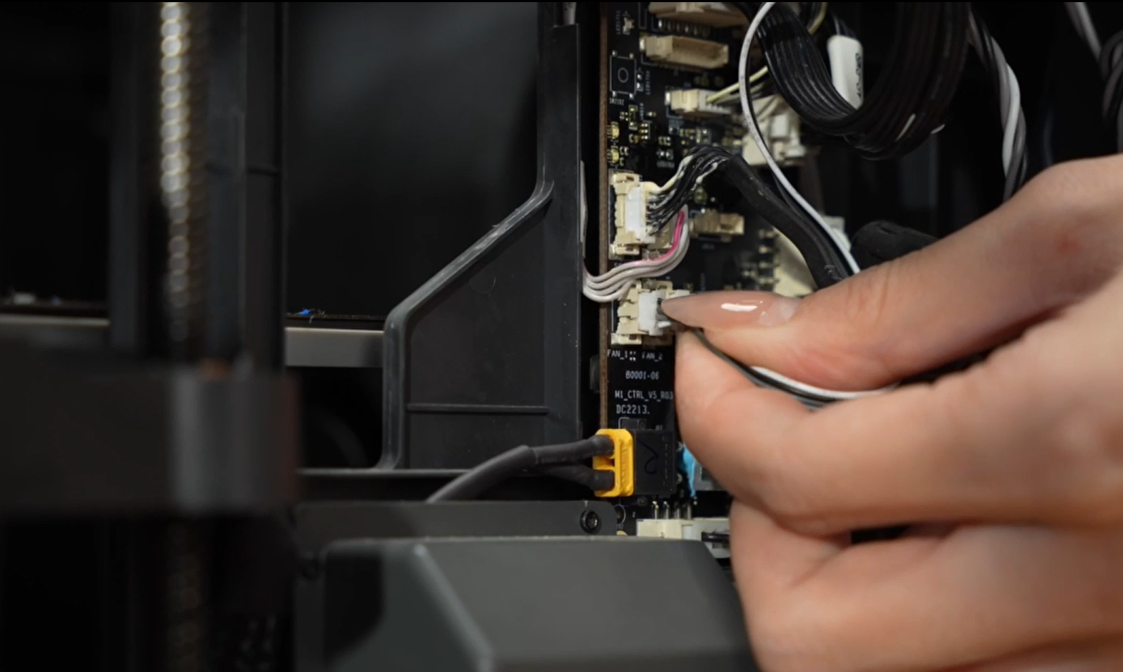
- Route the fan cable through the cable clips along the frame and the MC board as shown below. Then connect the cable to the MC board.
|
|
 |
¶ Install the purge chute
Install the purge chute by sliding it back into its position, paying attention to the protruding tabs on both sides of the chute. Finally, secure it in place with 2 screws (3 on newer versions) on each side at the top of the chute.
 |
|
¶ Install the rear cover
- Start by passing through the tube bracket, then secure the right side of the rear cover beyond the right belt tensioner, as shown below. Follow this by securing it past the left belt tensioner.
|
|
- Screw the rear cover back on, paying attention to the different types of screws (10 and 4) as pointed out earlier.
|
|
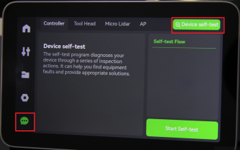
¶ To verify completion/success
Connect the power cord and turn on the power. Proceed to run a device self-test operation as indicated below. If no errors occur during the self-test, the replacement can be considered successful.
If you encounter any issues, start by retracing your steps and checking all connections. Attempt the process again. If problems persist or you need further assistance, please contact the service teamfor further assistance.
¶ End Notes
We hope the detailed guide provided has been helpful and informative.
To ensure a safe and effective execution, if you have any concerns or questions about the process described in this article, we recommend submitting a technical ticket regarding your issue. Please include a picture or video illustrating the problem, as well as any additional information related to your inquiry.