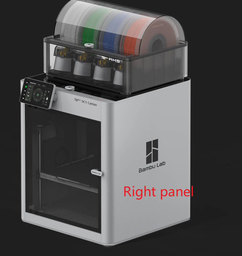
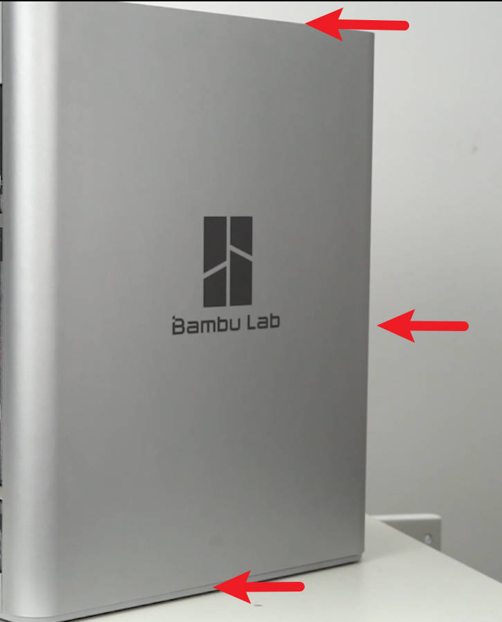
¶ What is the right panel
When facing the printer's front door, the right side cover is referred to as the right side panel. The X1C utilizes a metal panel.
¶ When to use
Unacceptable deformation or damage on the right panel
¶ Tools and materials required
- A new right panel
- H2.0 hex key
¶ Safety warning and Machine state before starting operation
Before commencing the operation, ensure that the machine is switched off. If an AMS is connected, remove the PTFE tube and AMS buffer before proceeding.
Please also check the Old version information in this guide, if your printer uses the previous way of attaching the panel to the printer
¶ Operational guide(New version)
¶ Video guide
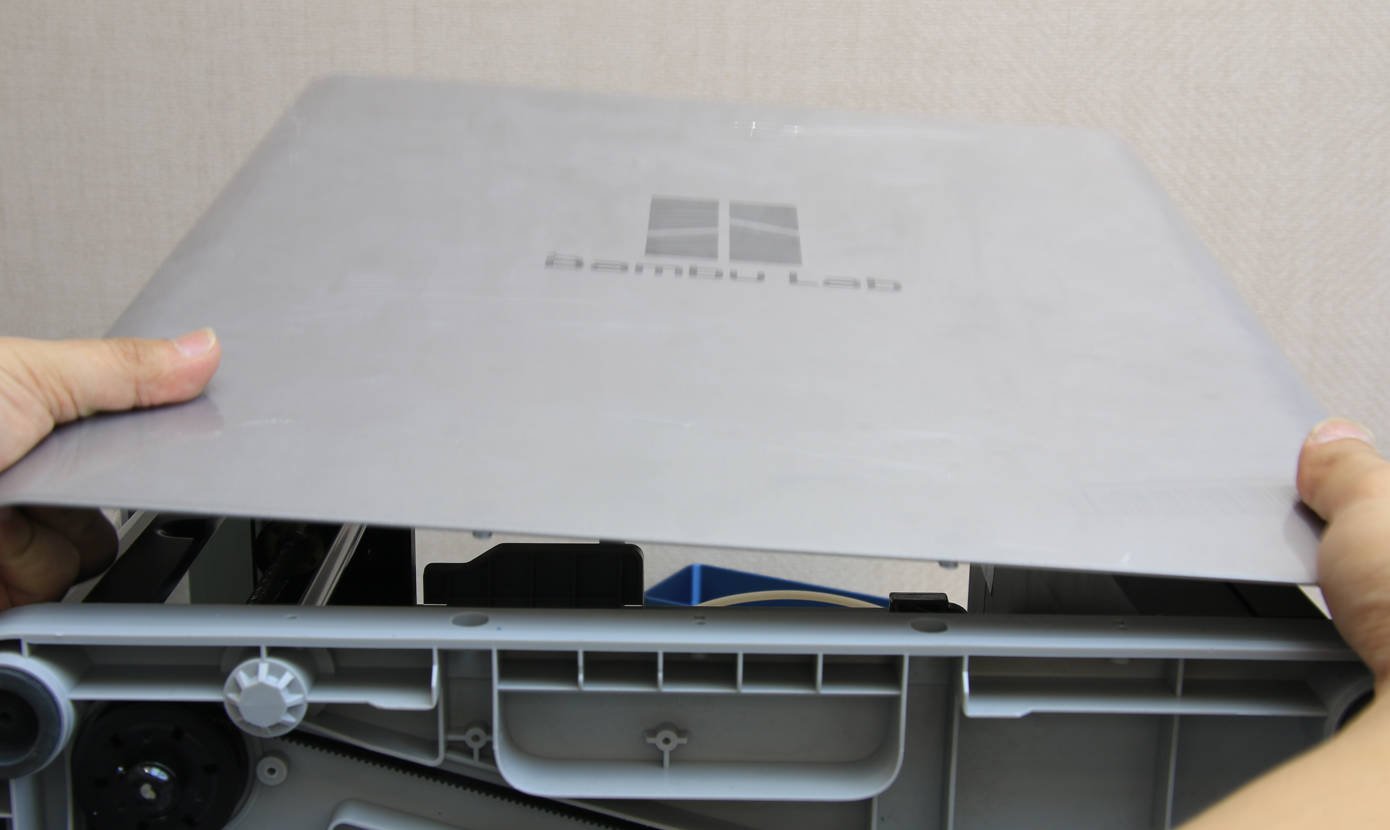
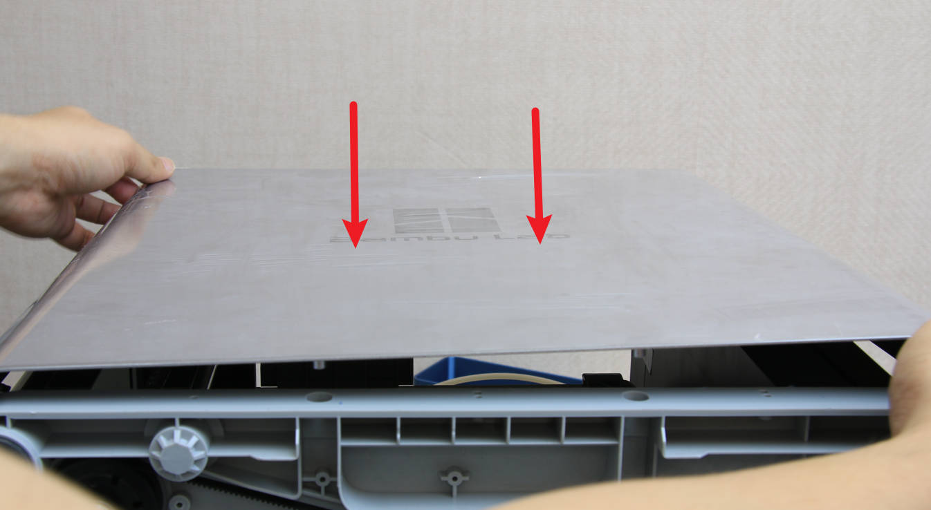
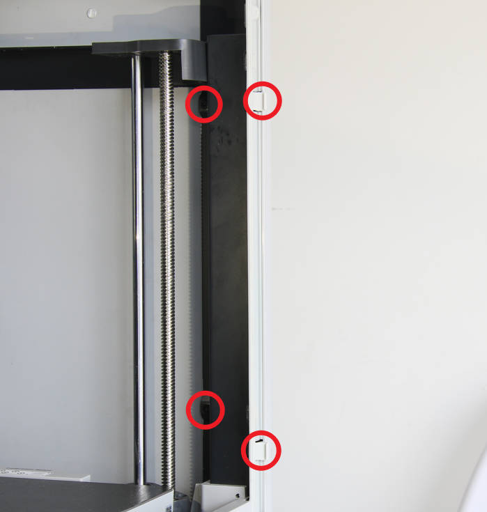
¶ Step 1 - Remove the front pillar screws
Remove the upper glass cover plate, open the front door, and remove the 4 screws on the front pillar with the H2.0 hex key.
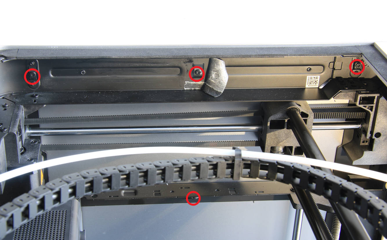
¶ Step 2 - Remove rear screws
Remove the 4 screws on the rear part of the panel using the H2.0 hex key.
¶ Step 3 - Remove the screw on the upper beam
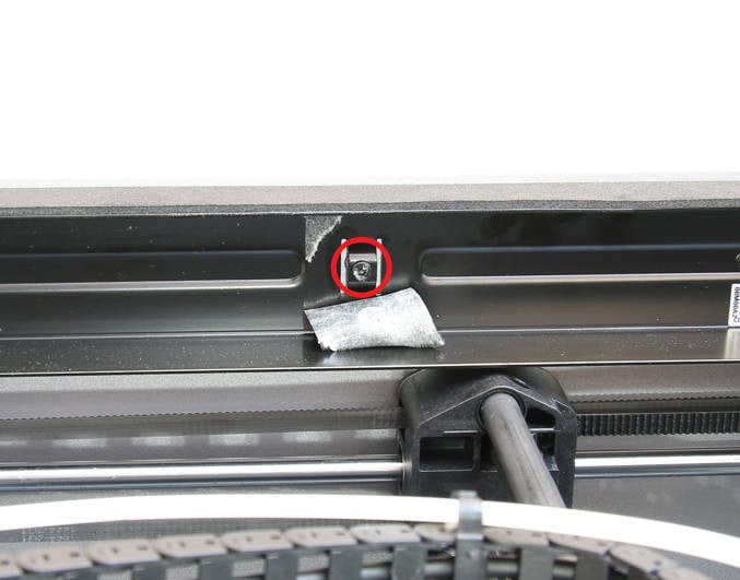
Remove the EVA pad located in the middle of the upper beam, and then use an H2.0 hex key to remove one screw.
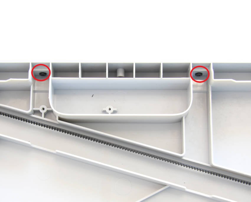
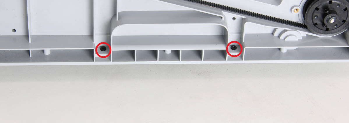
¶ Step 4 - Remove the bottom screws
Place the printer on its side, with the right panel facing up, and remove the 2 screws using an H2.0 hex key.
¶ Step 5 - Remove the right panel
Using both hands, carefully hold the right panel and remove it from the printer.
¶ Step 6 - Install the right panel
Install the right panel onto the printer, ensuring it is properly in place.
¶ Step 7 - Secure the bottom screws
Secure 2 screws at the bottom and put the printer upright.
¶ Step 8 - Secure the screw on the upper beam
Secure 1 screw in the middle of the upper beam, and attach back the EVA pad.
¶ Step 9 - Secure the front pillar screws
Secure the 4 screws on the front pillar.
¶ Step 10 - Secure rear screws
Secure 4 screws on the rear of the right panel, and place back the upper glass cover plate.
¶ Operational guide(Old version)
¶ Step 1 - Remove screws
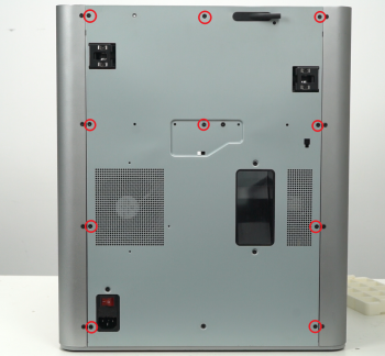
NOTE: This procedure involves a lot of screws. To prevent any issues, please ensure to label and group them into separate sections accordingly.
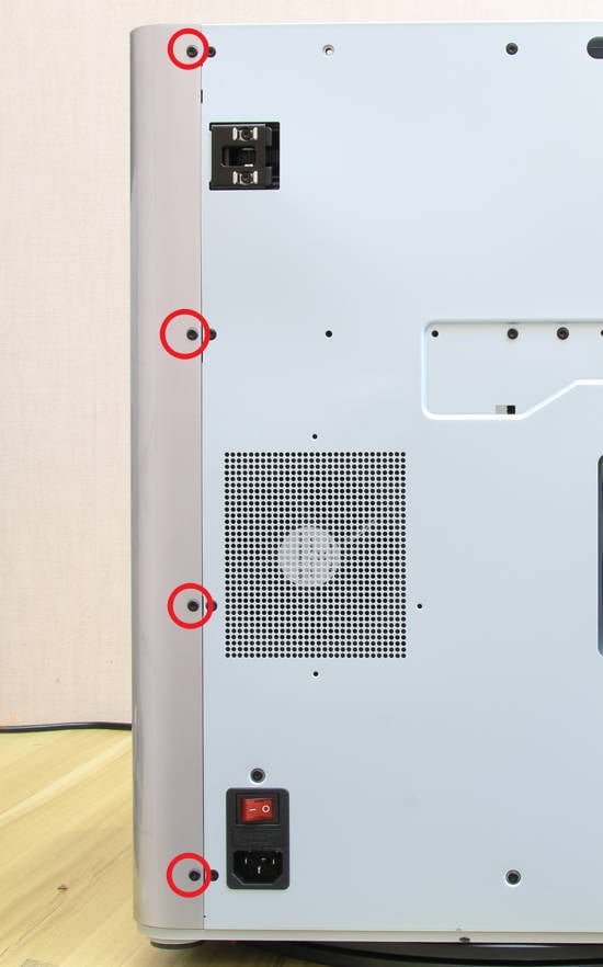
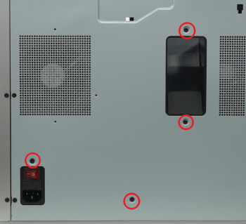
Remove the 10 screws and 4 screws from the rear cover shown in the picture. There are 2 types of screws, so keep them separate and remember which ones go where.
 |  |
¶ Step 2 - Remove the rear cover
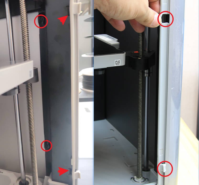
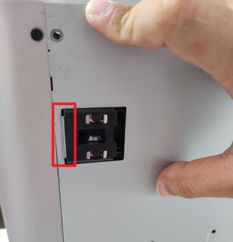
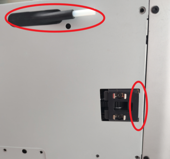
To prevent getting stuck, first unlock the left side belt tension port, followed by the right side one, before removing the rear cover.
 |  |
¶ Step 3 - Remove the right panel
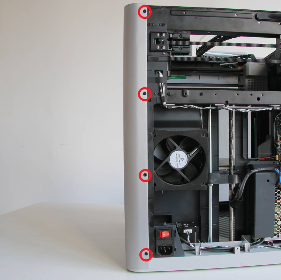
The right metal panel of the old version is fixed with a total of 16 screws, of which the 4 screws at the back are different from the other 12 screws. Refer to the picture below to find the screws in the corresponding positions and remove them one by one, then remove the entire right panel.
Note: X1 can refer to this version for processing, but the screws will be different due to different materials.
¶ Step 4 - Install the right panel
Install the right side panel to the printer, making sure it is in place.
¶ Step 5 - Secure the right panel screws
All screws should be locked according to the actual version. Please refer to the picture below for the screw-locking sequence. Note that the rear 4 screws are different from those in other positions, so don’t make a mistake.
¶ Step 6 - Install the rear cover
To install the rear cover, pass the PTFE tube through the tube bracket. Begin by installing the right side belt tension port first, followed by the left side.
.png) | 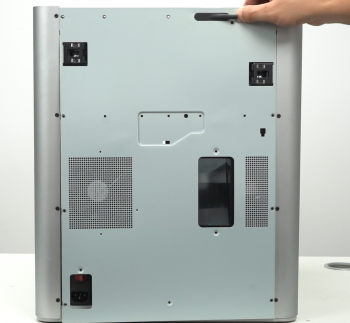 |
¶ Step 7 - Install the 10+4 screws
Install the 10 + 4 screws (see picture), and place back the top glass cover plate.
.png) | .png) |
¶ To verify completion/success
Visually check the appearance and confirm that the right panel is installed in place.