¶ What is the chamber LED
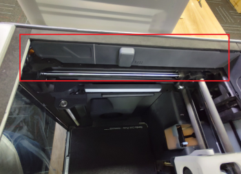
The chamber LED is an LED bar installed on the left beam of the chamber and used to supplement the light of the chamber. We provide the chamber LED bar with connecting cable.
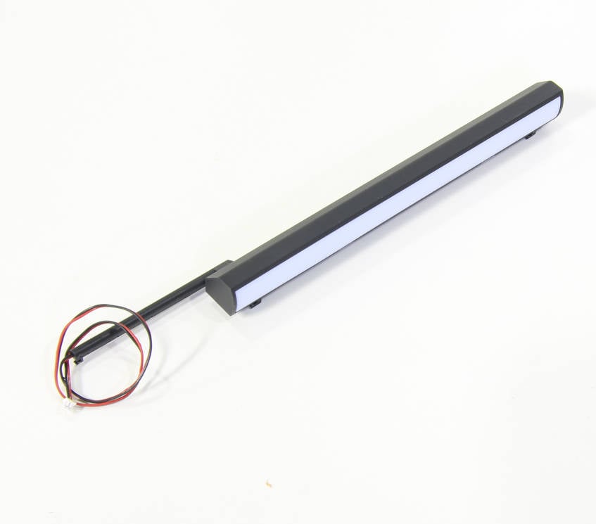
¶ When to use
1. LED burnt
2. Damaged LED light cable and short circuit.
¶ Tools and materials needed
- New chamber LED
- H2.0 hex key
- Tweezers
- Hair dryer
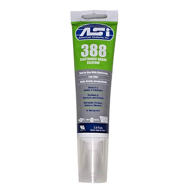
- Silicone glue
¶ Safety warning and machine state before starting operation
Before following this guide, please make sure the machine is powered off.
¶ Disassembly Guide
¶ Step 1 - Power off
Power off the printer, unplug the power cord and remove the top glass cover plate.
¶ Step 2 - Open the AP board cover
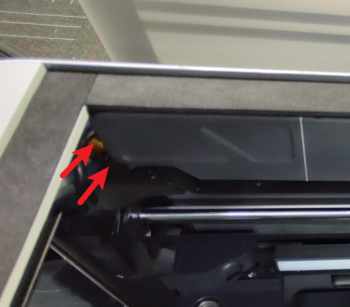
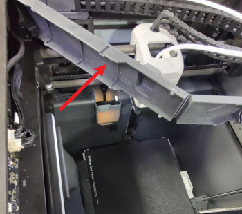
Open the AP board cover as shown in the pictures below which is located at the upper left part of the machine.
 |
 |
¶ Step 3 - Disconnect the cables
Use the hair dryer to soften up the silicon glue securing the connectors, then disconnect the chamber LED cable and the button board cable.
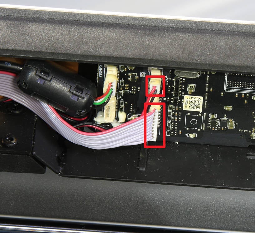 |
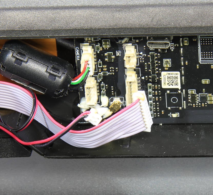 |
¶ Step 4 - Loosen the chamber camera
Push the camera as shown in the picture below to release the camera from the beam to facilitate the removal and installation of the chamber LED.
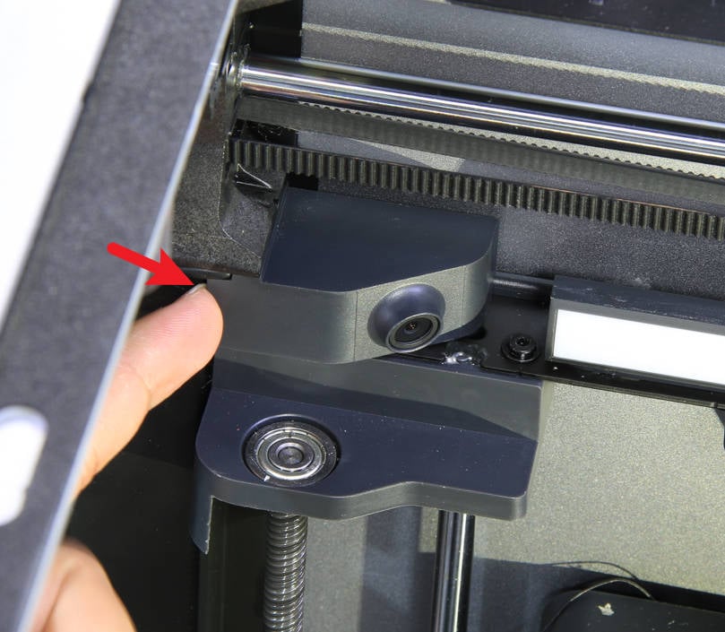 |
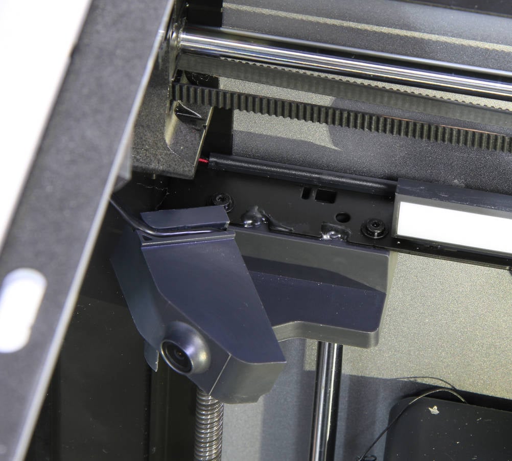 |
¶ Step 5 - Remove the LED bar
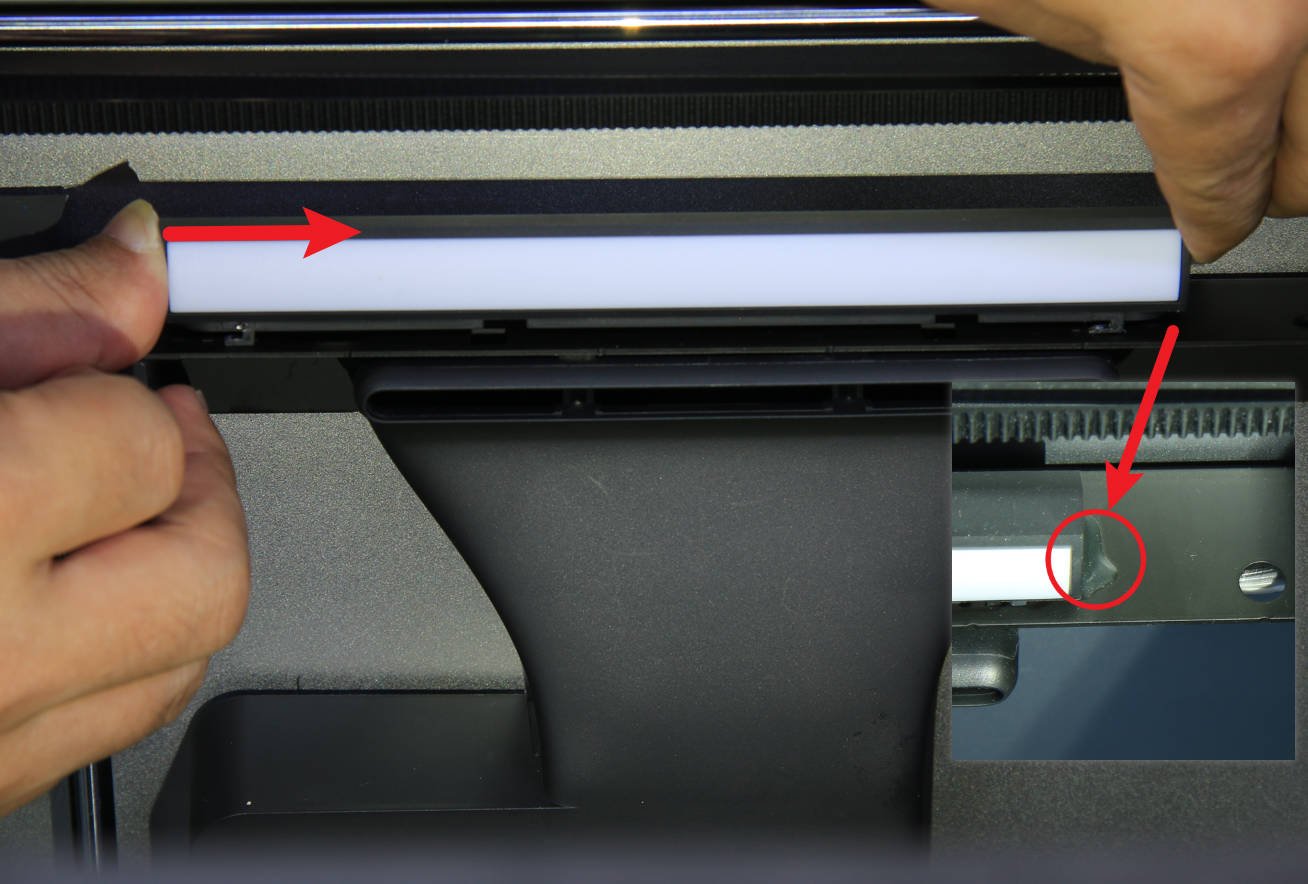
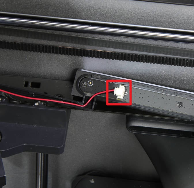
First confirm whether the end of the LED is reinforced with black glue, if so, it needs to be cleaned manually. Then push the LED bar in the direction of the arrow shown in the picture to release the LED light bar, then disconnect the cable connected to it and remove the LED bar, but leave the cable in its original position.
 |
 |
¶ Step 6 - Loosen the AP board
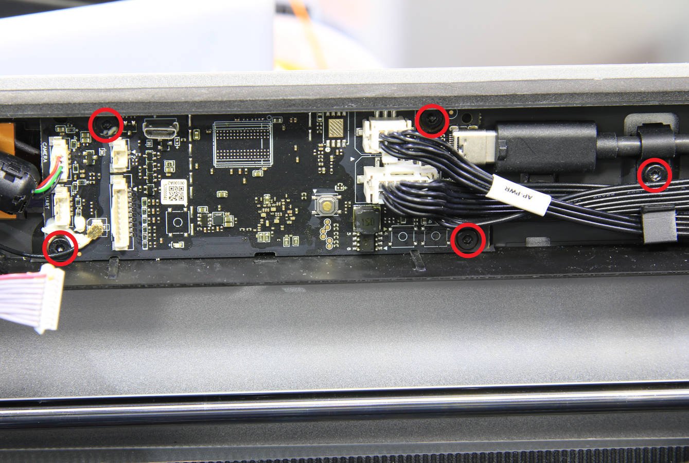
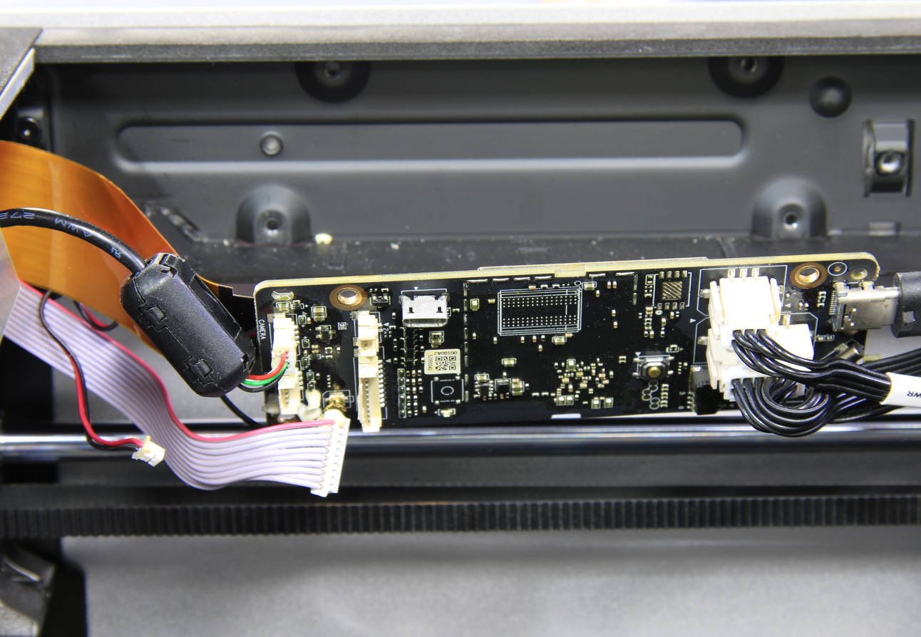
Unscrew 5 screws with an H2.0 hex key to loosen the AP board from the upper beam.
 |
 |
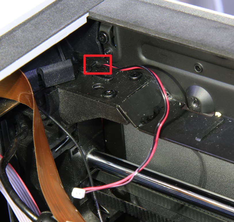
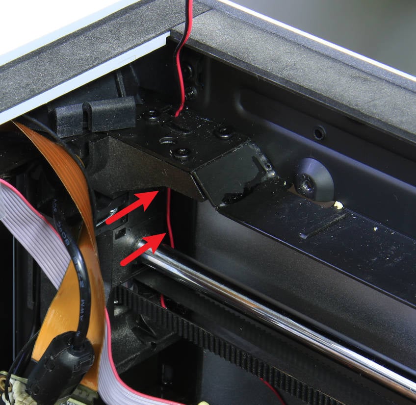
¶ Step 7 - Release the LED cable
Release the old LED cable from the gap, as it may be stuck tight and may need to be pulled out with a little force, but do not remove it from the printer yet.
 |
 |
¶ Assembly Guide
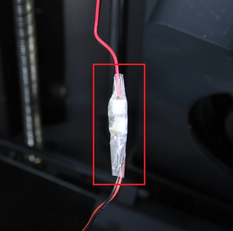
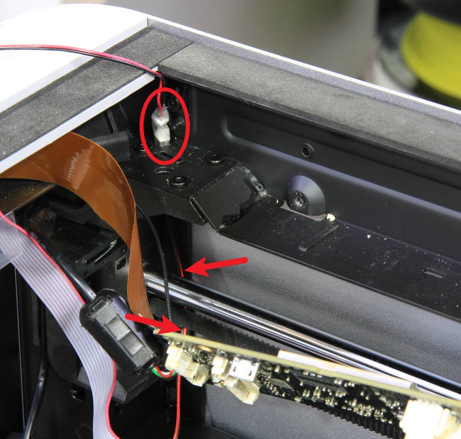
¶ Step 1 - Pass through the new LED cable
Bond the connectors of the old and new cables with tape, pay attention to the front end position, twist as thin as possible, and then use the old cable to guide the cable of the new LED through the cable hole. Be careful not to use too much force or speed when passing the cables to avoid damage to the new cable. In addition, the cable should pass between the left panel and the polished rod (and belt). Then remove the tape and old cables.
 |
 |
¶ Step 2 - Install the chamber LED
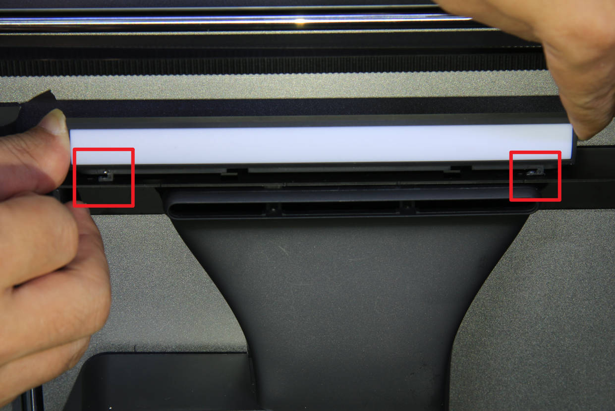
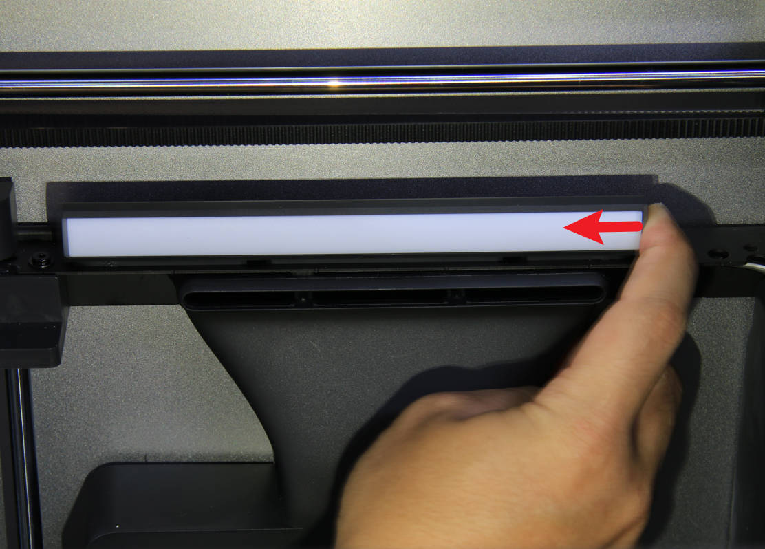
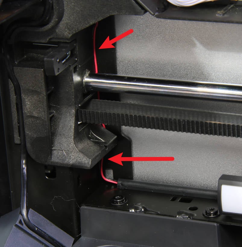
Align the claws under the LED base with the mounting holes on the beam, then push the LED bar in the direction of the arrow to install it in place. Finally, tuck the LED cable into the gap along the column and the side panel, but don't damage the cable, or just stick it to the left panel with tape.
 |
 |
 |
¶ Step 3 - Install the chamber camera
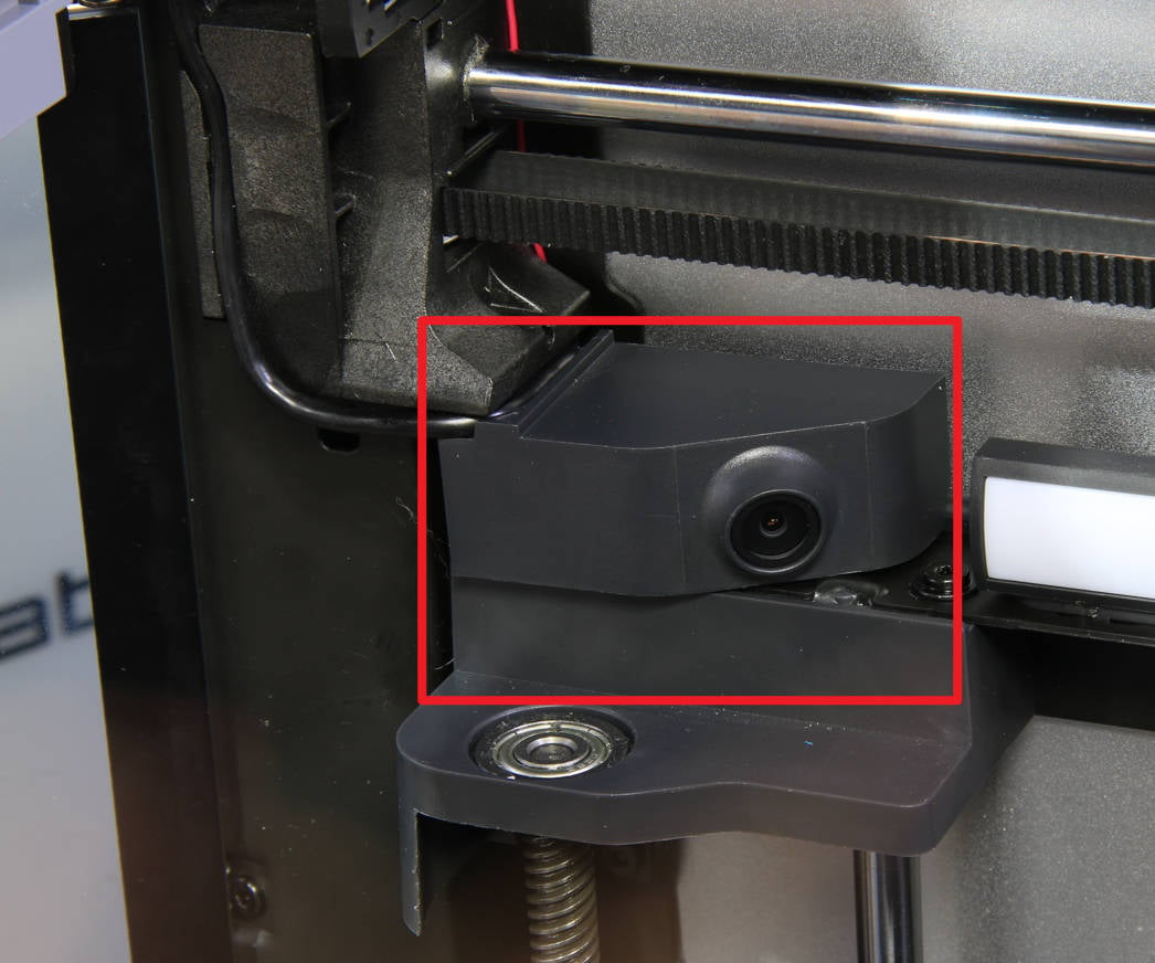
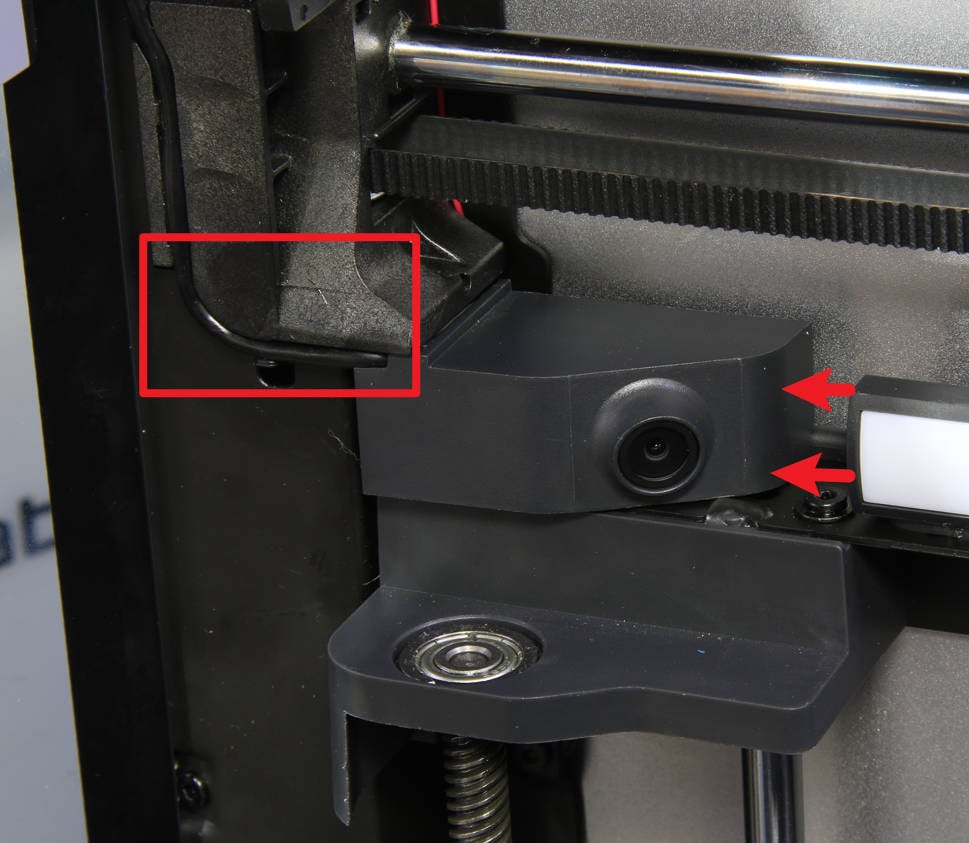
Place the camera in the position shown in the picture below, align the mounting holes, then push the camera in the direction of the arrow to install it in place, and finally, press the cable into the slot.
 |
 |
¶ Step 4 - Install the AP board
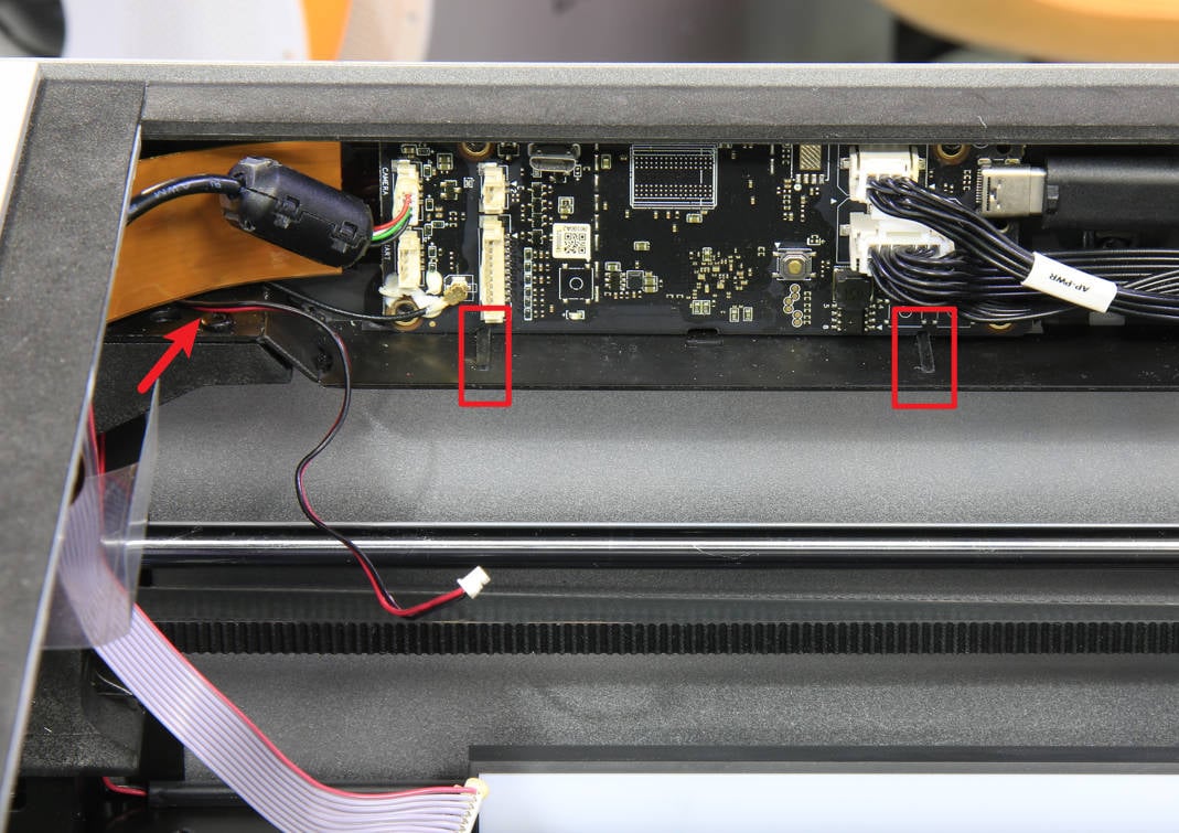
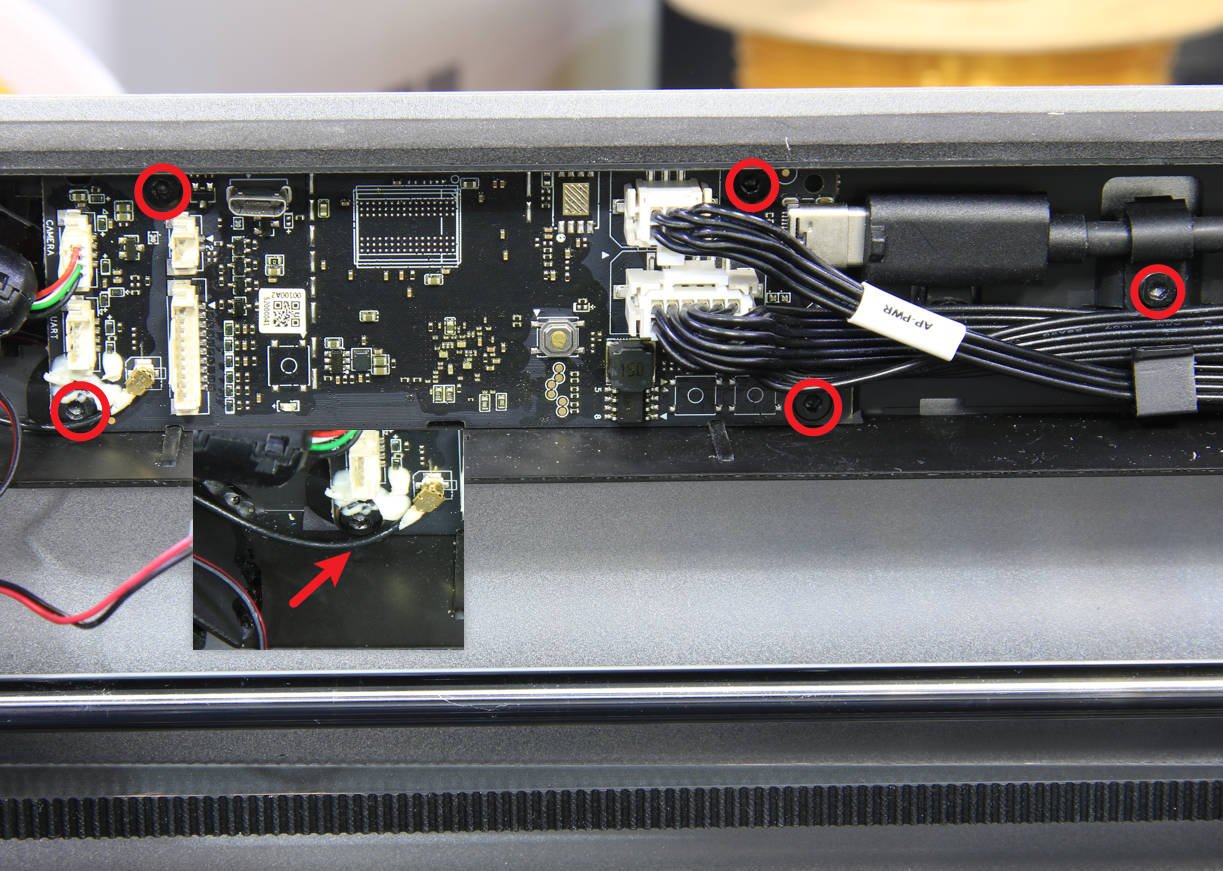
Install the AP board back to its original position according to the limited slots. Note that the LED light cable should be passed out under the FPC cable. Then, lock in 5 screws to fix the AP board and the USB cable clamping block. Check the connectors to confirm that they are normal.
 |
 |
¶ Step 5 - Connect the cables
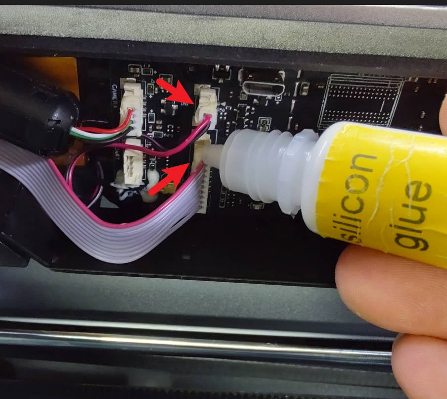
Connect the button board cable and the chamber LED cable to the corresponding connectors, it is recommended to use silicone glue to reinforce the connections.
 |
 |
¶ Step 6 - Close the AP cover
Press fit the AP cover back in place securely and finally place the glass top cover back on.
¶ How to verify completion/success
Connect the power cord and turn on the power.
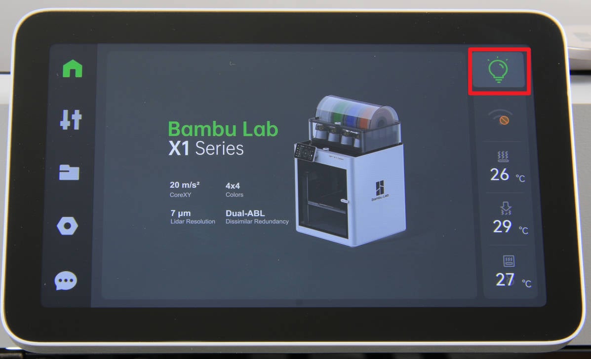
1. As shown in the picture below, click the light label to turn on and off the chamber LED to confirm that it works;
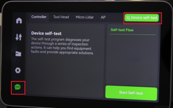
2. Run a Device self-test operation as shown below and if no errors occur, the replacement was successful.
Should you come across any issues, first retrace your steps and check all connections to try again. If problems persist, contact the service team for further assistance.
¶ Others
If you cannot confirm whether the cable is damaged or the LED lamp itself is burnt out, replace the cable together with the LED light. If it is clear that only the LED light itself is burned out, you can choose to replace only the LED light part.
¶ End Notes
We hope the detailed guide provided has been helpful and informative.
If this guide does not solve your problem, please submit a technical ticket, we will answer your questions and provide assistance.
If you have any suggestions or feedback on this Wiki, please leave a message in the comment area. Thank you for your support and attention!