¶ Heatbed Sensor Unit / Heatbed Piezo Interface Board
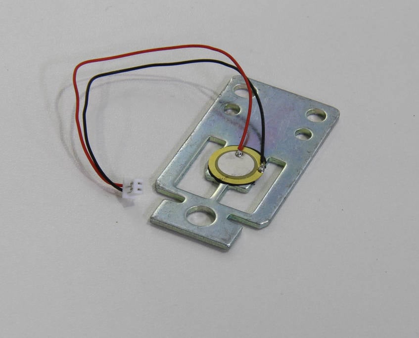
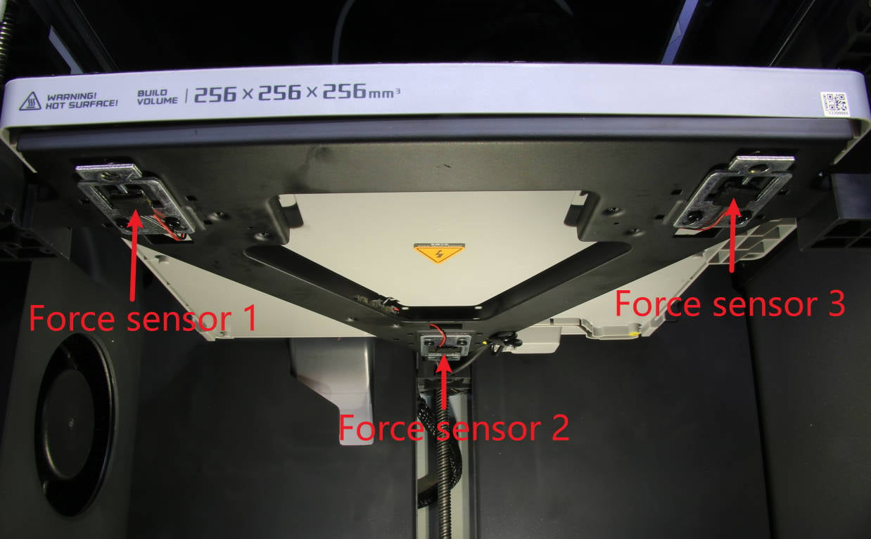
A sensor unit is a device capable of detecting force signals and converting them into usable output electrical signals according to specific rules. To monitor the surface pressure of the heat bed, 3 ceramic force sensors are installed on the underside of the heat bed.
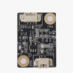
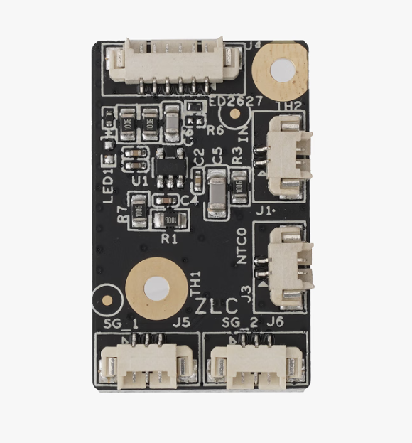
Pay attention to the difference between the heatbed piezo interface board and the heatbed sensor interface board:
Heatbed piezo interface board: There are 2 small circuit boards installed in the heatbed to connect heatbed sensor 1 and sensor 3.
Heatbed sensor interface board: The circuit board installed in the rear part of the heatbed with 5 connectors.
If the following three conditions are met simultaneously, or if there is obvious physical damage to the sensor, you need to replace the sensor:
1. You receive an error message stating, "The sensitivity of heat bed force sensor 1/2/3 is too low. The electronic connection to the sensor may be broken."
2. You have followed the HMS guide for troubleshooting but have not resolved the issue.
New sensor unit / New heatbed piezo interface board
H2.0 /H1.5 Allen key
¶ Safety warning and Machine state before starting operation
Please carefully follow the steps outlined in this guide to perform the replacement. Ensure the machine is powered OFF before starting any disassembly and assembly procedures.
We will use sensor 1 and the heatbed piezo interface board as examples in this replacement guide, but the process for replacing the other 2 sensors and the other heatbed piezo interface board is similar.
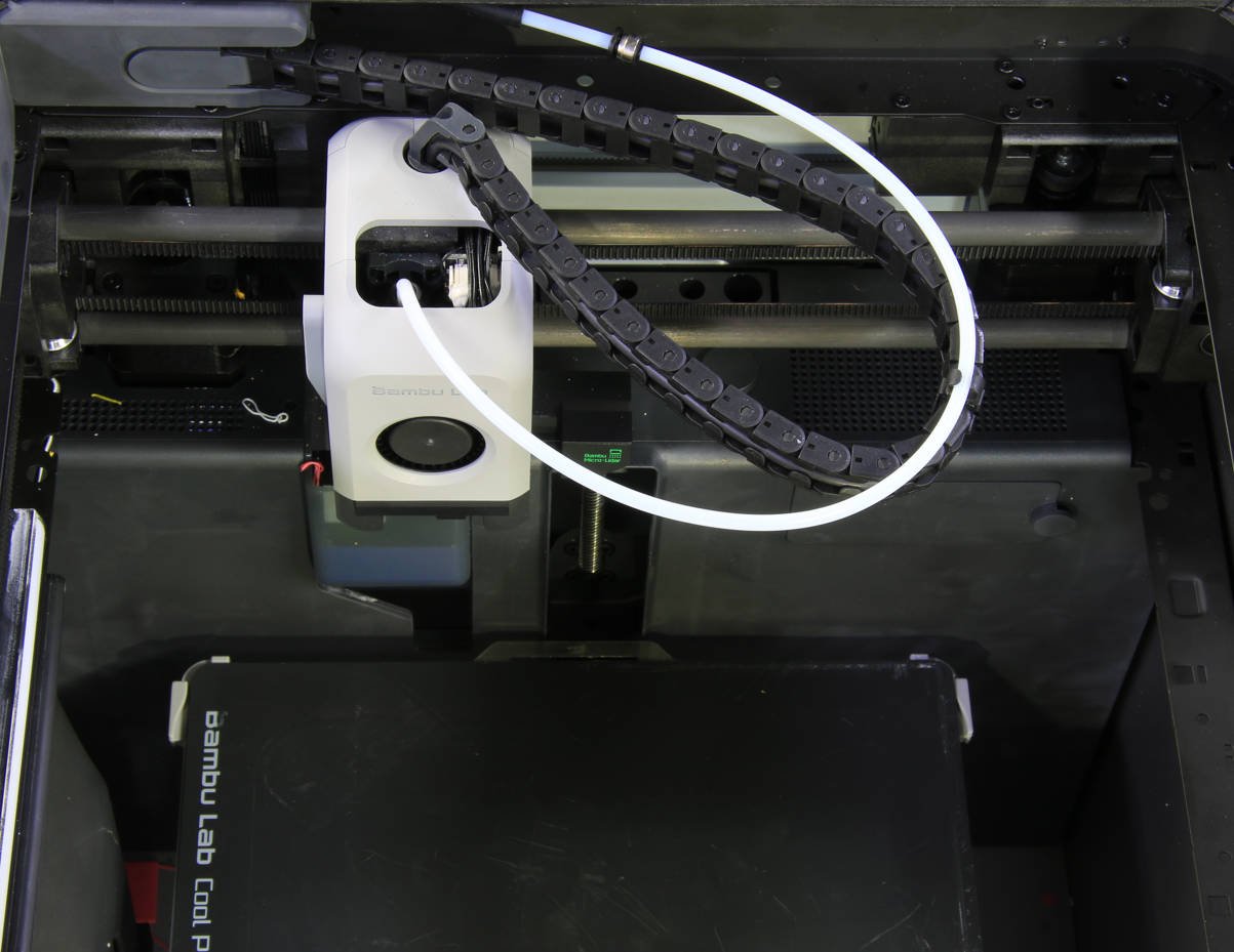
Power ON the printer and navigate to the movement menu on the LCD screen. Adjust the Z position of the heat bed to the middle. Once done, power OFF the printer, remove the top glass cover plate, and then move the toolhead to the excess chute.
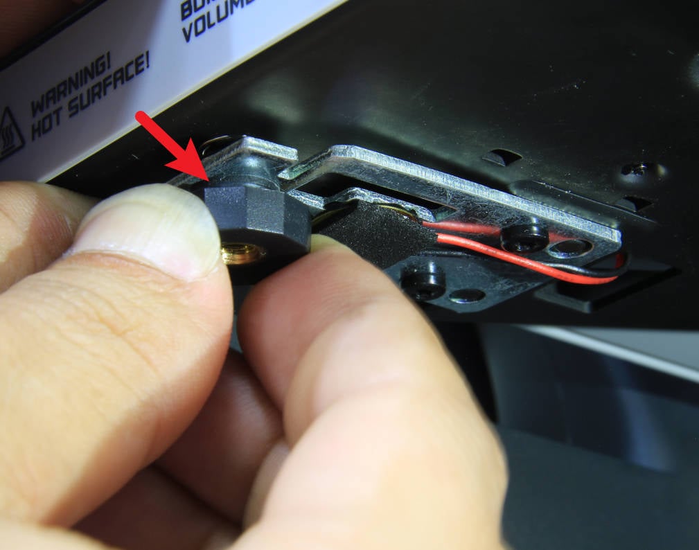
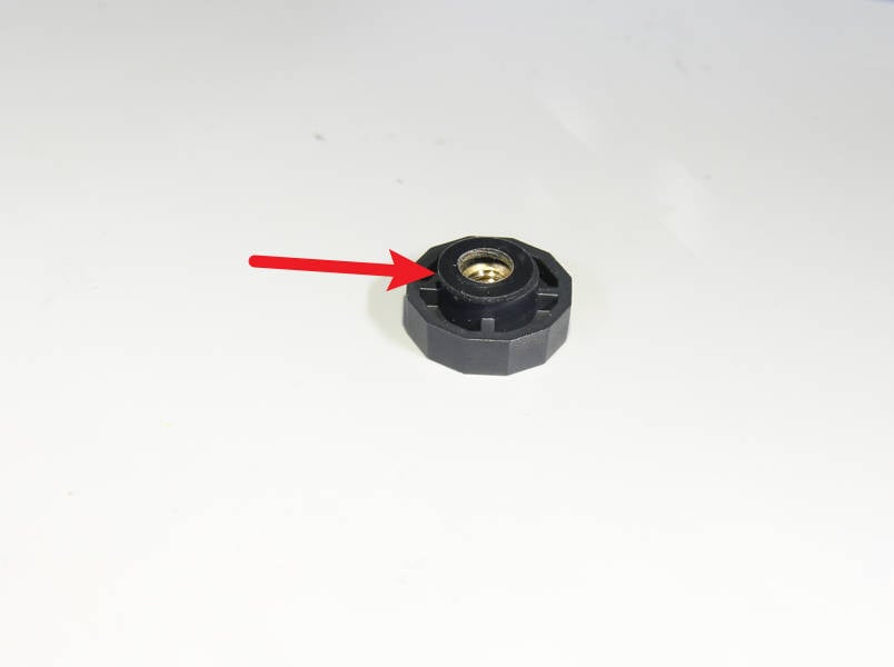
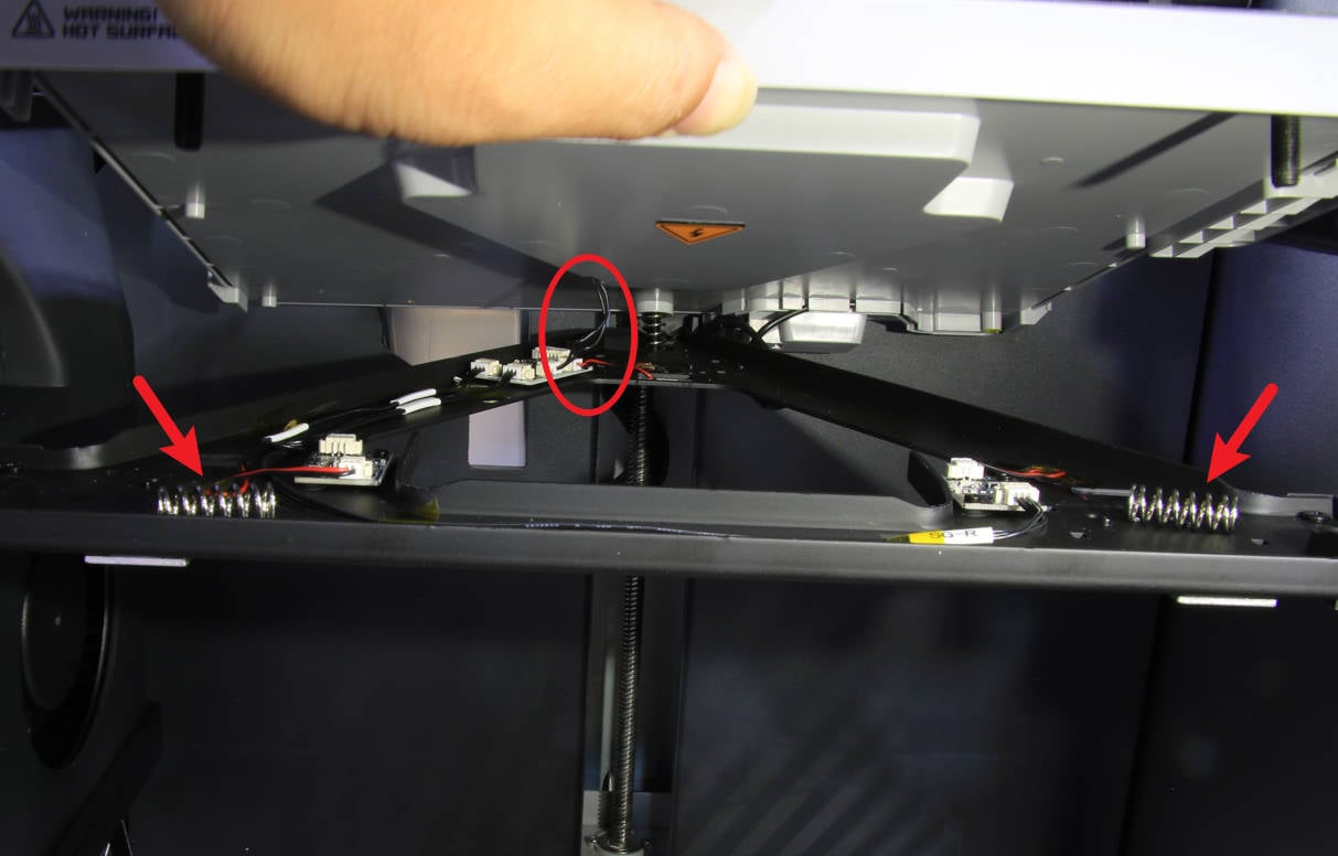
Unscrew the 3 pretension nuts to release the heat bed from the metal bracket. Note that each nut also has a rubber ring on top.
¶Step 4 - Open and temporarily prop up the heat bed
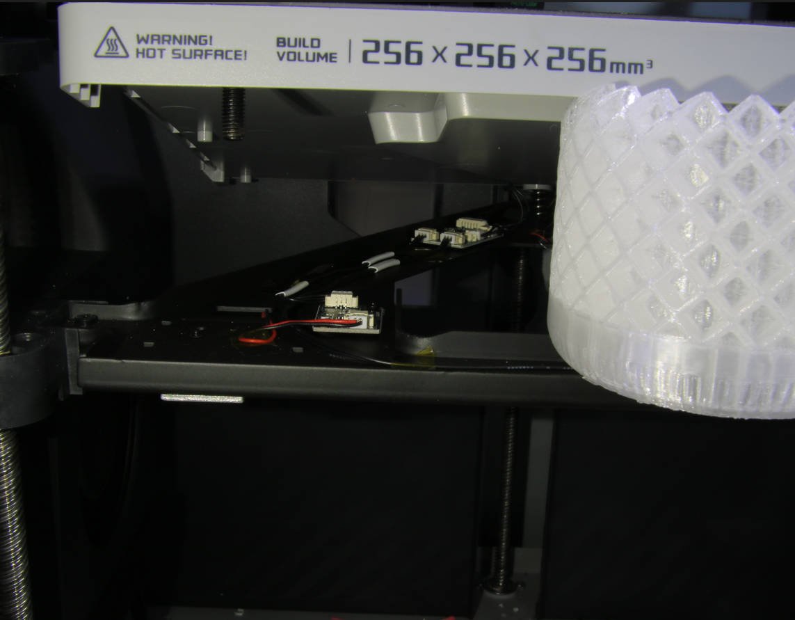
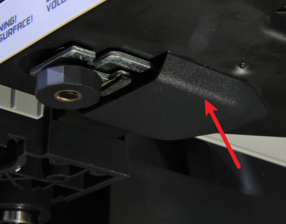
Open the heat bed carefully due to the cable inside and remove the loose pretension springs. To proceed with the procedure, temporarily support the heat bed. You can use a block to support the upper part of the heat bed (see picture below).
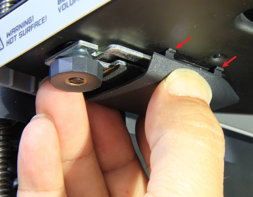
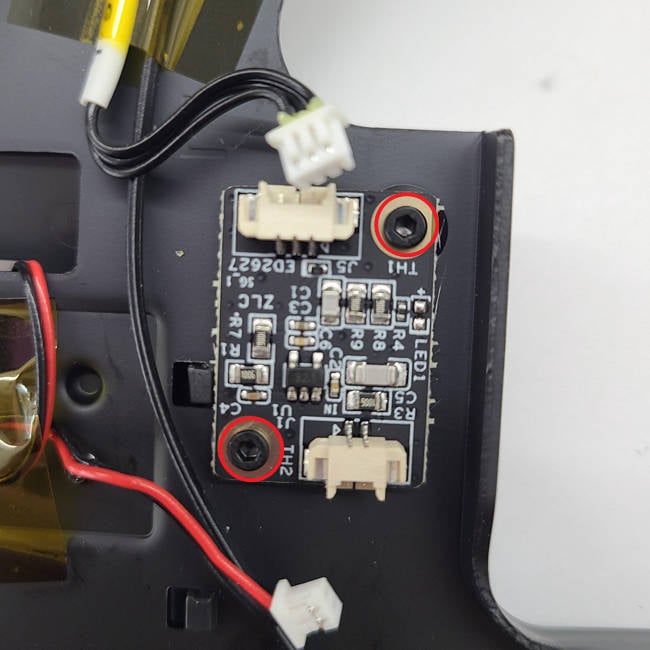
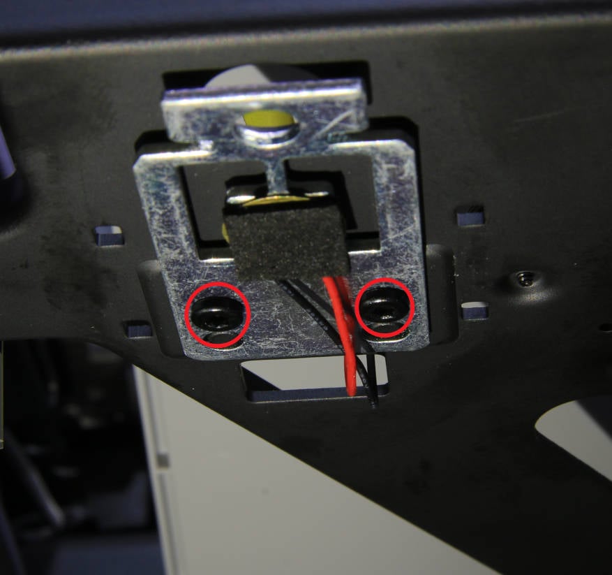
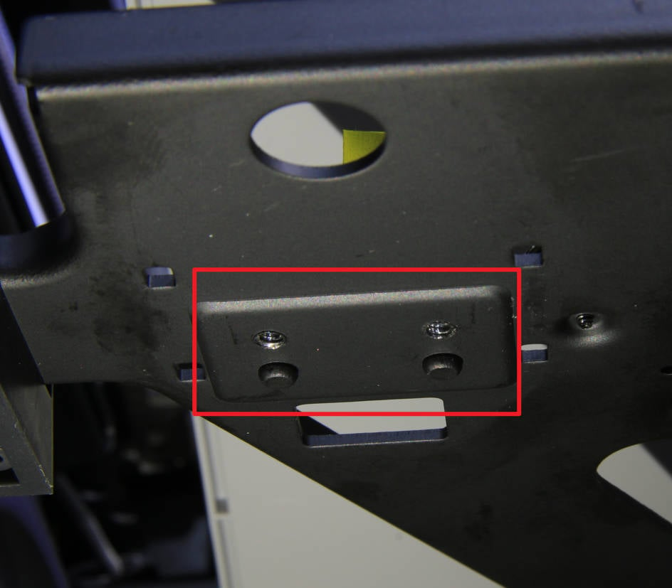
Prepare the new sensor for installation. Note that there are 2 limit posts to help ease the installation (see picture below). Secure the sensor in place by tightening the 2 screws.
¶ Step 5 Install the heatbed piezo interface board
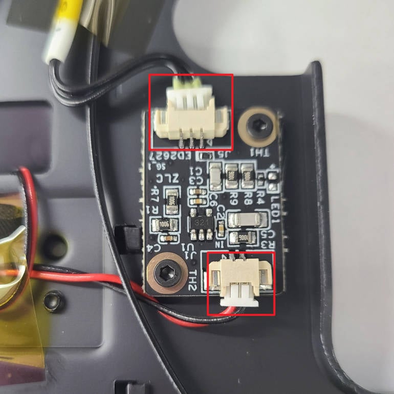
Install the heatbed piezo interface board on the bracket, lock in the 2 screws, and connect the 2 cables.
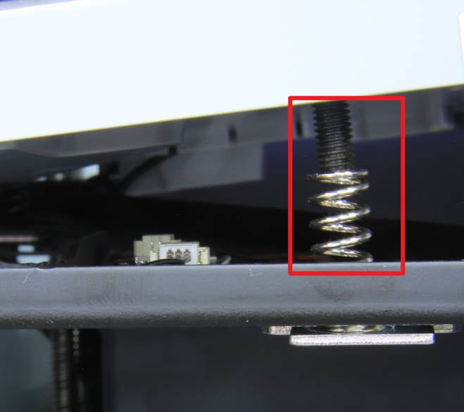
Hold the upper part of the heat bed and remove the support block you just used. Install the pretension springs to the heat bed screws one after another. In general, you only need to install the front two springs, because the rear one will not fall off.
Hold the upper part of the heat bed and remove the support block. Proceed to install the pretension springs onto the heat bed screws one by one. Typically, you only need to install the front two springs, as the rear one should remain in place.
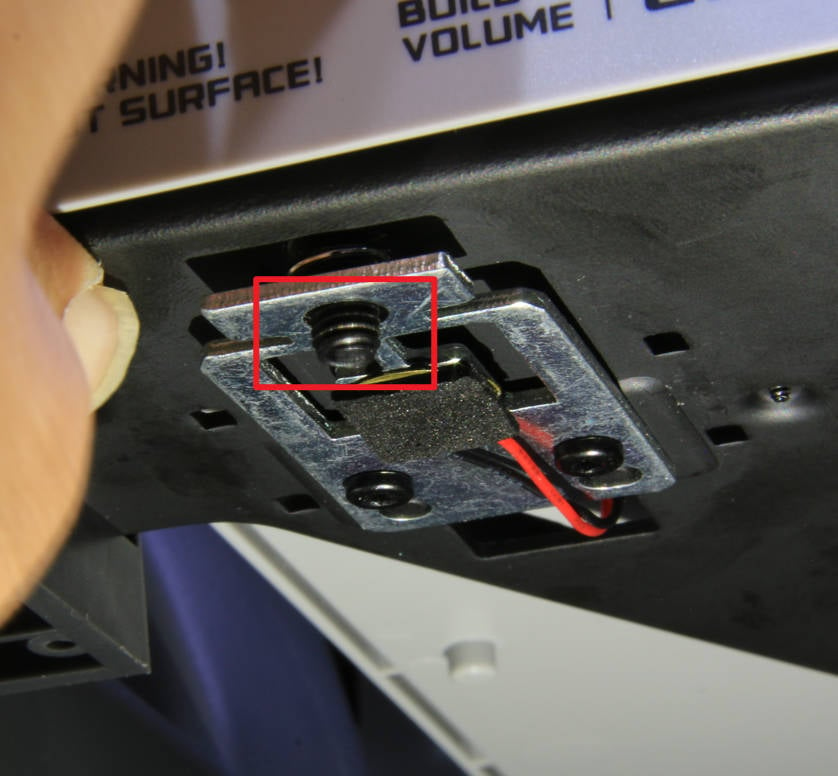
Now you can close the heat bed and mount them together. Gently press from the top of the heat bed to ensure that all three stubs can pass through the holes on the sensor holder.
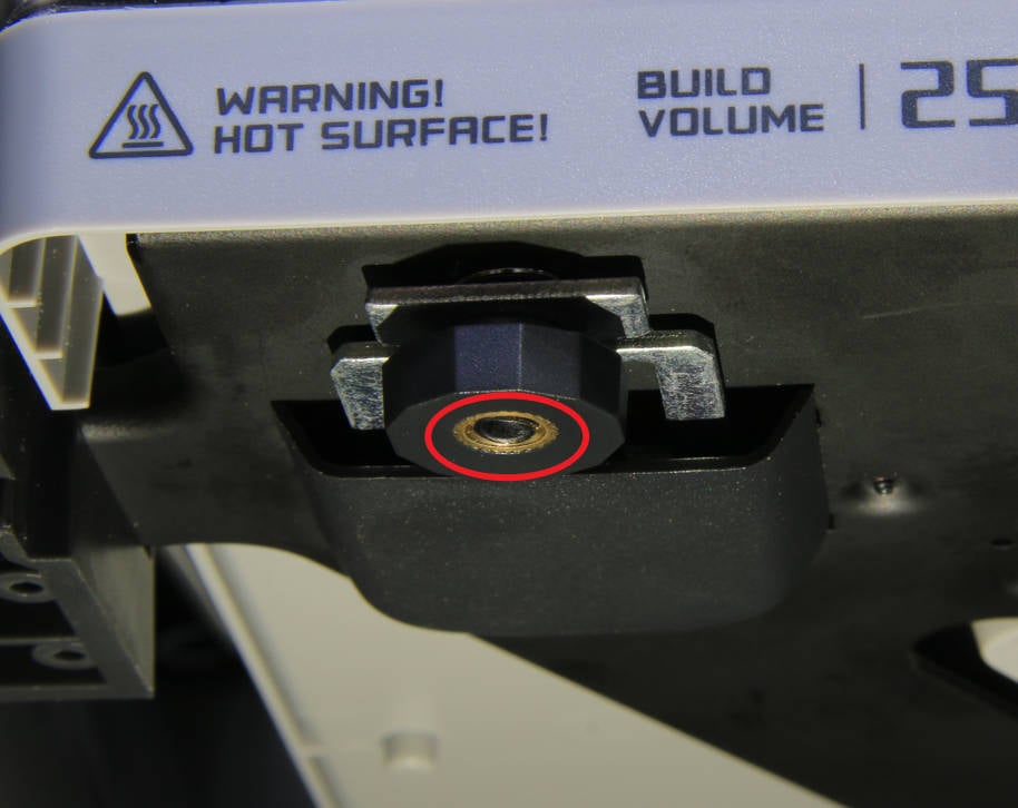
Place the rubber ring onto the 3 pretension nuts and then screw them in evenly, a little at a time. DO NOT lock them yet. Continue to screw in the nuts evenly, until the studs are flush with the bottom of the nuts (see picture below).
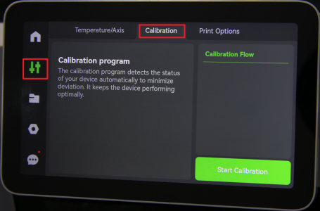
Ensure the chamber is clear of any prints or extrusions on the bed. Navigate to the settings menu on the LCD screen, select the Calibration tab, and press “Start Calibration.”
If everything proceeded as expected, and no errors or warnings occurred during the calibration, the replacement was successful. Otherwise, double-check the connections and retry. If issues persist, please contact the service team for further assistance.