It's crucial to power off the printer before performing any maintenance work on the printer and its electronics, including tool head wires, because leaving the printer on while conducting such tasks can cause a short circuit, which can lead to additional electronic damage and safety hazards.
When you perform maintenane or troubleshooting on the printer, you may be required to disassemble some parts, including the hotend. This process can expose wires and electrical components that could potentially short circuit if they come into contact with each other or with other metal or electronic components while the printer is still on. This can damage the electronics of the printer and cause further damage.
Therefore, it's essential to switch off the printer and disconnect it from the power source before doing any maintenance work. This will prevent any short circuits or damage to the printer's electronics. By doing so, you can avoid potential damage to the printer's electronic components and ensure that the maintenance work is performed safely and effectively.
If you have any concerns or questions about following this guide, open a new ticket in our Support Page and we will do our best to respond promptly and provide you with the assistance you need.
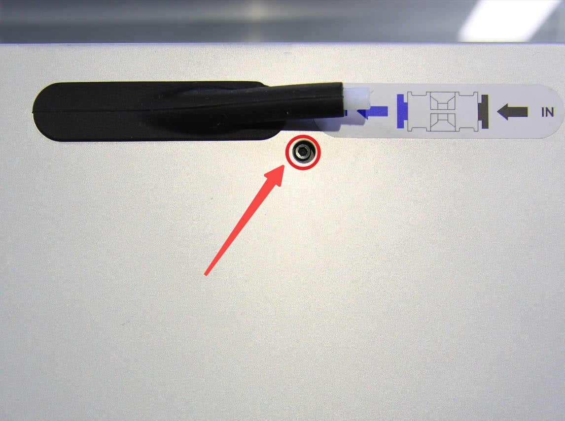
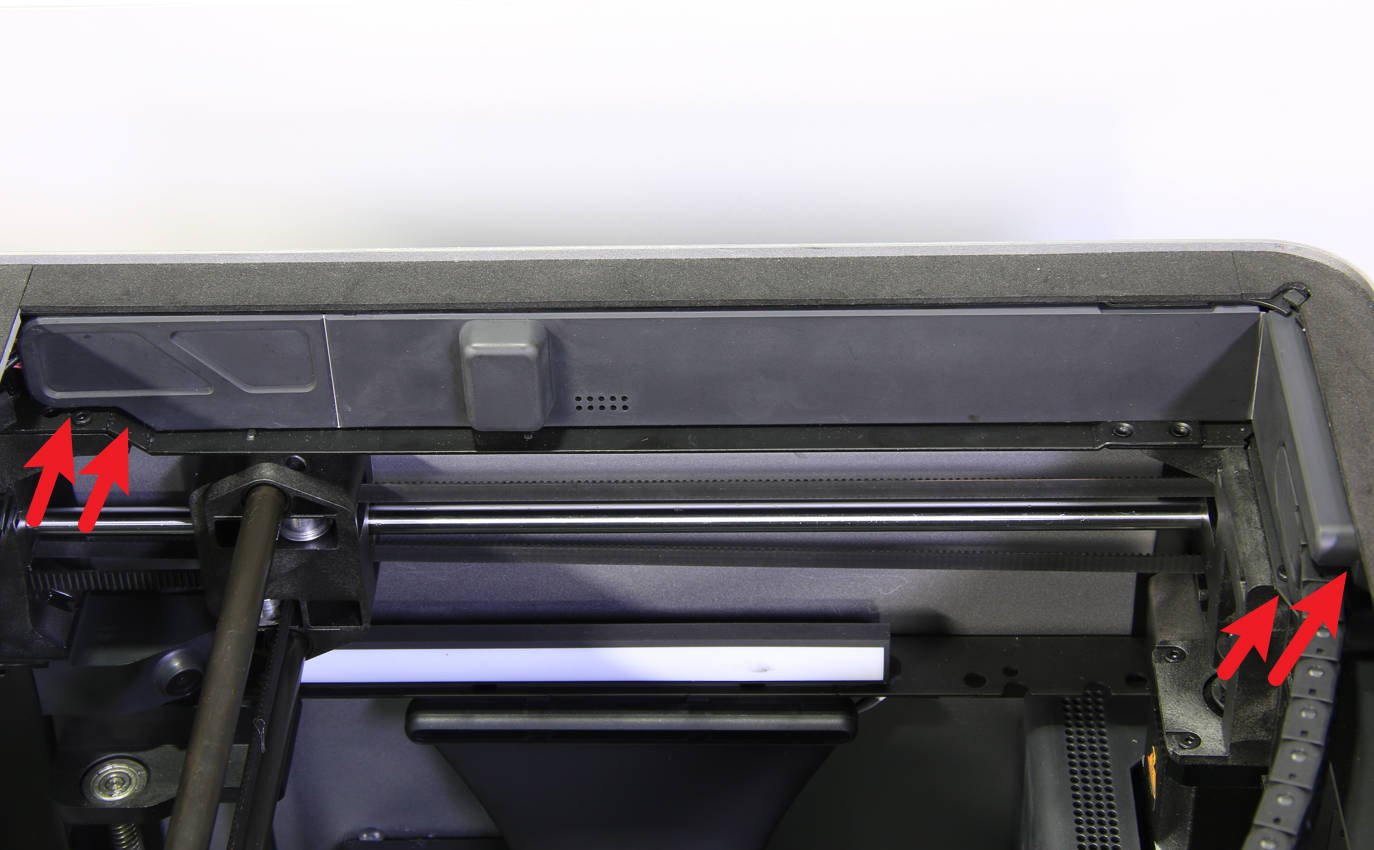
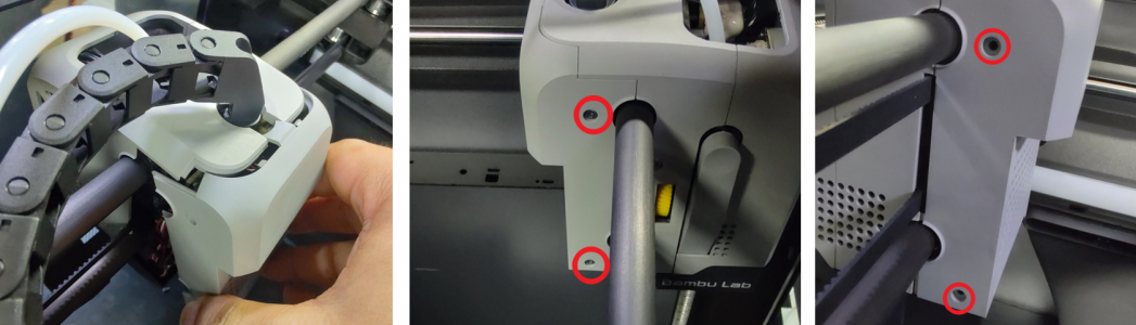
Remove 1 screw located under the PTFE bracket with an H1.5 hex key, open the AP main board cover from both ends, and then remove the AP main board cover from the beams.
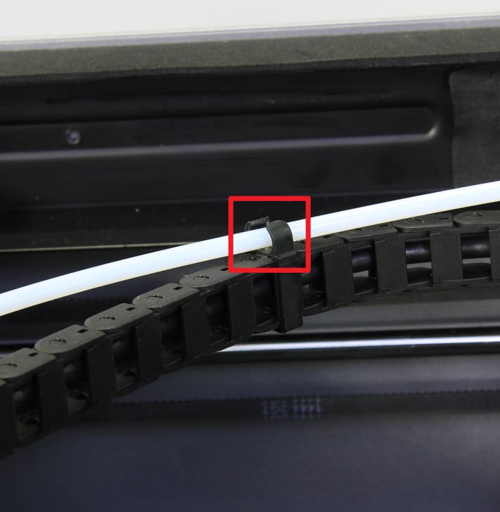
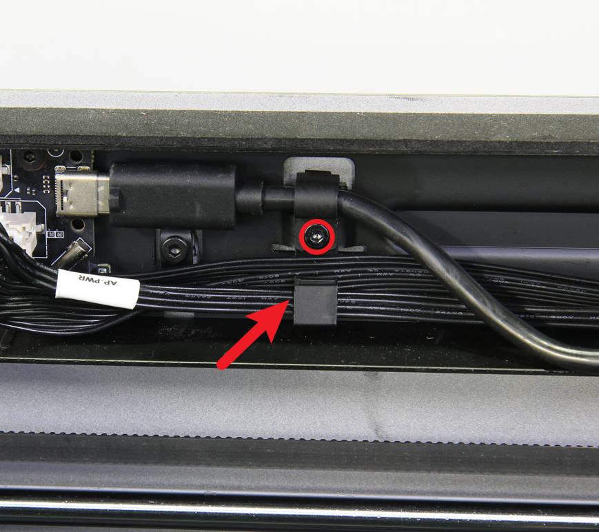
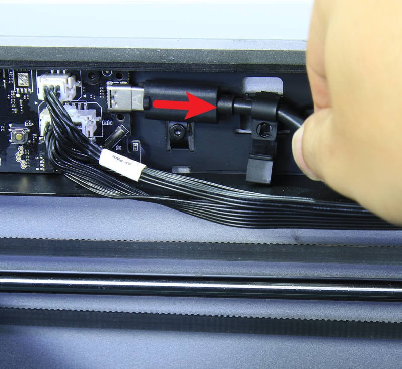
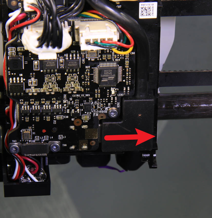
¶ Step 3 - Disconnect the USB connection (AP board)
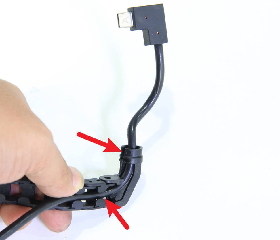
Remove the cable from the USB cable fixed block, remove 1 screw with the H2.0 hex key, and disconnect the USB cable from the AP board.
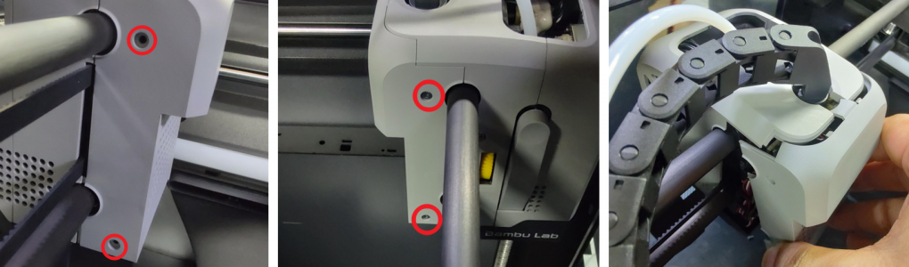
Undo the 4 screws securing the back cover of the tool head using the Allen key and remove the back cover.
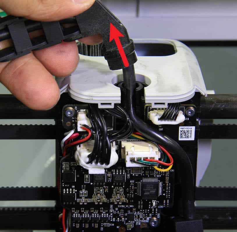
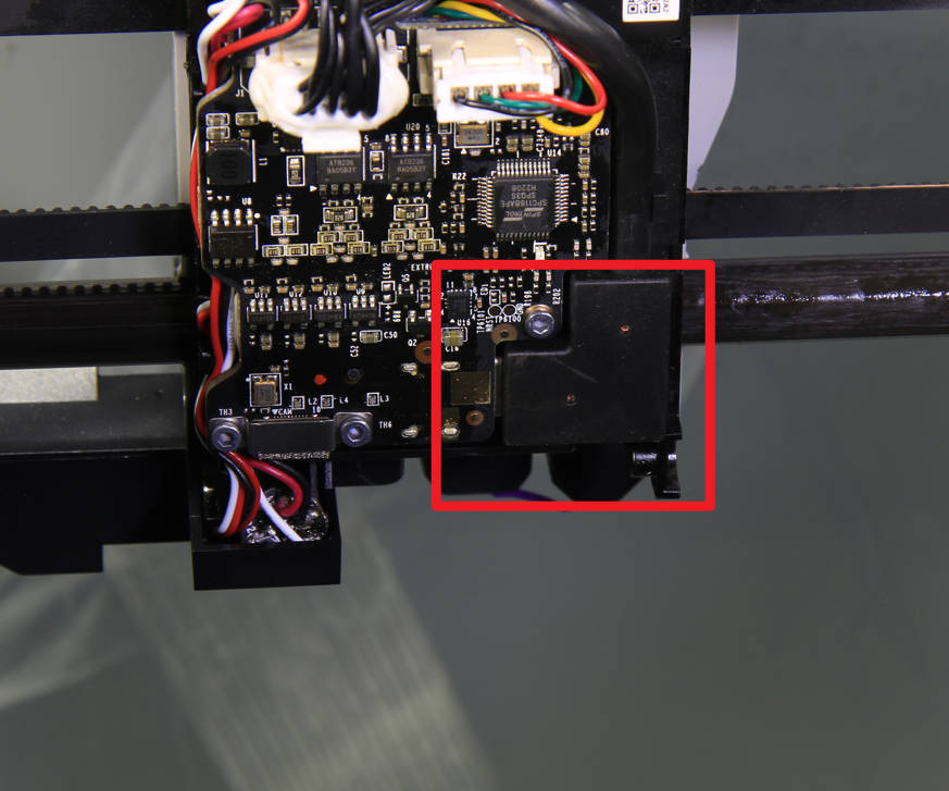
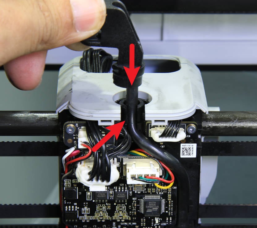
¶ Step 5 - Disconnect the USB connection (TH board)
Disconnect the USB cable from the extruder board, adjust the orientation of the USB cable holder as shown in the picture, and then pull up to remove the USB cable together with the holder from the tool head.
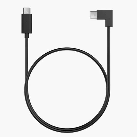
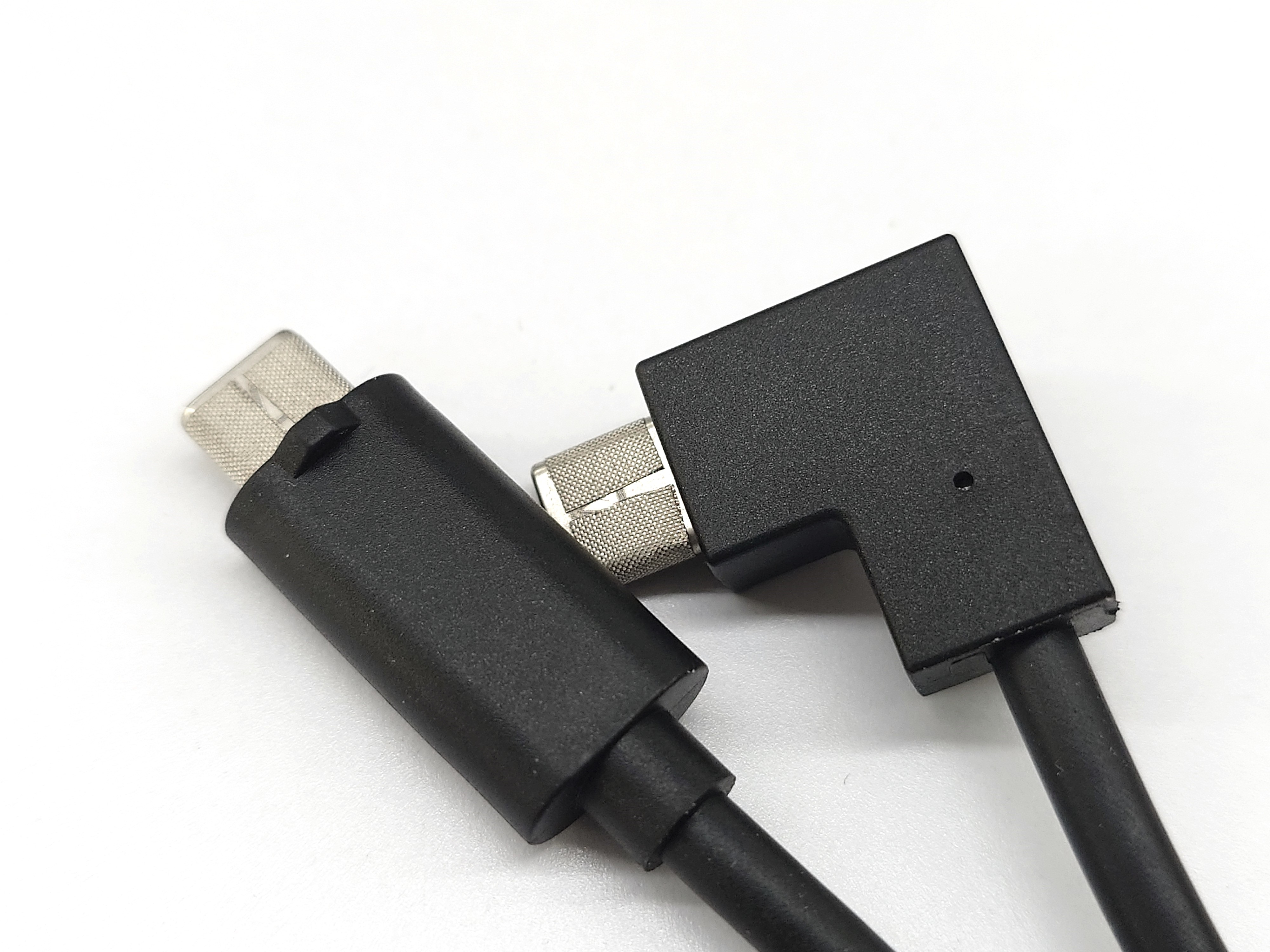
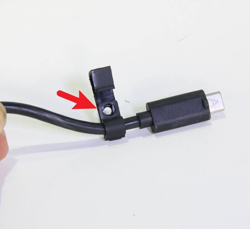
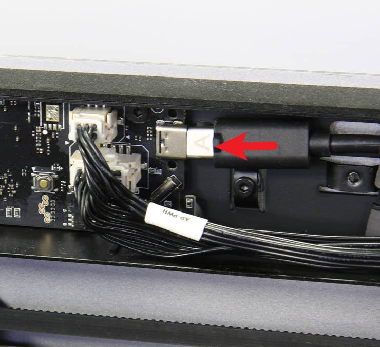
Connect the USB cable to the AP main board, pay attention to the letter A facing outward, lock the fixed block with 1 screw, and clamp the cables to the block.
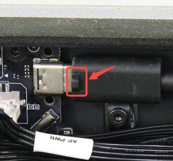
Note: In the new version, a piece of conductive fabric is glued here, so the letter A cannot be seen. The USB cable can be inserted with the protrusion facing outwards.
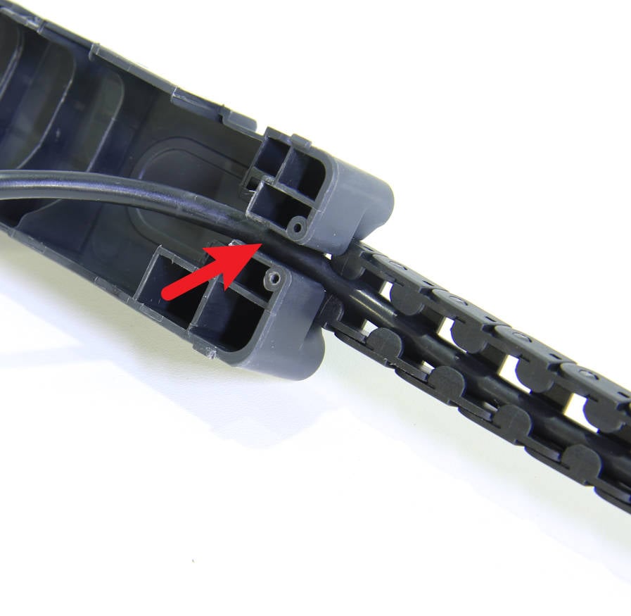
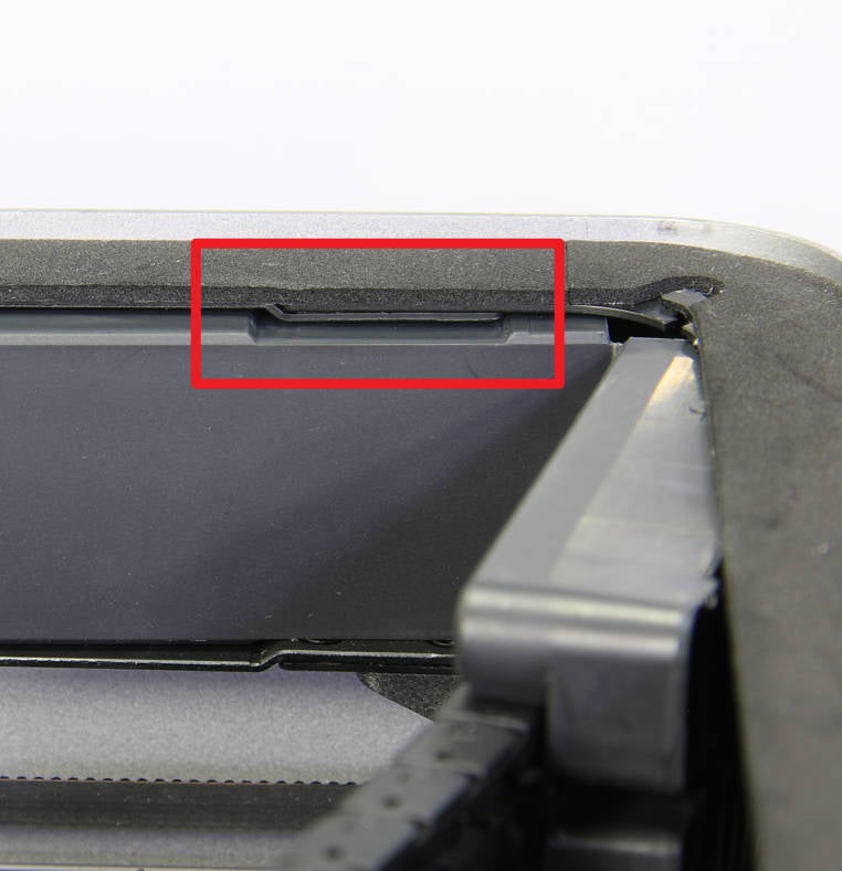
First align the gap shown in the figure below to install the AP main board cover, then install the AP main board cover in place, and lock a screw on the back of the printer to secure it.
1. Power ON the printer, and make sure the chamber is clear of any prints or extrusions on the bed.
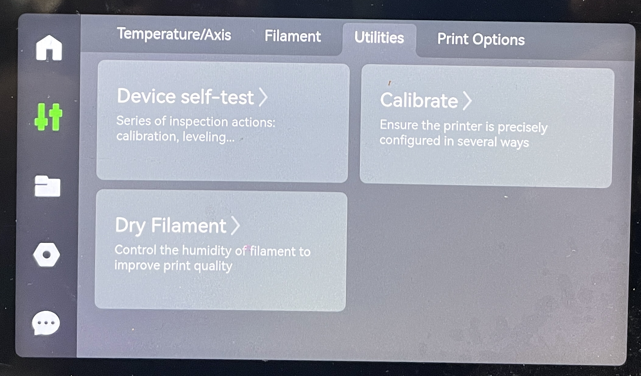
2. Navigate to the 'Utilities' menu displayed on the screen, then select "Calibrate>". Once the calibration process is complete, choose the "Device self-test".
If everything went according to plan, and no errors or warnings occurred during the calibration and self-test, the replacement was completed. Otherwise, check the connections and retry again.
If any issues persist, please contact the service team for further assistance.