¶ X1E Enclosure
The X1E uses almost the same enclosure as the X1C, and the disassembly and assembly methods of related accessories are basically the same.
This article will provide relevant guidelines for the disassembly and assembly of the X1E enclosure and explain the relevant precautions. You can also refer to this article for the disassembly and assembly of replaceable accessories involved in this disassembly process.
¶ Parts List
Associated Parts List
| NO. | Descriptions | Pics | NO. | Descriptions | Pics |
| 1 | Glass Cover Plate |
 |
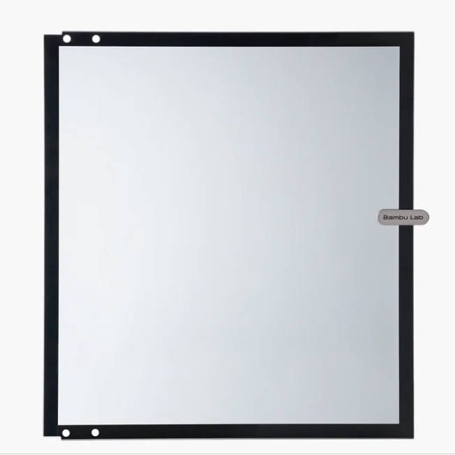
2 | Glass Front Door |
 |
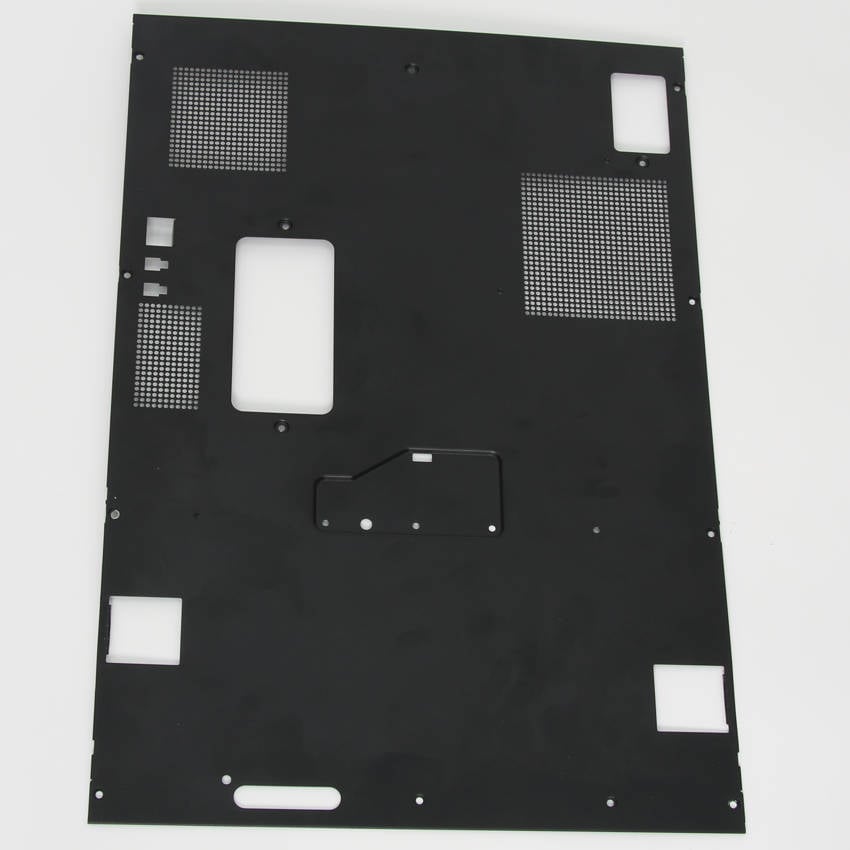
| 3 | X1E Metal Rear Panel |
 |
4 | X1E Right Panel |
 |
| 5 | X1E Left Panel |
 |
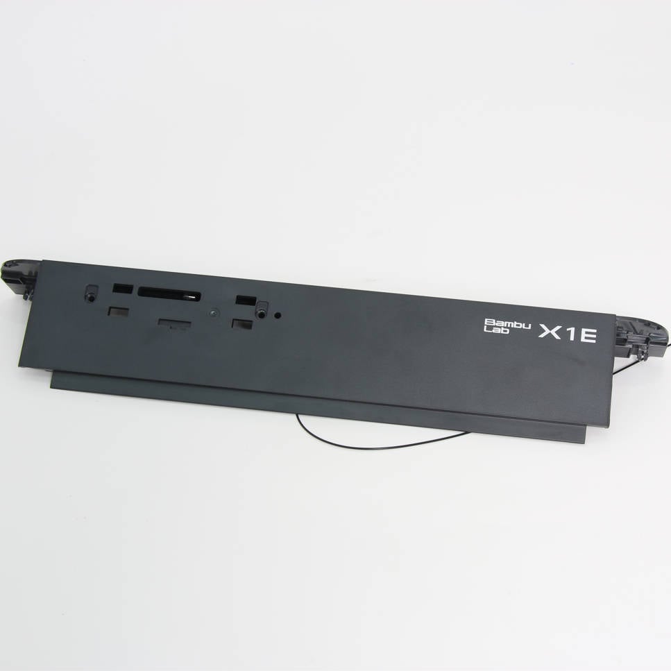
6 | X1E Front Cover |
 |
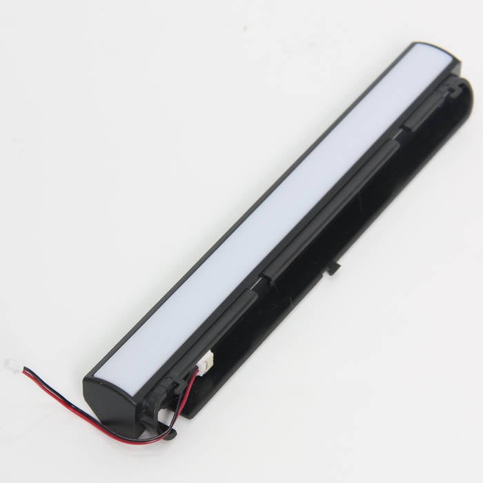
| 7 | Front LED |
 |
8 | Button Board |
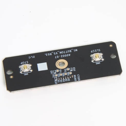 |
¶ Screws list
| Model | Position | Drawing | Model | Position | Drawing | ||
| Screw A | ST3*4.5 |
Rear panel (9PCS) |
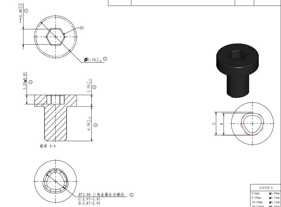 |
Screw B |
BT3*5
|
Rear panel、Air duct (4PCS/3PCS) |
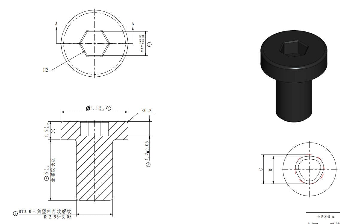 |
| Screw C | M3*4.5 |
Right panel, Rear panel, Left panel (1PCS,15PCS,15PCS) |
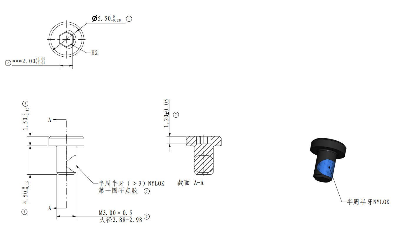
|
Screw D | M3*3 |
Glass front door (4CS) |
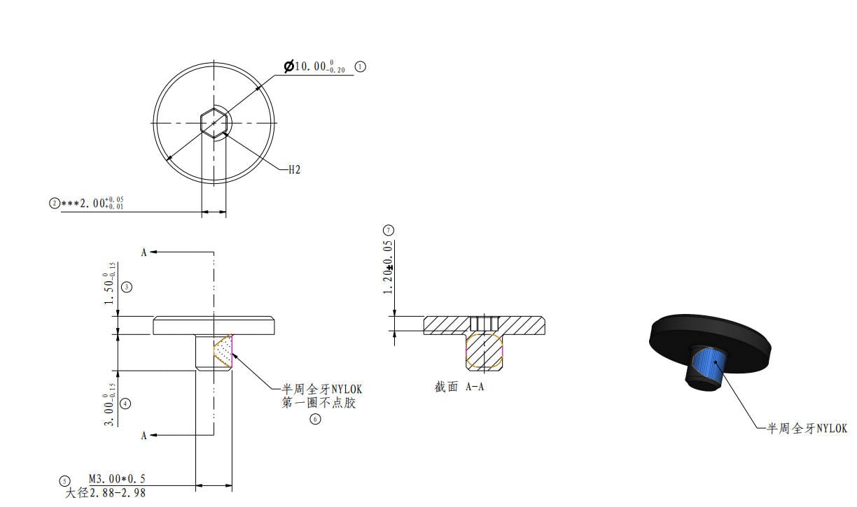 |
| Screw E | MG3*12 |
Aux. part cooling fan (3PCS) |
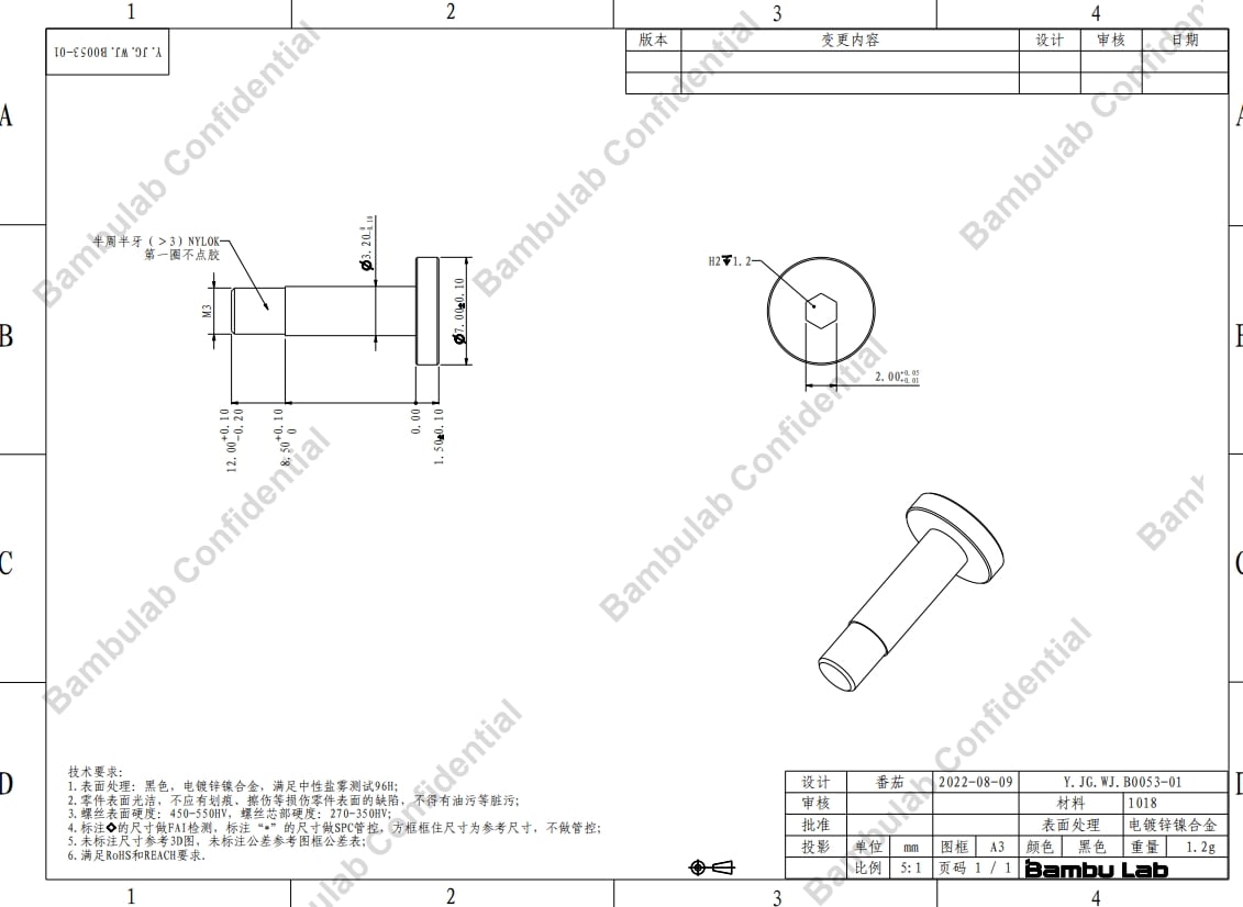
|
Screw F | M3*6 |
AP board、USB buckle (4PCS/1PCS/1PCS) |
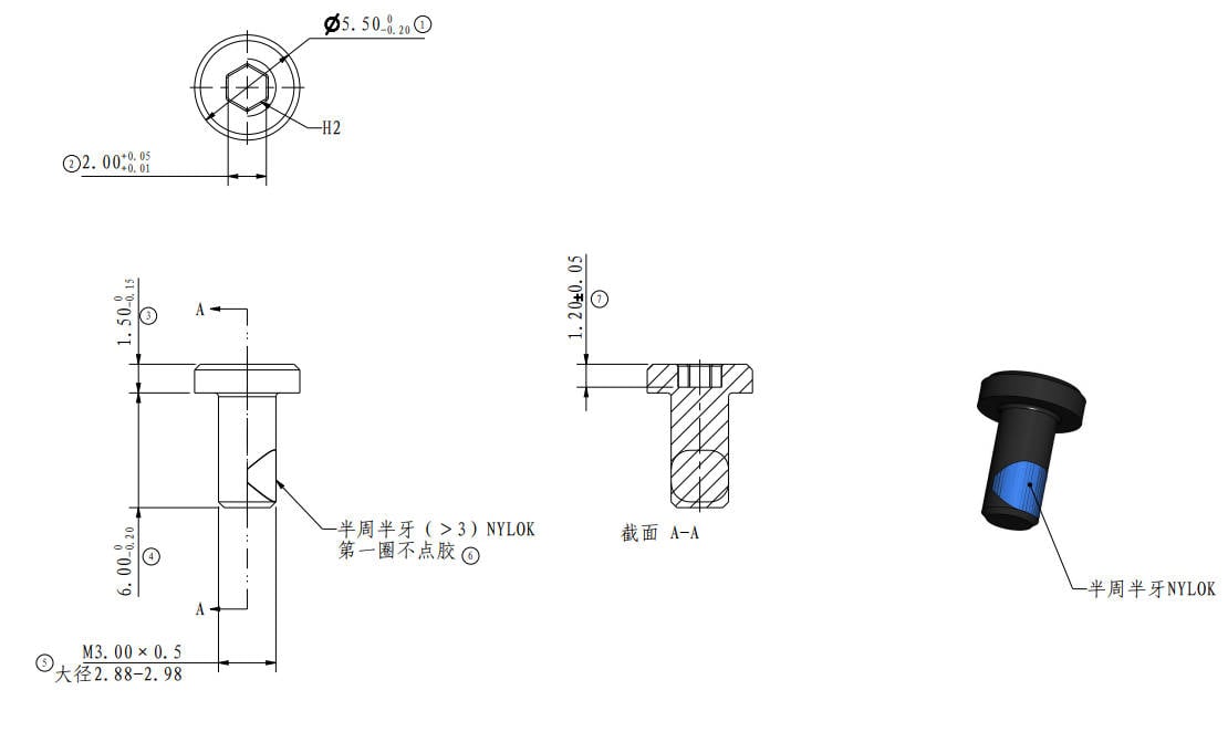
|
¶ Tools and materials needed
H1.5 /H2.0 hex key
¶ Safety Warning
IMPORTANT!
It's crucial to power off the printer before performing any maintenance work on the printer and its electronics, including tool head wires, because leaving the printer on while conducting such tasks can cause a short circuit, which can lead to additional electronic damage and safety hazards.
When you perform maintenane or troubleshooting on the printer, you may be required to disassemble some parts, including the hotend. This process can expose wires and electrical components that could potentially short circuit if they come into contact with each other or with other metal or electronic components while the printer is still on. This can damage the electronics of the printer and cause further damage.
Therefore, it's essential to switch off the printer and disconnect it from the power source before doing any maintenance work. This will prevent any short circuits or damage to the printer's electronics. By doing so, you can avoid potential damage to the printer's electronic components and ensure that the maintenance work is performed safely and effectively.
If you have any concerns or questions about following this guide, open a new ticket in our Support Page and we will do our best to respond promptly and provide you with the assistance you need.
¶ Disassembly
¶ Step 1: Remove the Rear Panel
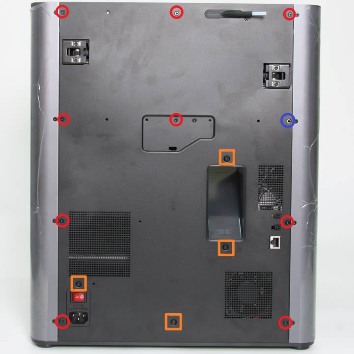
Remove the glass cover plate, and then as shown in Figure 1-1-1, remove 9 screws A, 4 screws B, and 1 screw C with the H2.0 hex key;
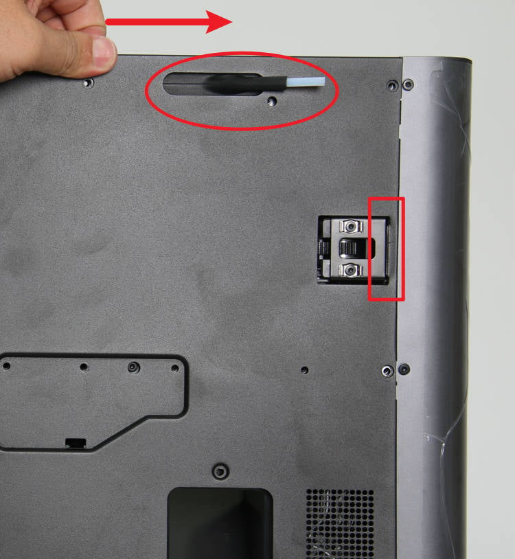
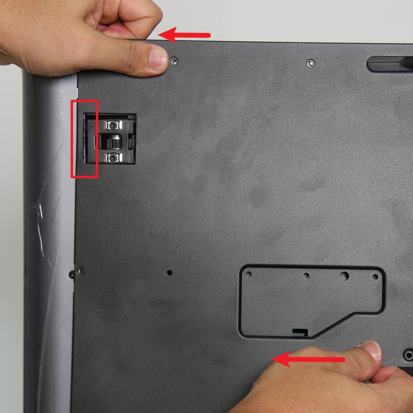
As shown in Figure 1-1-2, first push the rear panel to the right a little bit, and loosen the rear panel from the tensioner on the right side;
As shown in Figure 1-1-3, apply force to the left, release the rear panel from the left tensioner, and remove the rear panel.
|
|
|
¶ Step 2: Remove the Right Metal Panel
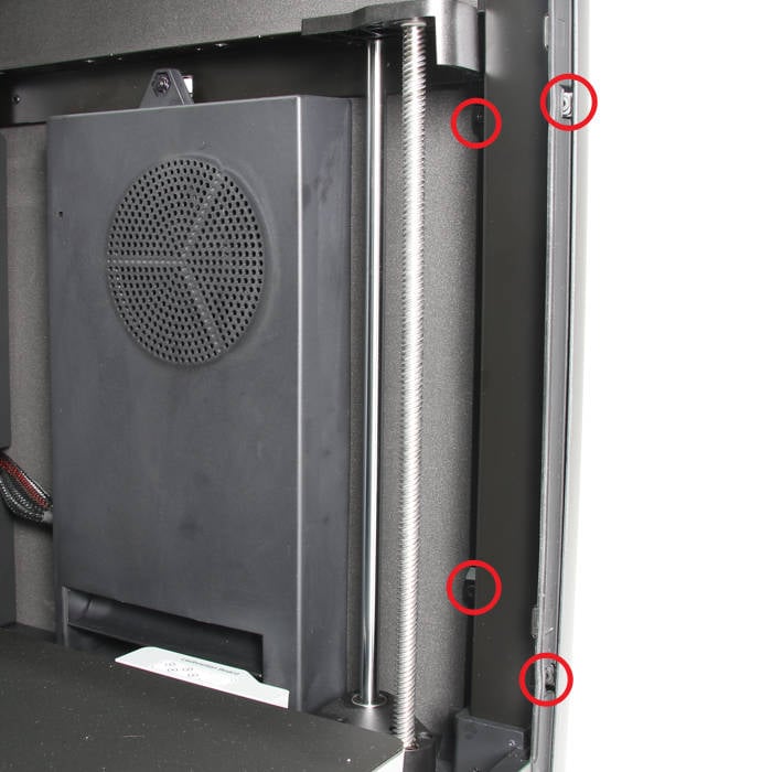
As shown in Figure 1-2-1, remove the 4 screws C behind the right metal panel with an H2.0 hex key ;
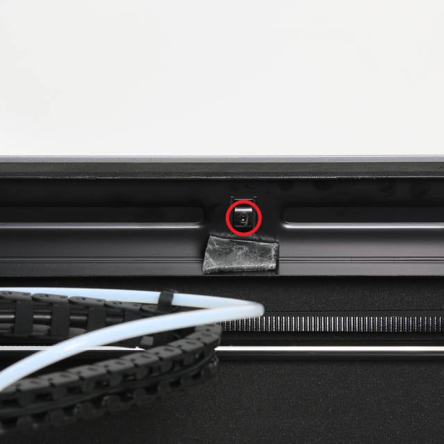
As shown in Figure 1-2-2, tear off the EVA pad and remove 1 screw C on the top of the right metal panel with an H2.0 hex key;
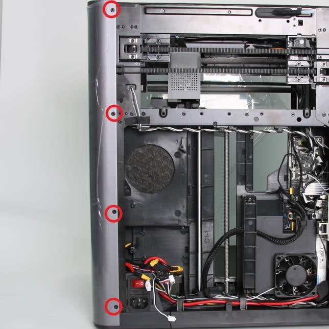
As shown in Figure 1-2-3, remove the 4 screws C on the right front column with an H2.0 hex key;
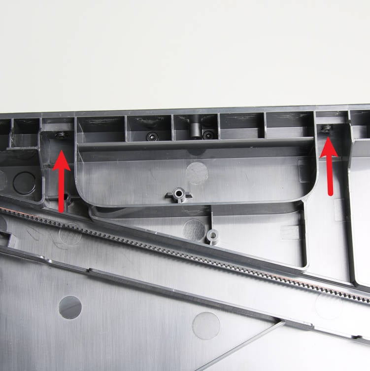
As shown in Figure 1-2-4, place the printer on its side with the right side panel facing up, and remove the 2 screws C at the bottom with an H2.0 hex key;
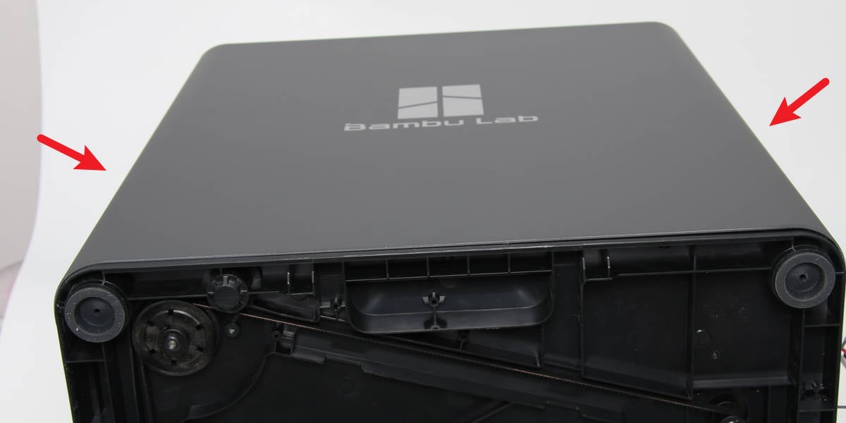
As shown in Figure 1-2-5, apply force on both sides of the right metal panel at the same time to remove it from the printer;
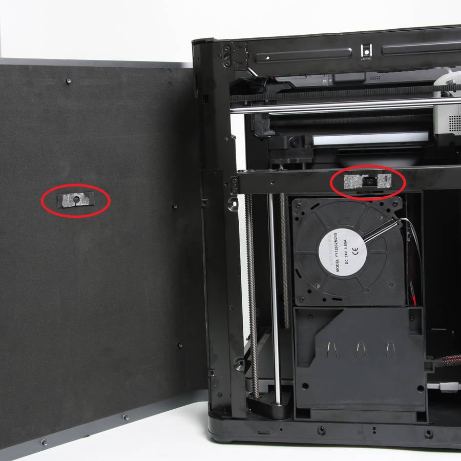
As shown in Figure 1-2-6, in addition to the screws, the right metal panel is foam-bonded to the printer at the middle beam, so it is not that easy to remove the right metal panel. It is recommended that at least two people work together.
|
|
|
|
|
|
¶ Step 3: Remove the Glass Front Door
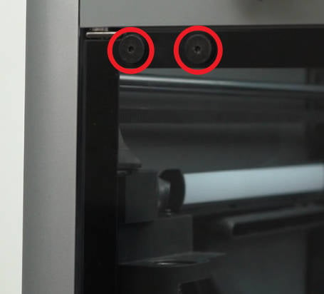
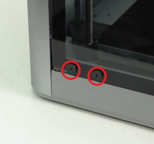
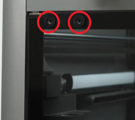
As shown in Figure 1-3-1 and Figure 1-3-2, remove 4 screws D with an H2.0 hex key ;
As shown in Figure 1-3-3, remove the four front door silicone pads with your hands, 2 PCS at the top and 2 PCS at the bottom. Be careful to hold the glass door with your hands to prevent it from falling, and then remove the glass front door.
|
|
|
¶ Step 4: Remove the Left Metal Panel
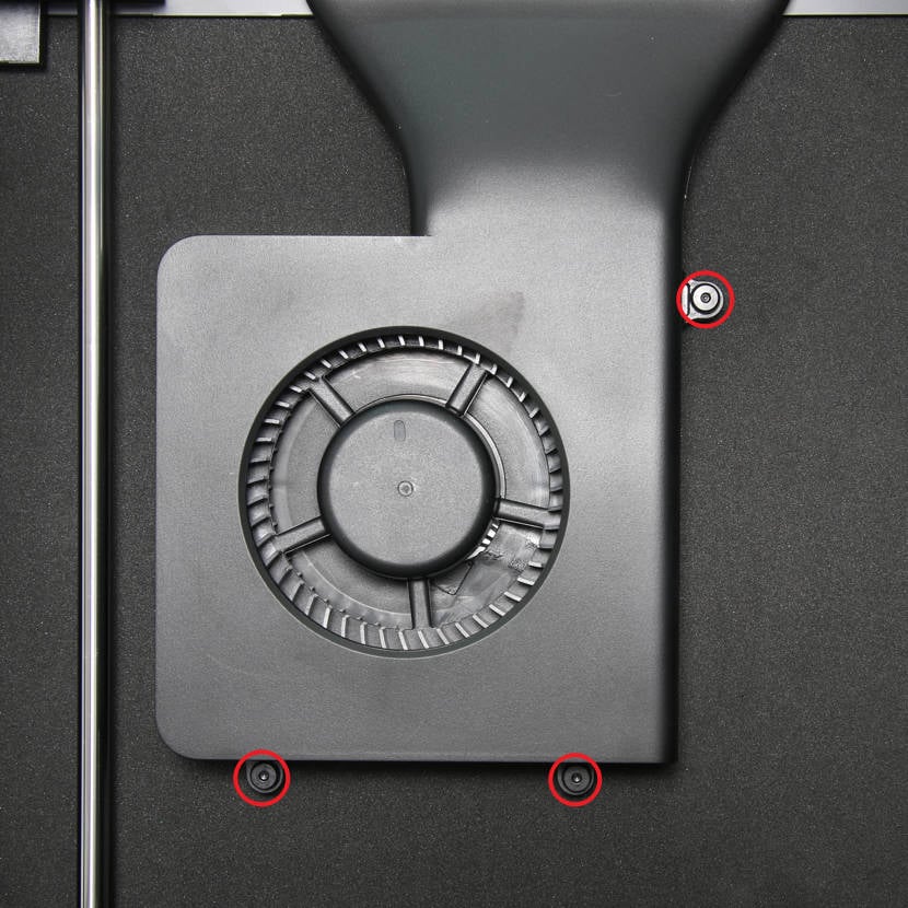
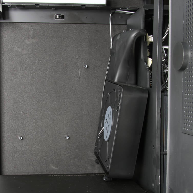
As shown in Fig. 1-4-1 and Fig. 1-4-2, remove 3 screws E with an H2.0 hex key, remove the aux part cooling fan, and place it on the bottom base;
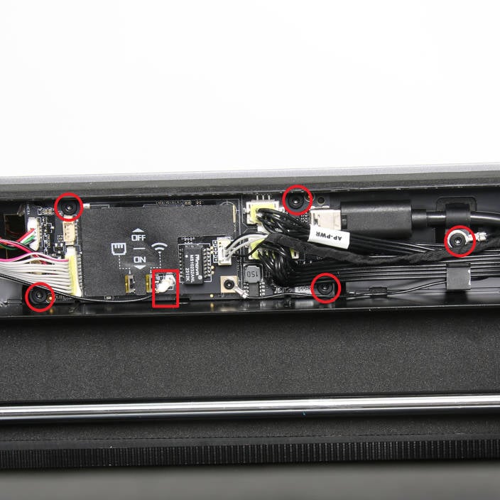
As shown in Fig. 1-4-3, open the AP board cover to show the screws and boards;
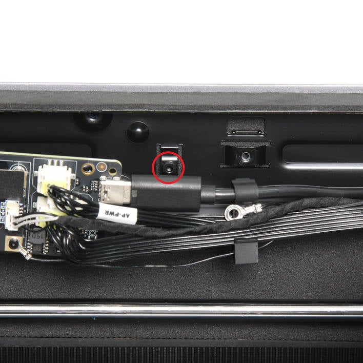
As shown in Fig. 1-4-4, disconnect the WIFI antenna, remove 5 screws F with an H2.0 hex key, and loosen the AP board and USB cable buckle from the top beam;
As shown in Fig. 1-4-5, remove 1 screw C on the top of the left metal panel with an H2.0 hex key;
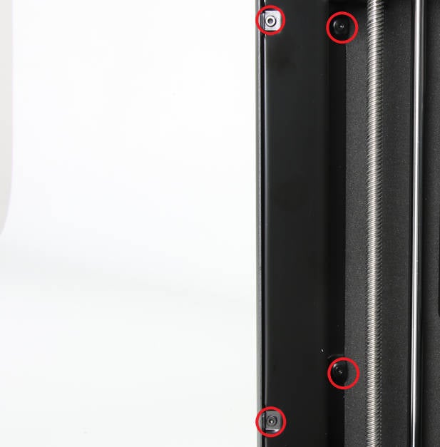
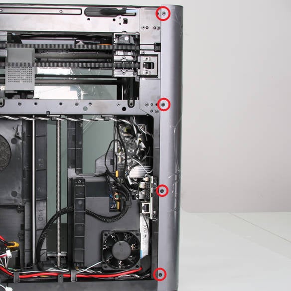
As shown in Fig. 1-4-6, remove the 4 screws C on the right front column with an H2.0 hex key;
As shown in Fig. 1-4-7, remove the 4 screws C behind the right metal panel with an H2.0 hex key ;
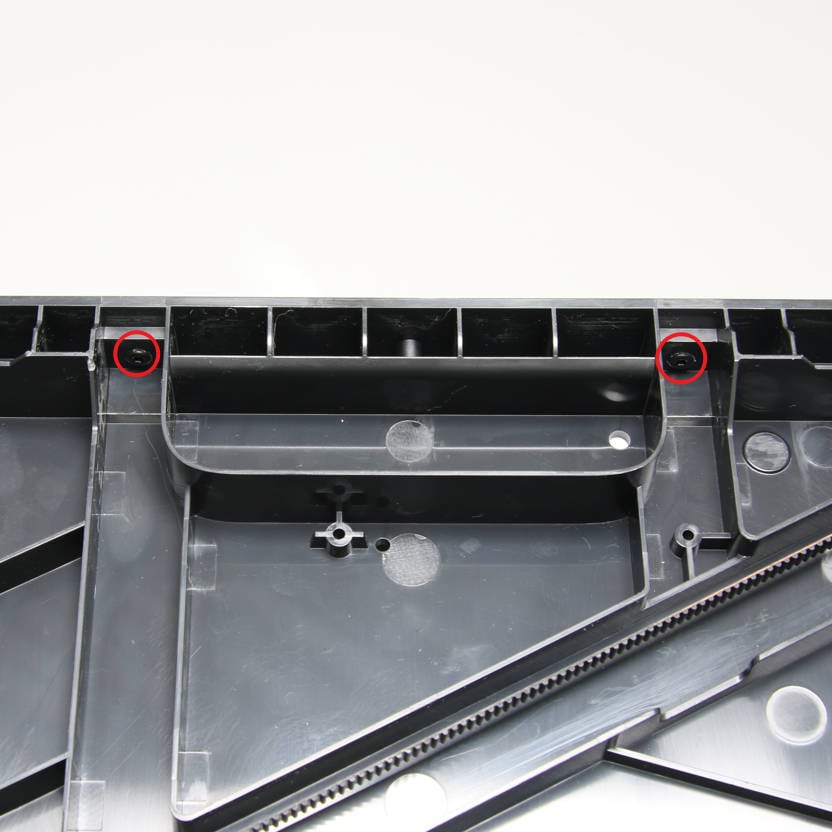
As shown in Fig. 1-4-8, place the printer on its side with the left side panel facing up, and remove the 2 screws C at the bottom with an H2.0 hex key;
As shown in Fig. 1-4-9, apply force on both sides of the right metal panel at the same time to remove it from the printer;
As shown in Figure 1-4-10, in addition to the screws, the left metal panel is foam-bonded to the printer at the middle beam, so it is not that easy to remove the left metal panel. It is recommended that at least two people work together.
|
|

|
|
|
|
|
|

|

|
¶ Step 5: Remove the front LED
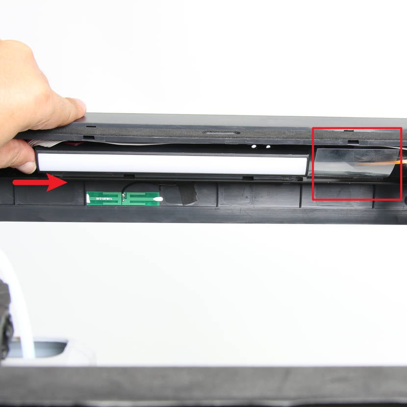
As shown in Fig. 1-5-1, uncover the screen flex cable limiting film, remove the fixing glue of the front LED light, and push the front LED hard in the direction of the arrow to unlock it;
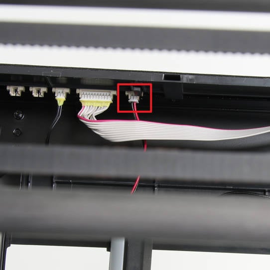
As shown in Fig. 1-5-2, disconnect the LED and remove the front LED light.
|
|
|
¶ Step 6: Remove the front cover
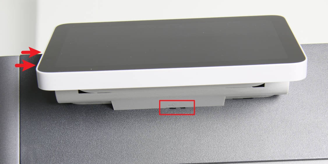
As shown in Fig. 1-6-1, press the screen lock and push the screen in the direction of the arrow to release the screen from the front cover;
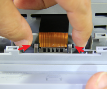
As shown in Fig. 1-6-2, press the locks on both sides of the connector to disconnect and remove the screen;
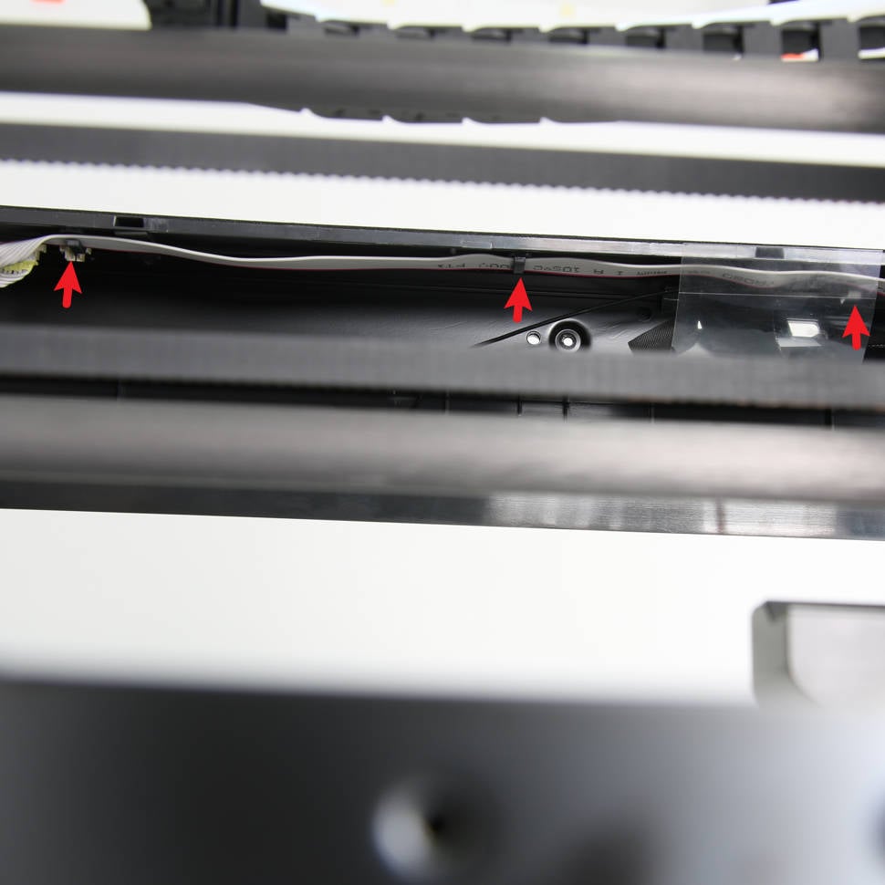
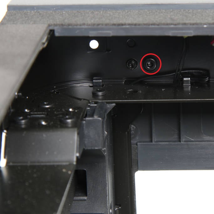
As shown in Fig. 1-6-3, loosen the WIFI antenna and button board cable from the cable clips;
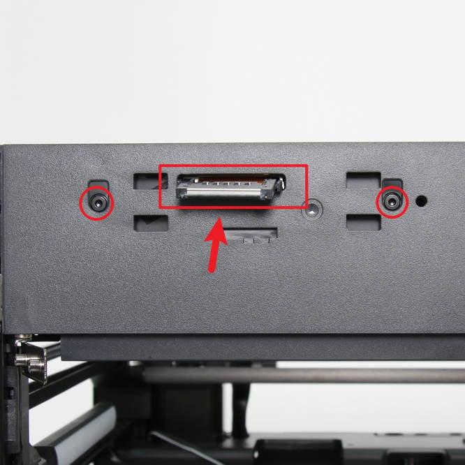
As shown in Fig. 1-6-4 and Fig. 1-6-5, use an H2.0 hex key to remove 2 screws A and 1 screw B, and push the screen cable back into the chamber;
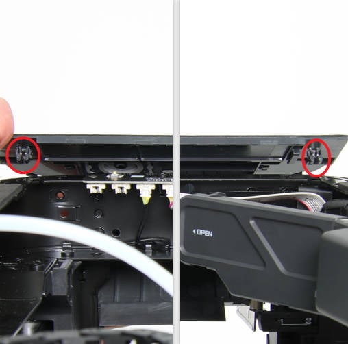
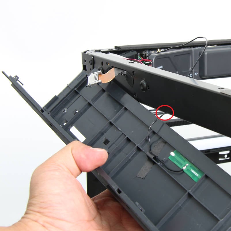
As shown in Fig. 1-6-6 and Fig. 1-6-7, press the buckles on the left and right ends of the front cover push upward to separate the front cover from the beam pull out the WIFI antenna, and remove the front cover.
|
|
|
|
|
|
|
|
|
¶ Step 7: Remove the Button Board
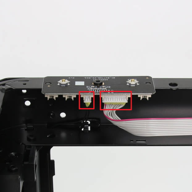
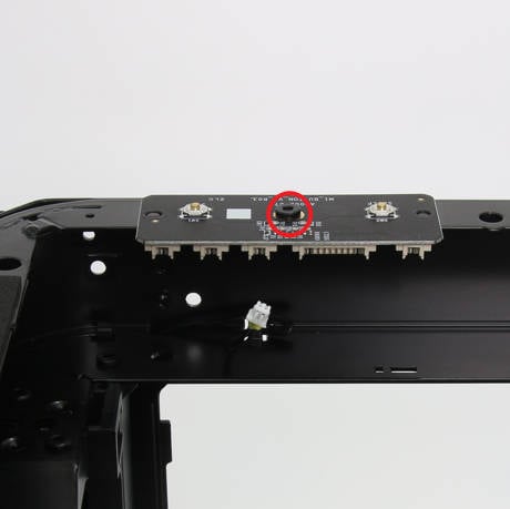
As shown in Fig.1-7-1, disconnect the front door detection switch cable and button board connection cable;
As shown in Fig. 1-7-2, use an H2.0 hex wrench to unscrew 1 screw F and remove the button board.
|
|
¶ Assembly
¶ Step 1: Install the Button Board
As shown in Fig. 2-1-1, install the button board to the front cross beam and lock in 1 screw F;
As shown in Fig. 2-1-2, connect the front door detection switch cable and button board connection cable.

|

|
¶ Step 2: Install the Front Cover
As shown in Fig. 2-2-1, pass the WIFI antenna through the cable hole on the front beam, and the screen cable through the square cable hole on the front cover;
As shown in Fig. 2-2-2, align the buckles at the left and right ends with the mounting holes on the rack, and install the front cover into place;
As shown in Fig. 2-2-3 and Fig. 2-2-4, lock in 2 screws A and 1 screw B;
As shown in Fig. 2-2-5, organize the button board cable and WIFI cable into the cable buckles;
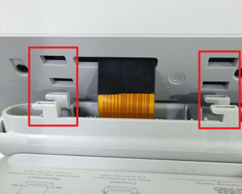
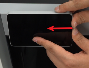
As shown in Fig. 2-2-6, Fig. 2-2-7, and Fig. 2-2-8, connect the screen and install the screen in place.

|

|

|

|

|

|
|
|
¶ Step 3: Install the front LED
As shown in Fig. 2-3-1, connect the front LED cable to the button board;
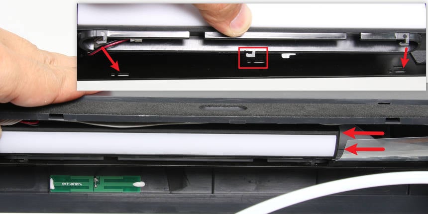
As shown in Fig. 2-3-2, align with the three mounting holes, install the front LED on the front beam, and then press the LED in the direction of the arrow to install the front LED in place.
|
 |
|
¶ Step 4: Install the Light Metal Panel
As shown in Fig. 2-4-1, install the left metal panel to the printer placed on its side and align the installation position;
As shown in Fig. 2-4-2, lock 2 screws C on the bottom;
As shown in Fig. 2-4-3, place the printer upright, align the screw holes, and lock 1 screw C on the top beam;
As shown in Fig. 2-4-4, lock 4 screws C on the left front pillar;
As shown in Fig. 2-4-5, lock 4 screws C on the rear of the left panel;
Note: When locking the screws on the left metal panel, the position may be deviated, making it difficult to lock in the screws. For the 8 screws on the left front column and the rear, you can leave them unfastened until all the screws are screwed in.
As shown in Fi. 2-4-6 and Fig. 2-4-7, install the AP board in place, then lock in 5 screws F, fix the AP board and USB cable buckle (including ground cable), and close the AP board cover ;
As shown in Fig. 2-4-8 and Fig. 2-4-9, install the auxiliary part cooling fan and lock in 3 screws E.

|

|

|

|

|

|

|

|

|
¶ Step 5: Install the Glass Front Door
As shown in Fig. 2-5-1, install the glass front door on the front door hinge, and place 4 front door silicone pads on the screw positions. Be careful to hold the glass door with your hands to prevent the door from falling;
As shown in Fig. 2-5-2 and Fig. 2-3-3, lock 2 screws D on both the upper and lower hinges of the front door.

|

|

|
¶ Step 6: Install the Right Metal Panel
As shown in Figure 2-6-1, install the right metal panel to the printer and align the installation position;
As shown in Figure 2-6-2, lock 2 screws C on the base;
As shown in Figure 2-6-3, place the printer upright, align the screw holes, lock 1 screw C on the top beam, and stick the EVA pad back to its original position;
As shown in Figure 2-6-4, lock 4 screws C in the right front column;
As shown in Figure 2-6-5, lock 4 screws C at the rear part of the right metal panel.
Note: When locking the screws on the right metal panel, the position may be deviated, making it difficult to lock in the screws. For the 8 screws on the right front column and the rear, you can leave them unfastened until all the screws are screwed in.

|

|

|

|

|
¶ Step 6: Install the Rear Panel
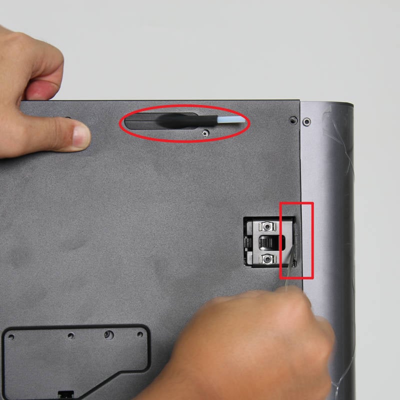
As shown in Figure 2-6-1, first pass the tube bracket through the rear panel, and then install the part near the tensioner on the right side in place, you can the hex key to press the edge to install it;
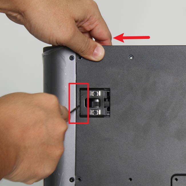
As shown in Figure 2-6-2, pull the rear panel to the left and install the part near the left tensioner in place, you can use the hex to press the edge to assist in the installation;
As shown in Figure 2-6-3, lock in 9 screws A, 4 screws B, and 1 screw C to fix the rear panel.
|
|

|
¶ Verify the functionality
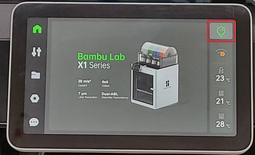
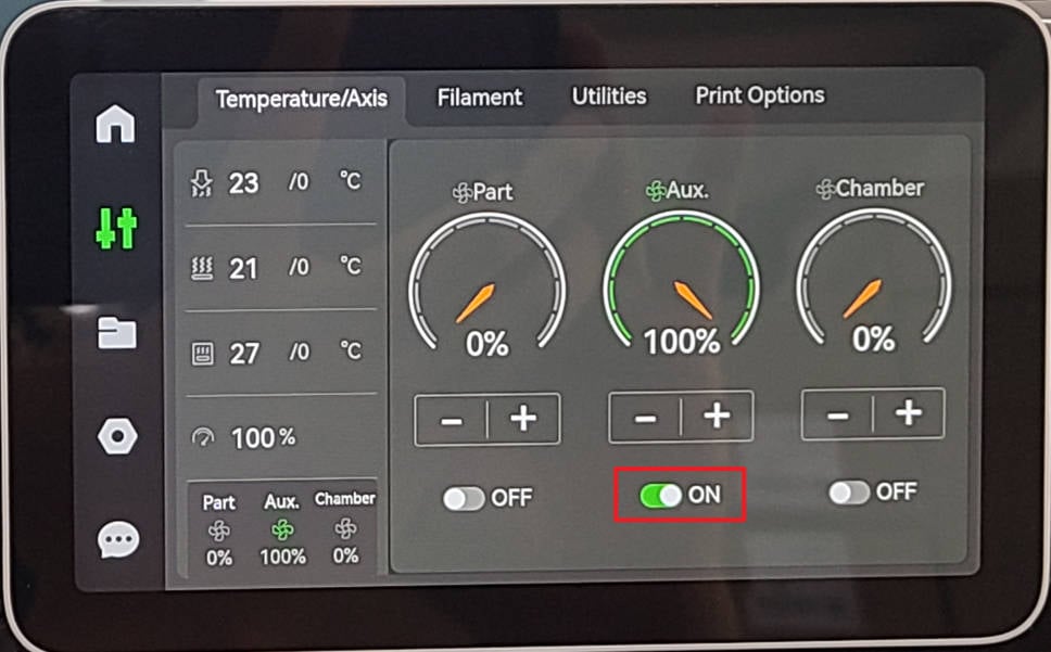
1. Connect power to the the printer, turn on the printer and the screen will light up normally. Turn on the LED light and the aux. part cooling fan, and confirm that the front LED light and the fan can start up and shut down normally;
 |
 |
2. Check the sleep button function, press the sleep button, and confirm that the screen can be turned off and on.
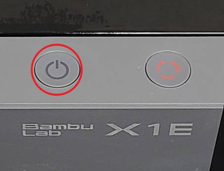
If the test fails, please check all connections again and try again. If that still doesn't work, please contact the Bambu Lab service team.
¶ Calibration step after the operation
After this operation, please perform a calibration procedure to ensure everything works as expected.
¶ End Notes
We hope that the detailed guide we shared with you was helpful and informative.
We want to ensure that you can perform it safely and effectively. If you have any concerns or questions regarding the process described in this article, we encourage you to reach out to our friendly customer service team before starting the operation. Our team is always ready to help you and answer any questions you may have.
Click here to open a new ticket in our Support Page.
We will do our best to respond promptly and provide you with the assistance you need.