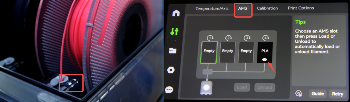
¶ Issue Phenomenon:
When connecting the AMS to the X1 series printer, the LEDs in all four slots were blinking red(If the AMS firmware version is too old, white lights may be blinking). Inserting the filament into the AMS, the AMS preloads (feeds the filament forward and then pulls back), but there is no AMS tab on the printer screen.
¶ Operational guide
First please TURN OFF the printer, and then follow the steps below to troubleshoot.
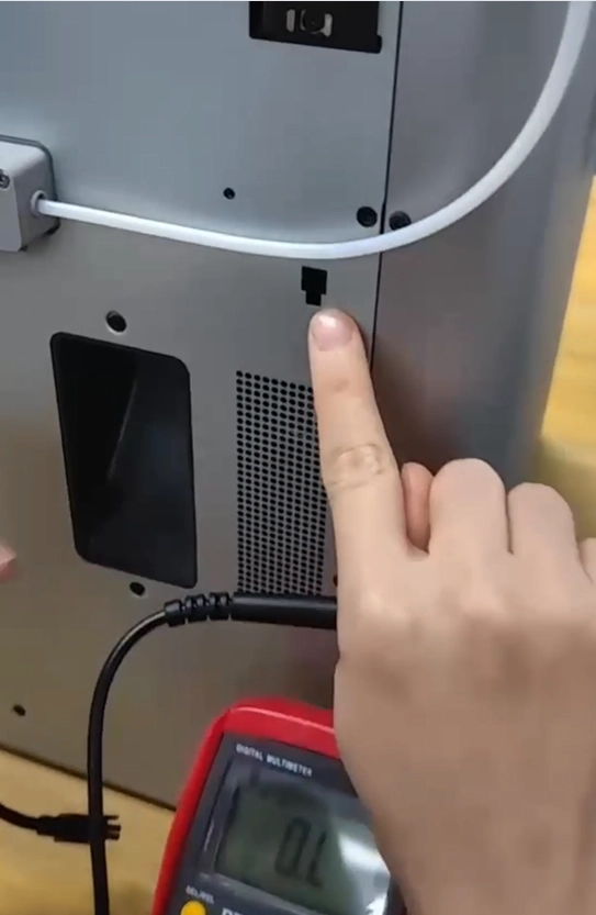
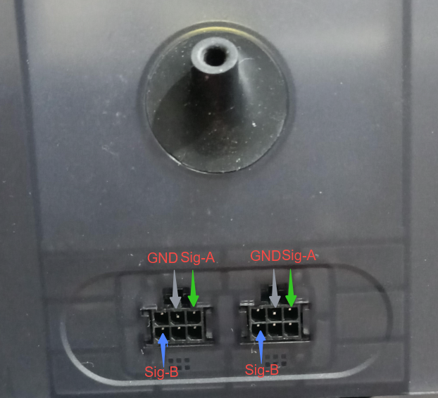
¶ 1. Pin check
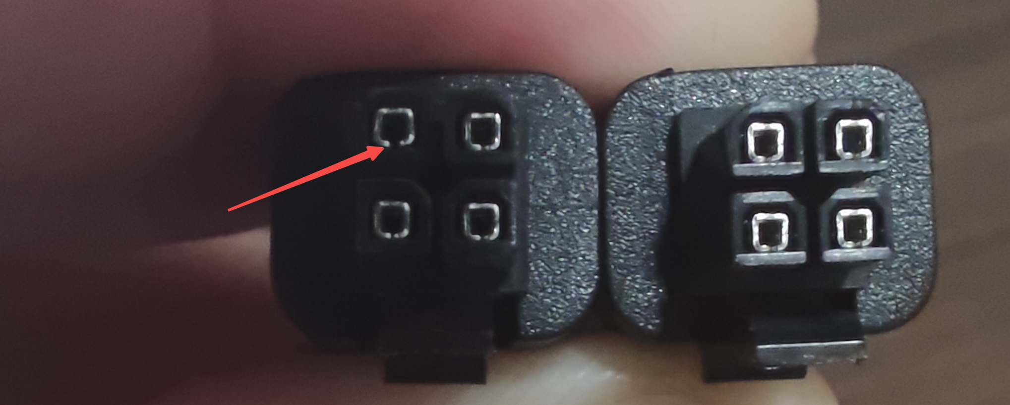
First, you can try to reinsert or replug the 4&6Pin cables.
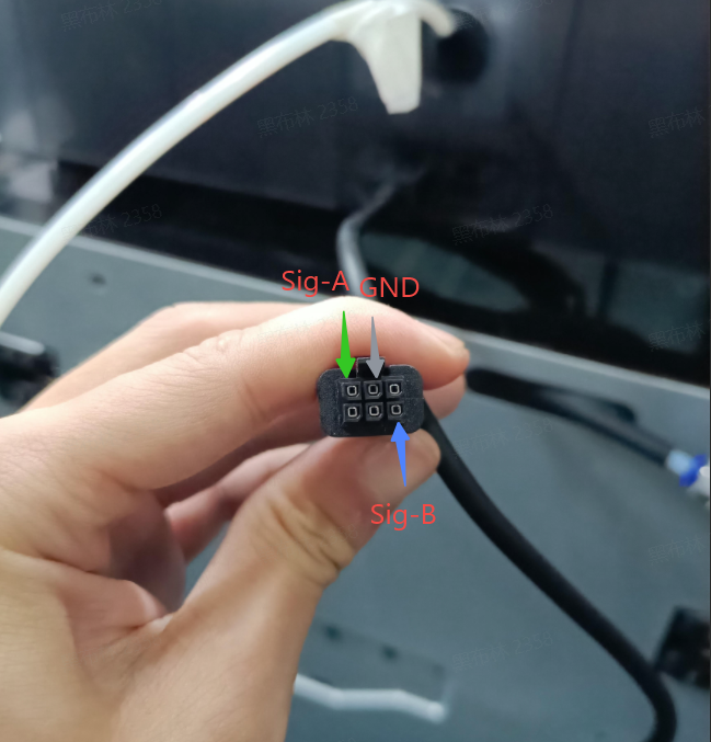
Check whether the Pins of the Bambu Bus 4Pin&6Pin cable (cables connecting AMS—buffer—printer) are open as below:
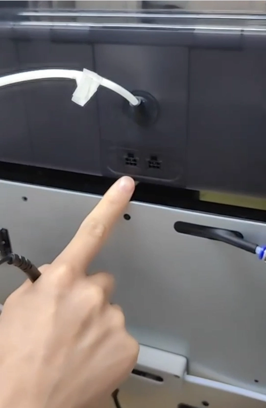
¶ 2. Connection check
- Check if the bus cable inside the AMS is loose.Try to reinsert and re-extract the BUS cable at both ends and power on again to see if it can be restored to normal.
- Check if there is any water ingress corrosion at the pins of the main board.
- It is recommended to shake or bend the 4Pin and 6Pin plugs and cable slightly, or pull out the plugs a little bit (do not pull them out completely) to see if the AMS can be detected for a short time so that we can narrow the fault to the plug/cable;
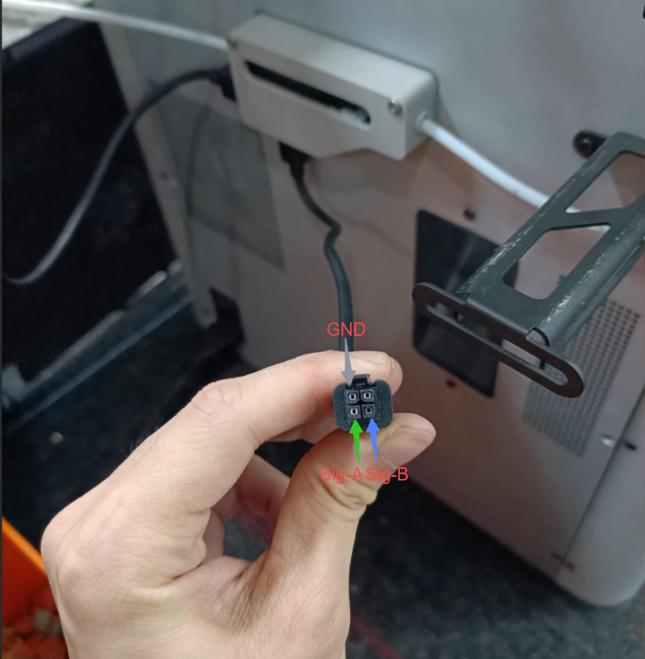
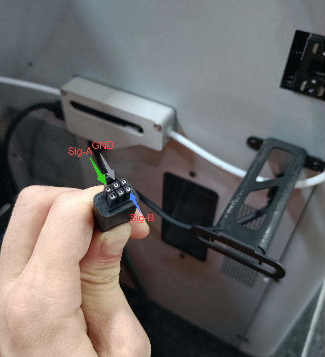
¶ 3. Measure the resistance values
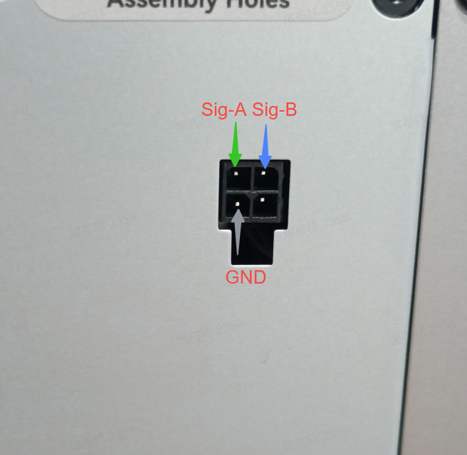
If you have a multimeter, make sure the 4Pin and 6Pin cables are connected properly, then use the multimeter to measure the resistance of the AMS, the printer, and the 4Pin and 6Pin cables(please keep the printer off).

The normal resistance values for X1C, P1P, and P1S (with only one AMS connected) are as follows:
| pin-pin | AMS port | Printer port | 4pin cable connect the buffer | 4pin cable connect the printer | 6pin cable connect the buffer | 6pin cable connect the AMS | 4pin cable connect the AMS Hub | 6pin cables connect the AMS Hub |
| GND-sigA | 4~5kΩ | 4~5kΩ | 4~5kΩ | 4~5kΩ | 4~5kΩ | 4~5kΩ | 2~2.5kΩ | 2~2.5kΩ |
| GND-sigB | 4~5kΩ | 4~5kΩ | 4~5kΩ | 4~5kΩ | 4~5kΩ | 4~5kΩ | 2~2.5kΩ | 2~2.5kΩ |
| sigA-sigB | 8~10kΩ | 8~10kΩ | 8~10kΩ | 8~10kΩ | 8~10kΩ | 8~10kΩ | 4~5kΩ | 4~5kΩ |
The normal resistance values for X1E (with only one AMS connected) are as follows:
| pin-pin | AMS port | Printer port | 4pin cable connect the buffer | 4pin cable connect the printer | 6pin cable connect the buffer | 6pin cable connect the AMS | 4pin cable connect the AMS Hub | 6pin cables connect the AMS Hub |
| GND-sigA | 4~5kΩ | 2~2.5kΩ | 4~5kΩ | 2~2.5kΩ | 2~2.5kΩ | 4~5kΩ | 2~2.5kΩ | 2~2.5kΩ |
| GND-sigB | 4~5kΩ | 2~2.5kΩ | 4~5kΩ | 2~2.5kΩ | 2~2.5kΩ | 4~5kΩ | 2~2.5kΩ | 2~2.5kΩ |
| sigA-sigB | 8~10kΩ | 4~5kΩ | 8~10kΩ | 4~5kΩ | 4~5kΩ | 8~10kΩ | 4~5kΩ | 4~5kΩ |
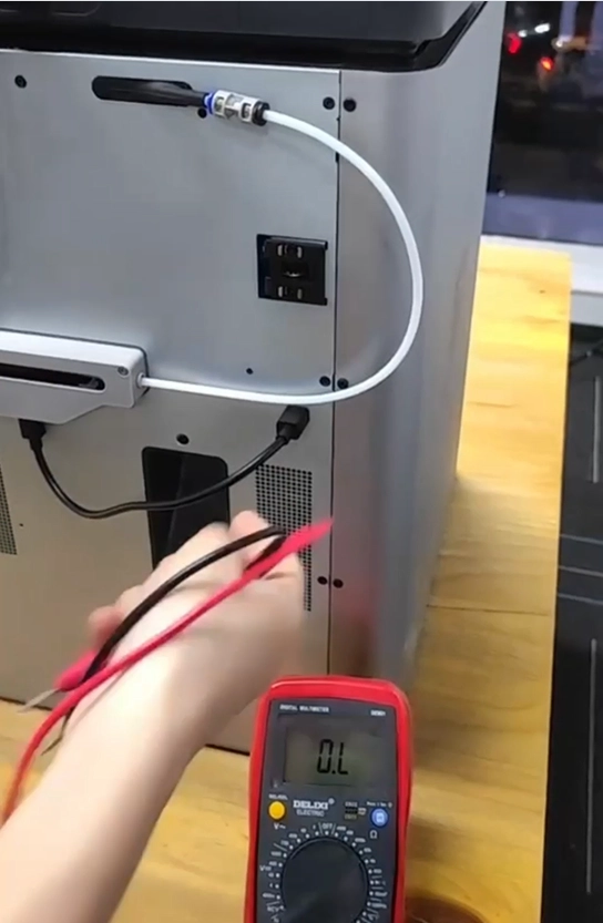
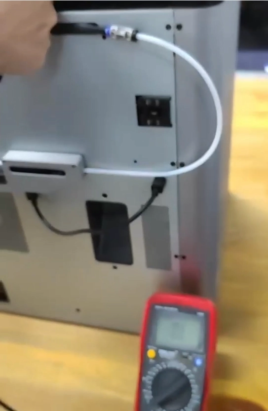
¶ Measure the resistance of both ends of the 4Pin port on the printer and the 4pin cable.
- 4Pin port:
Disconnect the 4Pin cable from the printer and measure the resistance of the printer's 4Pin interface and 4Pin cable, as shown below.
 |
 |
The normal resistance measurement results for the 4Pin port on the printer are as follows:
| Pin-Pin | X1C/P1P/P1S | X1E |
| GND-sigA | 4~5kΩ | 2~2.5kΩ |
| GND-sigB | 4~5kΩ | 2~2.5kΩ |
| sigA-sigB | 8~10kΩ | 4~5kΩ |
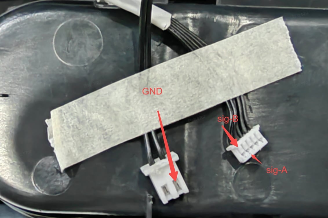
2. 4Pin cable connected to the buffer:
Measure the resistance at the other end of the printer 4Pin cable when it is connected to the buffer.
 |
 |
The normal resistance measurement results for the 4Pin cable connected to the buffer are as follows:
| Pin-Pin | X1C/P1P/P1S | X1E |
| GND-sigA | 4~5kΩ | 4~5kΩ |
| GND-sigB | 4~5kΩ | 4~5kΩ |
| sigA-sigB | 8~10kΩ | 8~10kΩ |
3. 4Pin cable connected to the printer:
Connect the 4Pin cable back to the printer, unplug the 4Pin cable from the buffer, and continue to measure the resistance of the 4Pin cable at the other end (removing the buffer from the printer makes it easier to unplug the cable).
The normal resistance measurement results for the 4Pin cable connected to the printer are as follows:
| Pin-Pin | X1C/P1P/P1S | X1E |
| GND-sigA | 4~5kΩ | 2~2.5kΩ |
| GND-sigB | 4~5kΩ | 2~2.5kΩ |
| sigA-sigB | 8~10kΩ | 4~5kΩ |
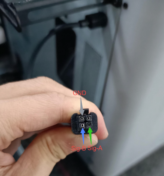
¶ Measure the resistance of both ends of the 6pin port on the AMS and the 6pin cable.
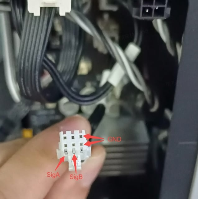
- 6Pin port:
Connect the 4Pin cable back to the buffer, unplug the 6Pin cable from the AMS, and measure the resistance of the AMS 6Pin port (both ports are the same) and the 6Pin cable.
 |
 |
The normal resistance measurement results for the 6Pin port on the AMS are as follows:
| Pin-Pin | X1C/P1P/P1S | X1E |
| GND-sigA | 4~5kΩ | 4~5kΩ |
| GND-sigB | 4~5kΩ | 4~5kΩ |
| sigA-sigB | 8~10kΩ | 8~10kΩ |
2. 6Pin cable connected to the buffer:
 |
 |
The normal resistance measurement results for the 6Pin cable connected to the buffer are as follows:
| Pin-Pin | X1C/P1P/P1S | X1E |
| GND-sigA | 4~5kΩ | 2~2.5kΩ |
| GND-sigB | 4~5kΩ | 2~2.5kΩ |
| sigA-sigB | 8~10kΩ | 4~5kΩ |
3. 6Pin cable connected to the AMS:
Finally, unplug the 6Pin cable from the buffer and measure the resistance at the other end of the 6Pin cable (removing the buffer from the printer makes it easier to unplug the cable).
The normal resistance measurement results for the 6Pin cable connected to the AMS are as follows:
| Pin-Pin | X1C/P1P/P1S | X1E |
| GND-sigA | 4~5kΩ | 4~5kΩ |
| GND-sigB | 4~5kΩ | 4~5kΩ |
| sigA-sigB | 8~10kΩ | 8~10kΩ |
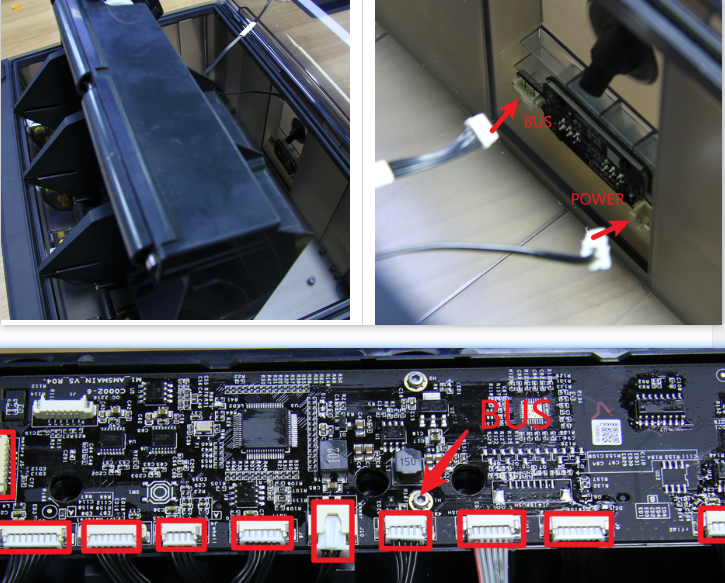
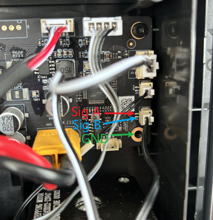
¶ Measure the resistance between the AMS mainboard and the MC board.
If an abnormal resistance value is measured in the above steps, you can determine where in the AMS/printer/4&6pin cable/buffer the fault is causing the AMS to be undetectable.
Measure the resistance of the AMS mainboard
If the resistance of the AMS 6pin port is abnormal, you can disassemble AMS (please refer to this wiki) and further measure the resistance of the pins of the Bus and power cables connected to the mainboard to see whether the mainboard is faulty:
The normal resistance measurement results for the bus and power cable are as follows:
| Pin-Pin | X1C/P1P/P1S | X1E |
| GND-sigA | 4~5kΩ | 4~5kΩ |
| GND-sigB | 4~5kΩ | 4~5kΩ |
| sigA-sigB | 8~10kΩ | 8~10kΩ |
- If the resistance measured on the bus and power cable port connected to the mainboard is normal, it may indicate a faulty AMS power board that needs to be replaced.
- If the resistance measured on the bus and power cable port connected to the mainboard is abnormal, it may indicate a faulty AMS mainboard.
Measure the resistance of the MC board
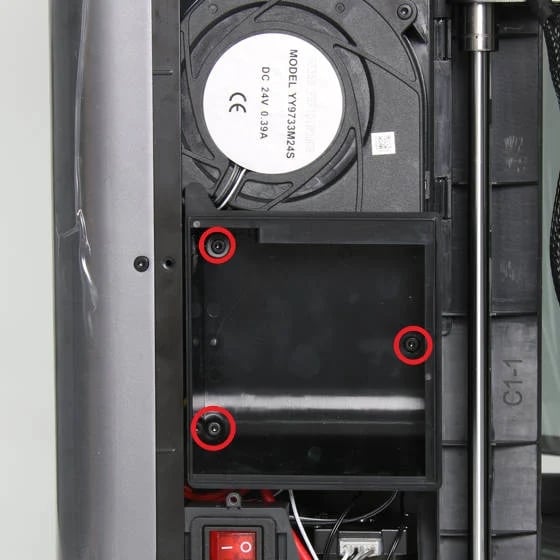
If the measured resistance of the printer's 4pin port is abnormal, it may be the fault of the AMS interface board or the MC board. You can remove the back cover of the printer, unplug the 6pin cable from the AMS interface board (please refer to this wiki), and measure the resistance of the 6pin cable connected to the MC board to see whether the MC board is faulty:
The normal resistance measurement results for the 6pin cable connected to the MC board are as follows:
| Pin-Pin | X1C/P1P/P1S | X1E |
| GND-sigA | 4~5kΩ | 4~5kΩ |
| GND-sigB | 4~5kΩ | 4~5kΩ |
| sigA-sigB | 8~10kΩ | 8~10kΩ |
- If the resistance measured on the 6pin cable connected to the MC board is normal, it may indicate a faulty AMS interface board that needs to be replaced.
- If the resistance measured on the 6pin cable connected to the MC board is abnormal, it may indicate a faulty MC board that needs to be replaced.
For X1E, if the resistance measurements mentioned above are all normal, please refer to the following images. First, remove the air duct (left image), and then measure the resistance of the Network interface and AMS interface board port on the heating module control board(right image).
 |
 |
The normal resistance measurement results for the Network interface and AMS interface board port on the heating module control board are as follows:
| Pin-Pin | X1E |
| GND-sigA | 4~5kΩ |
| GND-sigB | 4~5kΩ |
| sigA-sigB | 8~10kΩ |
If the measured resistance is abnormal, it may indicate a need to replace the heating module control board.
¶ Note
There are a total of 8 sets of resistance value data above, as shown in the following figure. If the measured resistance value of any part is abnormal, it indicates that this part is faulty. Please measure and record them with reference to the following picture, and then contact the customer support team for assistance.
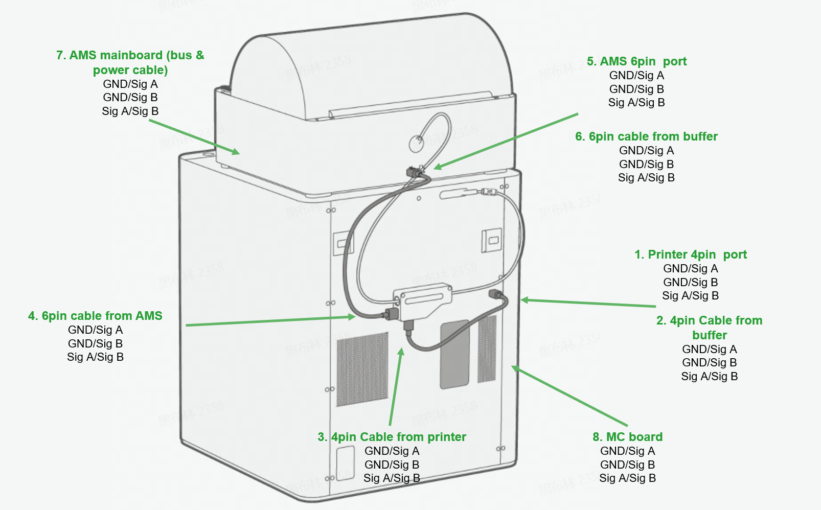
Here is a sample table for recording resistance measurements:
| pin-pin | AMS port | Printer port | 4pin cable connect the buffer/AMS hub | 4pin cable connect the printer | 6pin cable connect the buffer/AMS hub | 6pin cable connect the AMS | MC board | AMS mainboard |
| GND-sigA | ||||||||
| GND-sigB | ||||||||
| sigA-sigB |