¶ When to use?
- The printer prompts "Filament failed to send to the extruder", but there is filament in the tube above the toolhead.
- When printing with AMS or AMS Lite, the printer prompts "Please pull out the filament from the external spool", but there is no filament in the tube above the toolhead.
- The printer prompts "Please insert the filament into the port until it can no longer be pushed.", but the filaments have entered the extruder.
¶ Tools and materials needed
- One piece of filament
- (Optional) H1.5 & H2.0 Allen key
- (Optional) Flat-tipped tweezers
¶ X/P Series
¶ Inspection Guide
¶ Step 1: Remove the tube
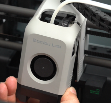
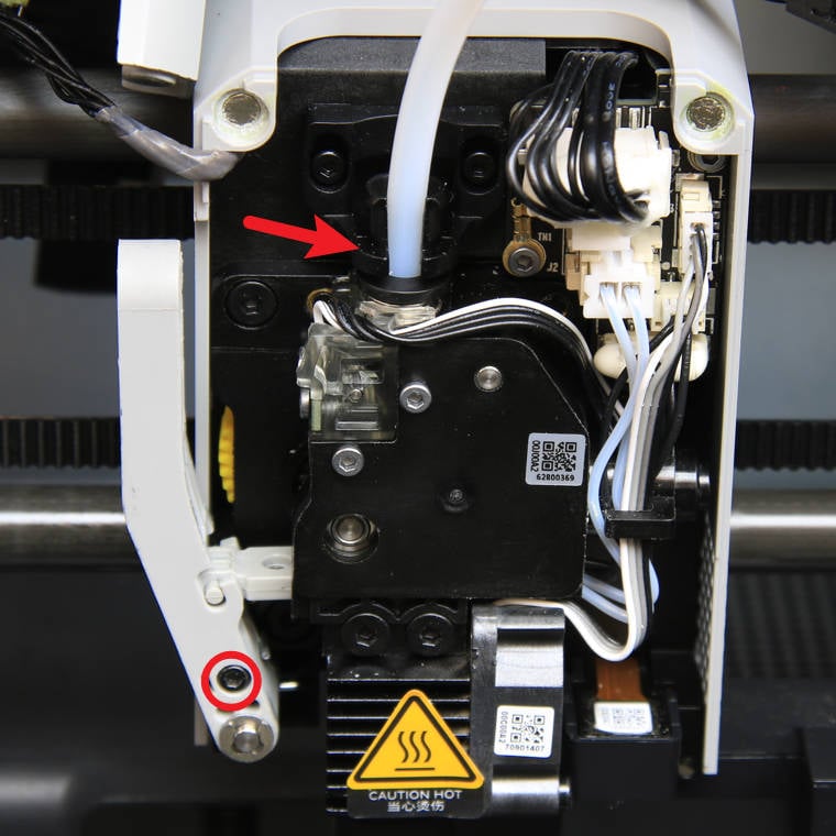
Turn off the printer, open the front housing, and hang it over the carbon rod. Press the tube bracket to disconnect the PTFE tube.
 |
 |
¶ Step 2: Manual Loading
Try manual loading using a piece of filament.
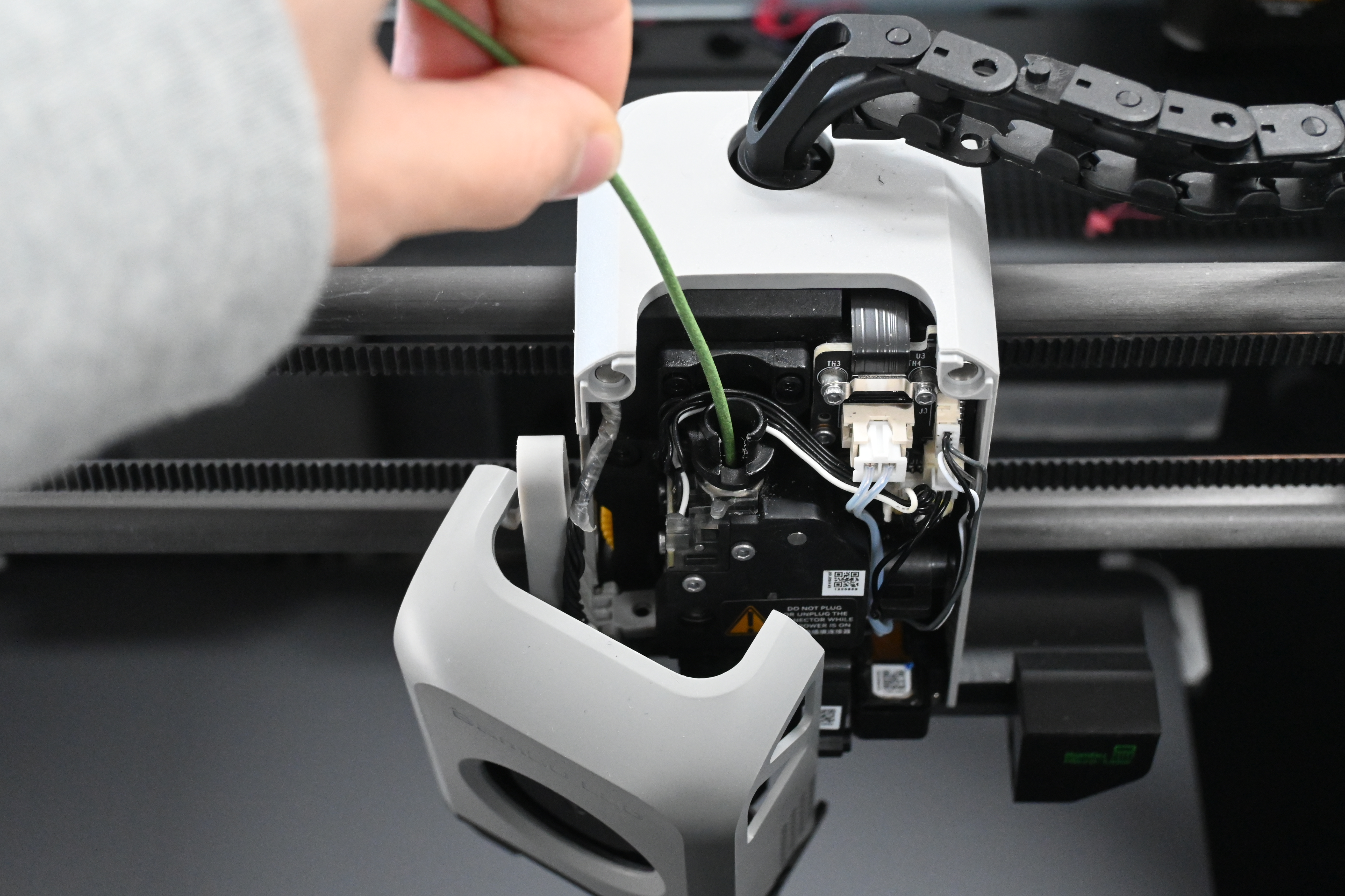
¶ Step 3: Observe the screen
- Click the Controls icon on the screen and observe the small green dot.
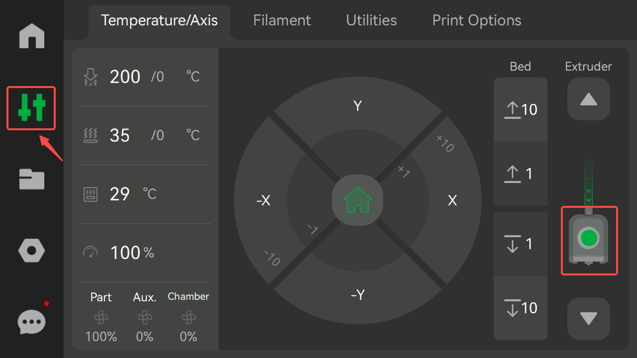
The P1 series requires you to observe the green dot in the center of the arrow's pointing direction on a computer or mobile device.
.png)
- After inserting the filament, observe whether a small green dot appears on the extruder icon; then remove the filament and observe whether a small white dot appears on the extruder icon.
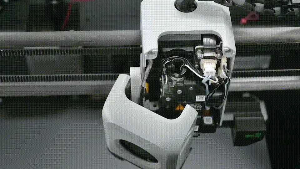
- If both the green and white displays are normal, the filament sensor is normal. If not, please refer to the following method for troubleshooting.
¶ Disassembly Guide
¶ Step 1: Disconnect the cables
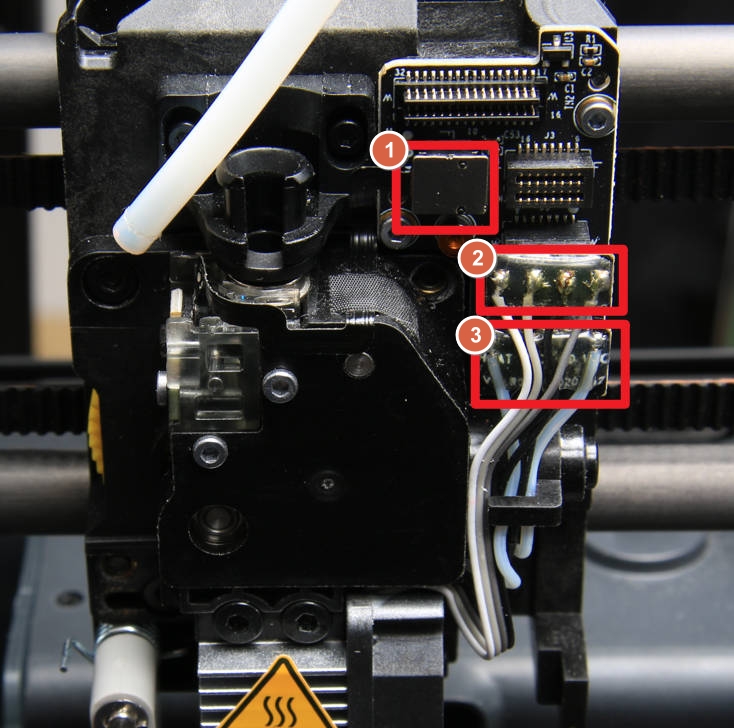
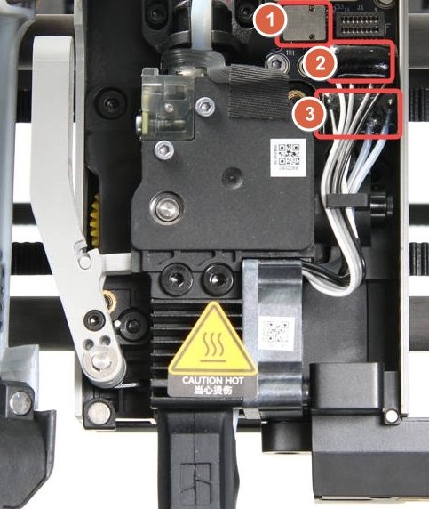
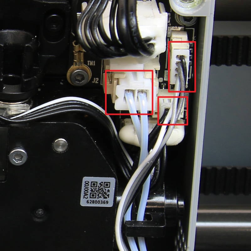
Disconnect the hotend heater, hotend fan, and NTC resistor cables to expose the sensor's connector. Use a hair dryer to heat the silicone glue, then disconnect the cable.
 |
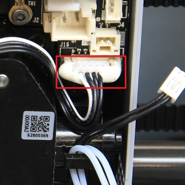 |
Note: The schematic diagram of the P1 series and X1E interface is as follows: 1. filament sensor; 2. Hotend fan; 3. Hotend heater.
P1
X1E
¶ Step 2: Loosen the cutter lever
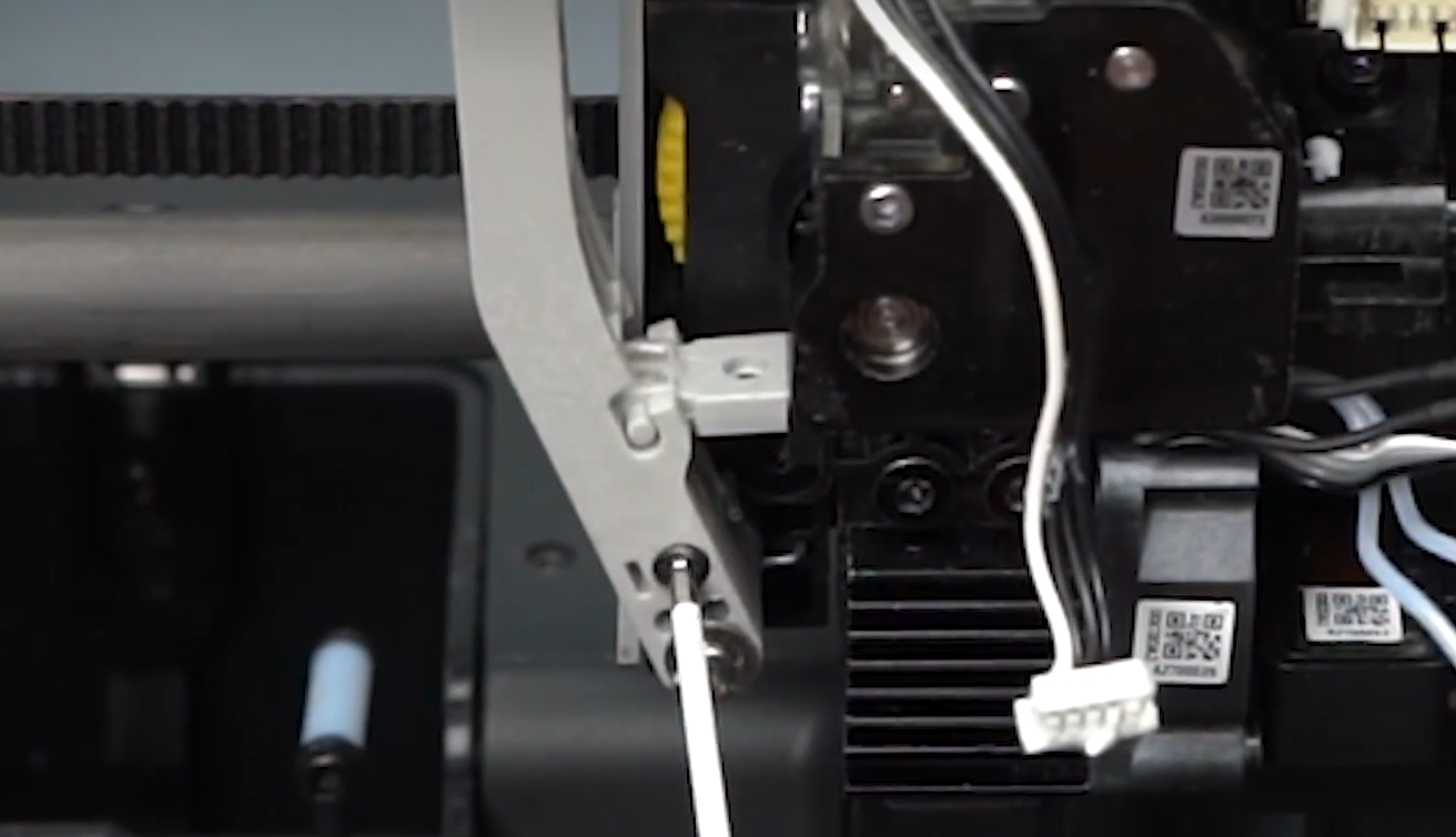
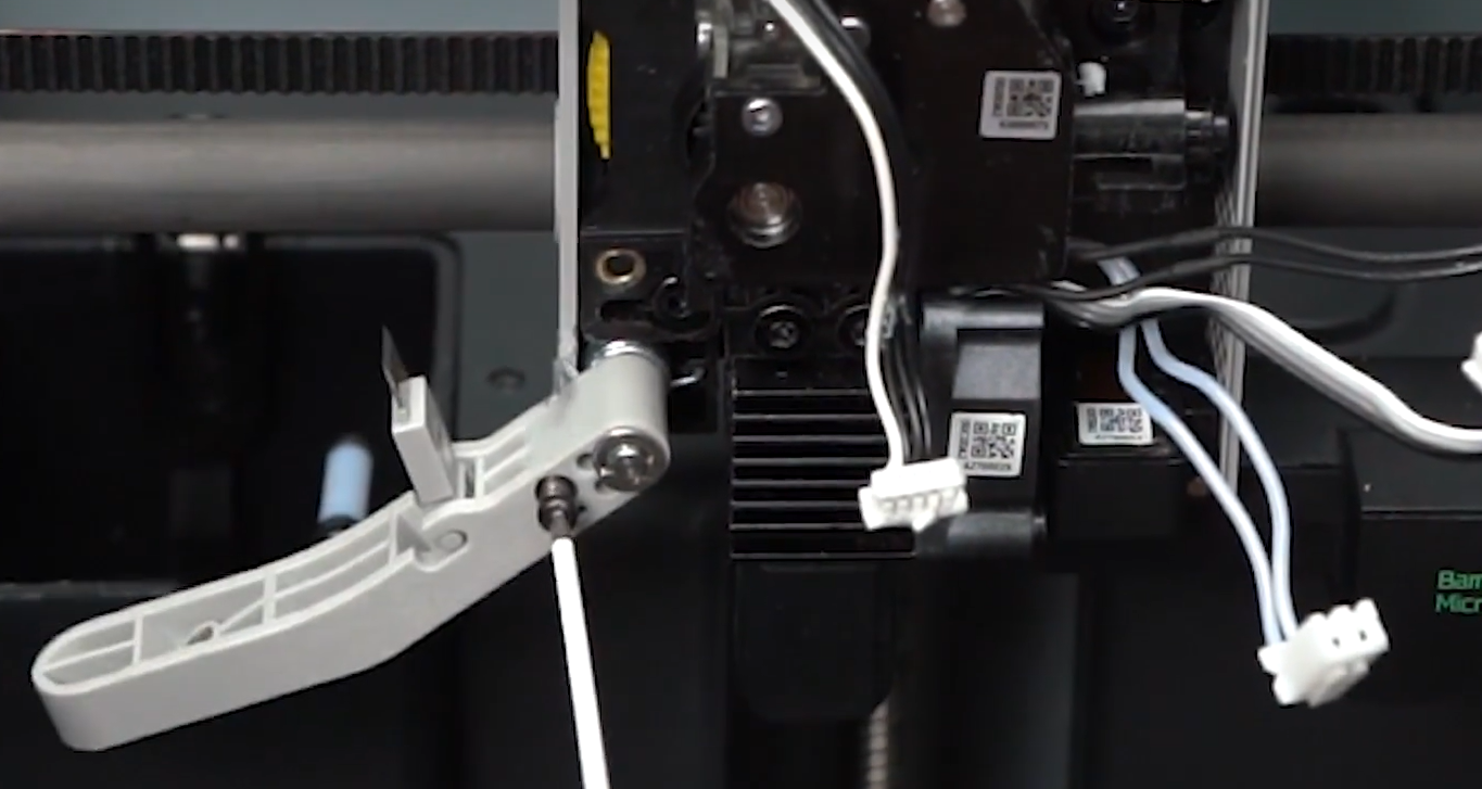
Use the H1.5 Allen key to loosen the screw on the cutter lever and release the lever.
 |
 |
¶ Step 3: Remove the sensor assembly
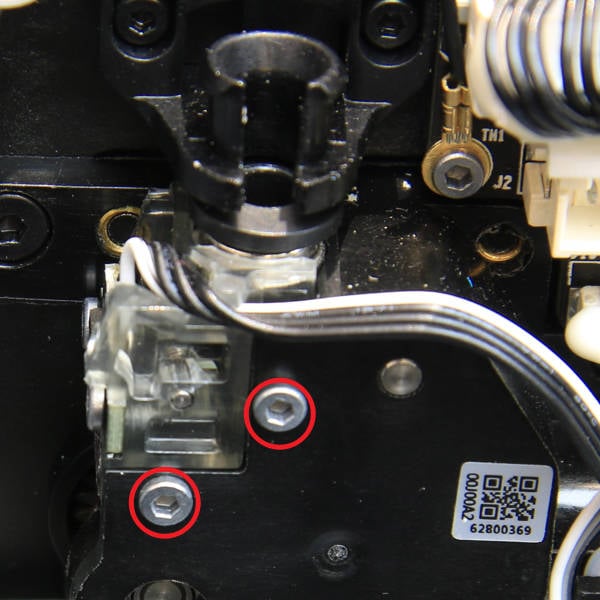
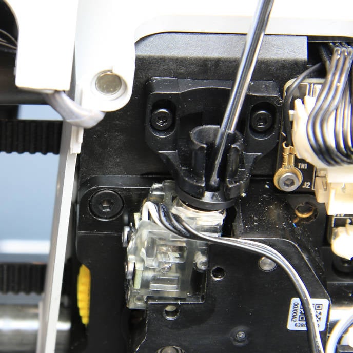
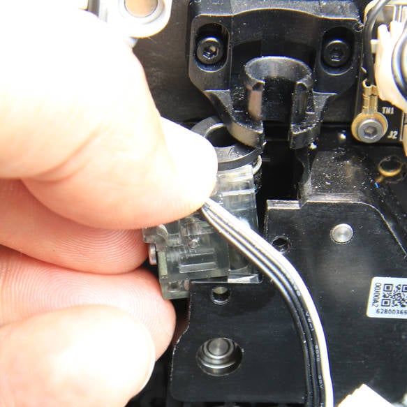
Remove 2 screws using an H1.5 Allen key. Use the hex key to pry the assembly loose from the pneumatic connector, then remove the sensor assembly.
 |
 |
 |
¶ Troubleshooting Guide
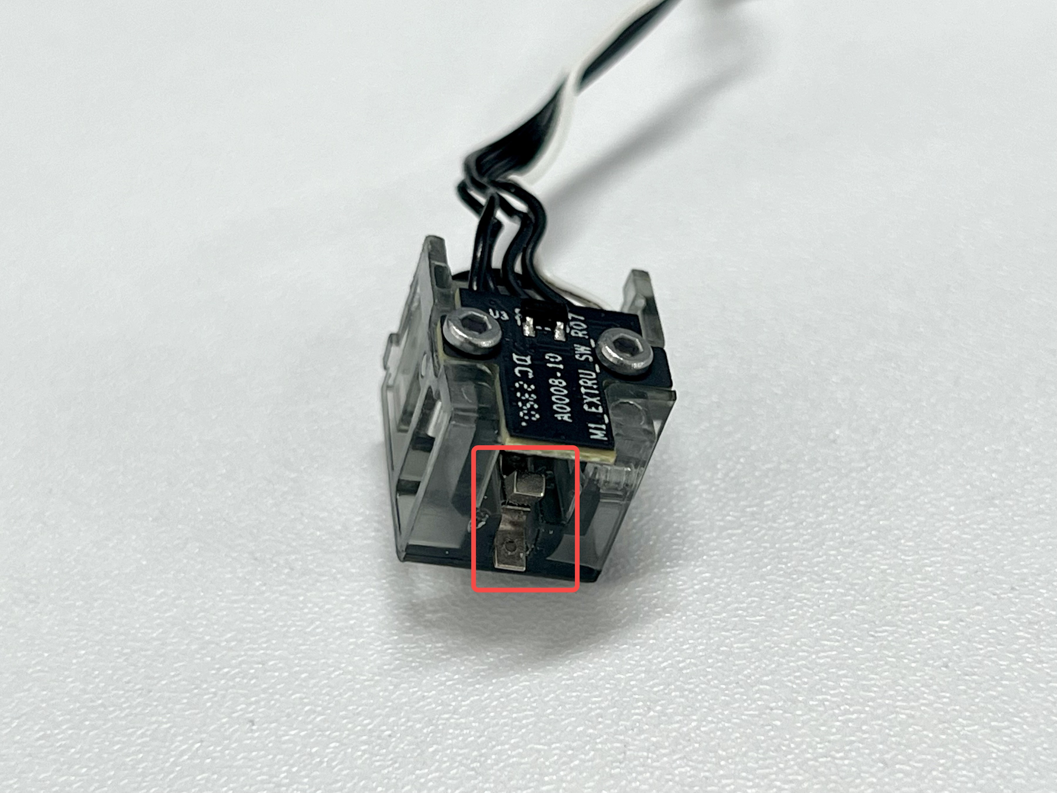
¶ Inspect the inside of the filament sensor
Check if there is any residual filaments stuck inside the filament sensor.
¶ Inspect the arm
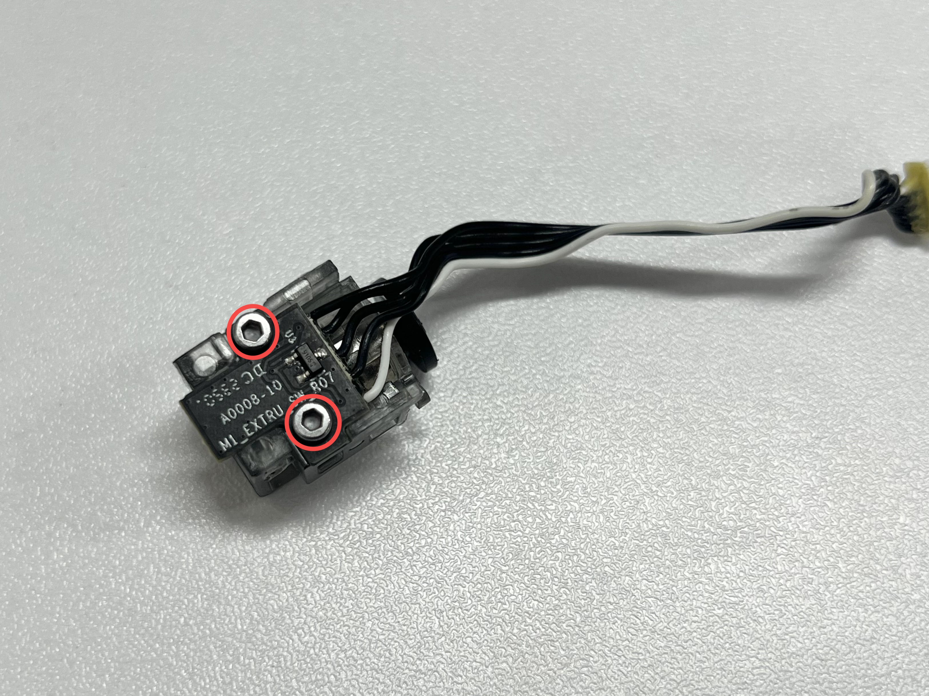
¶ Step 1: Remove the filament sensor
Remove the 2 screws on the filament sensor using an H1.5 Allen key.
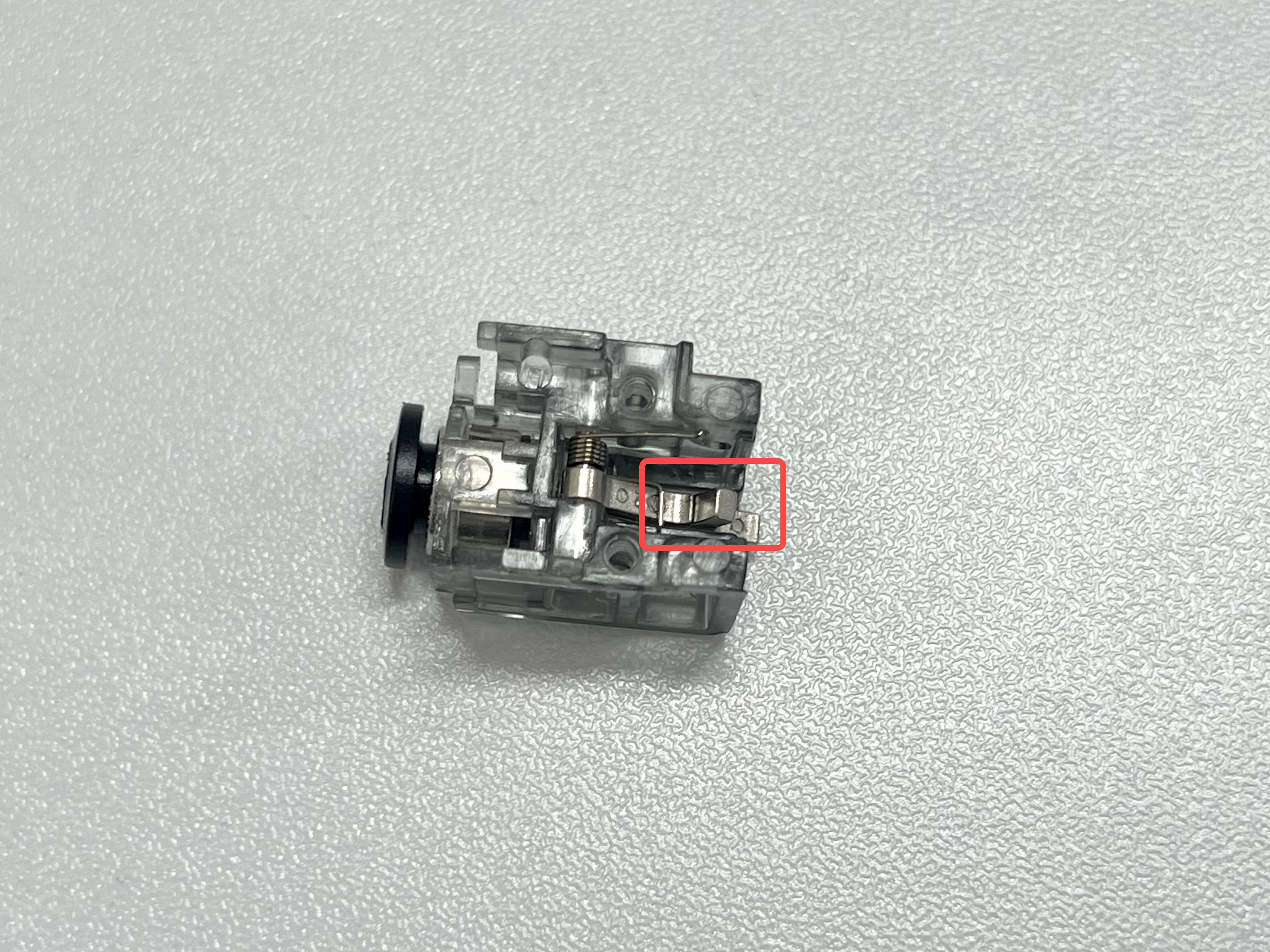
¶ Step 2:Inspect the arm
Insert a piece of filament and observe whether the arm operates normally and whether it returns to its original position automatically after the filament is removed.
 |
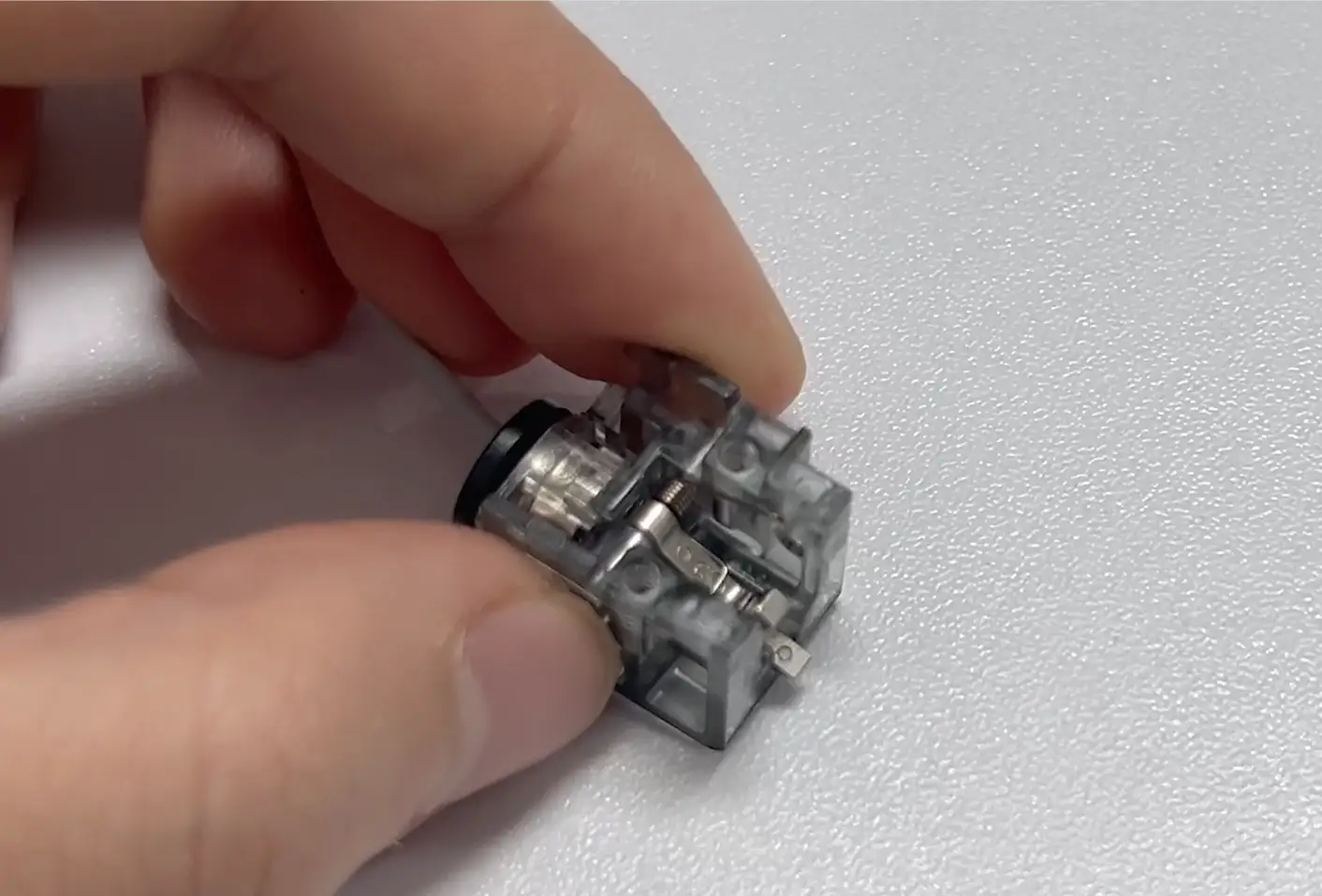 |
If the arm is stuck, move it left or right to return it to its original position.
¶ Assembly Guide
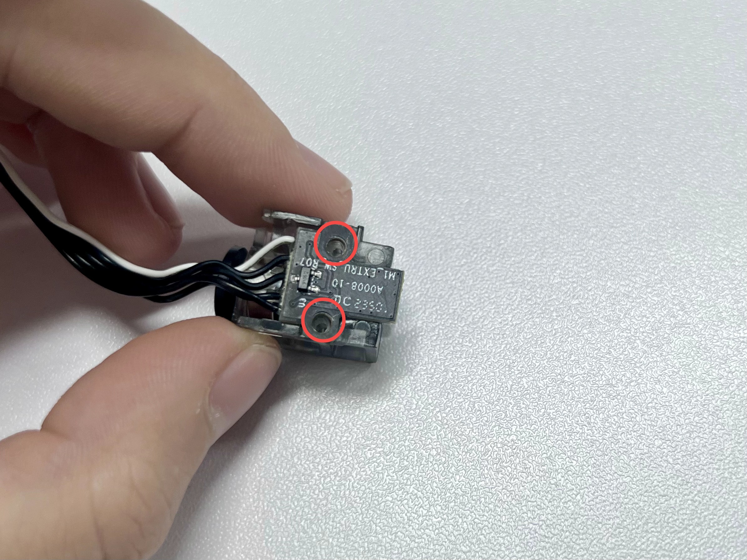
¶ Step 1: Install the filament sensor screws
Use an H1.5 Allen key to install the 2 screws on the filament sensor.
¶ Step 2: Install the filament sensor
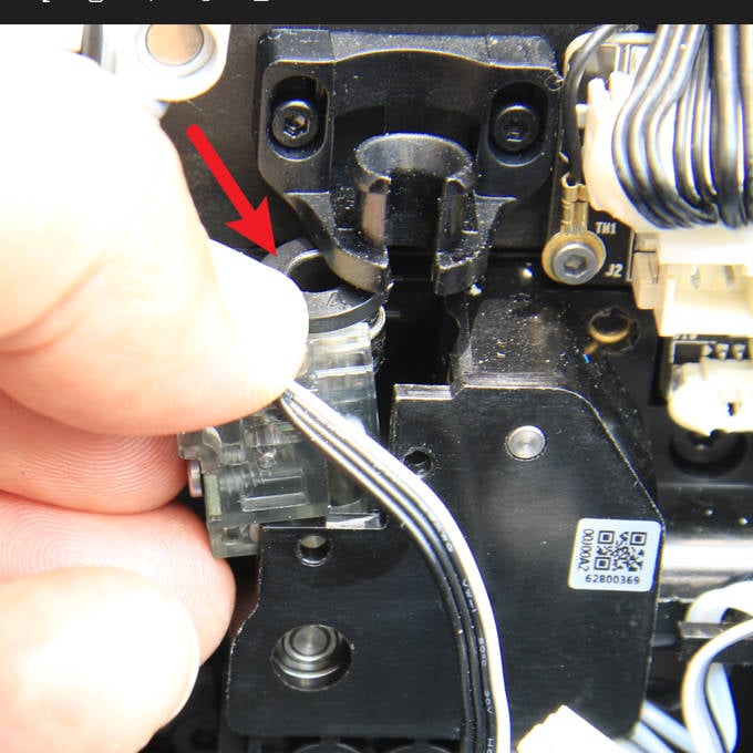
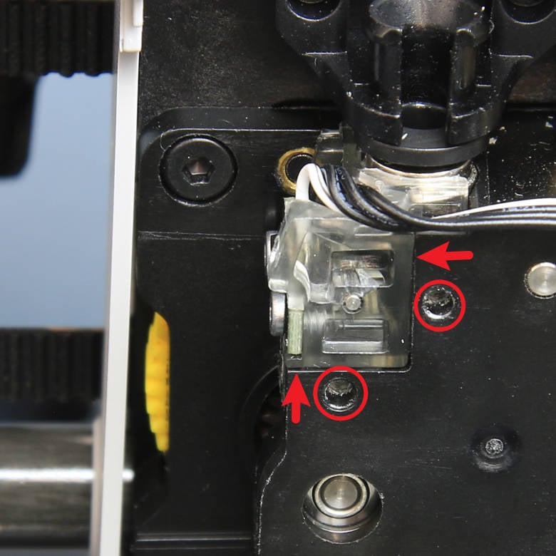
Press the pneumatic connector on the sensor assembly to install it in place, and then lock in 2 screws to secure it.
 |
 |
¶ Step 3: Connect cables
Connect the sensor cable, and it's recommended to use silicone glue to reinforce this connection. Next, pay attention to connect the hotend NTC cable, hotend fan cable and hotend heater cable in sequence, and align the connectors.
 |
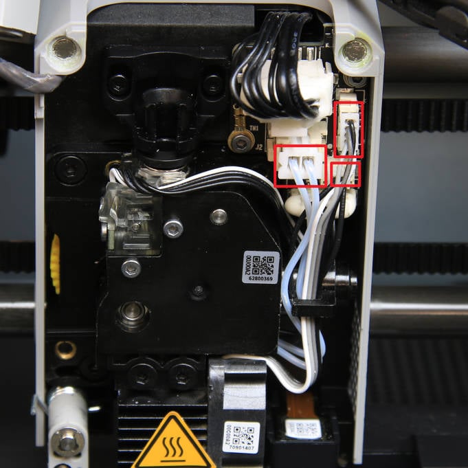 |
Note: The schematic diagram of the P1 series and X1E interface is as follows: 1. Filament sensor; 2. Hotend fan; 3. Hotend heater.
Please make sure that the connector for the filament sensor is correctly installed. If the filament sensor is not working, the first troubleshooting should be to confirm the sensor is inserted as in the picture.
P1
X1E
¶ Step 4: Lock the cutter lever, insert the PTFE tube, and close the front housing
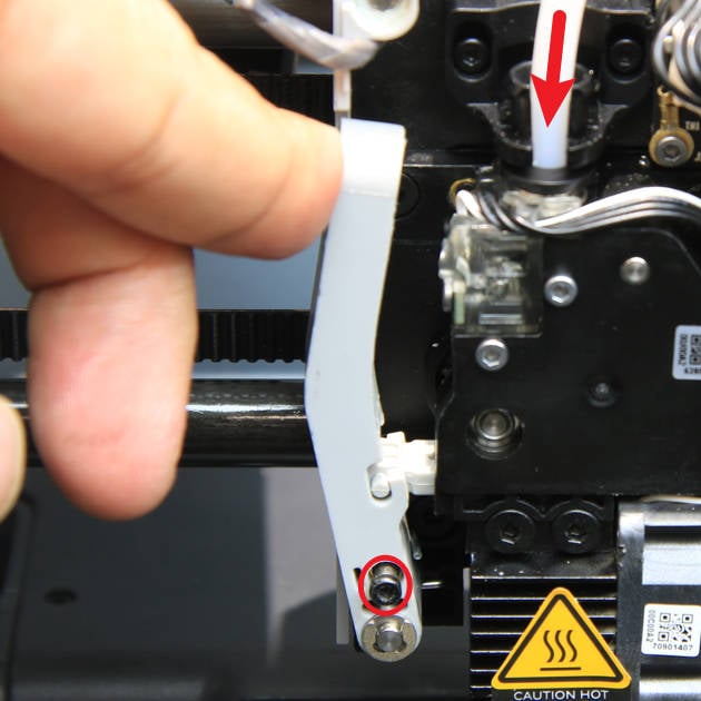
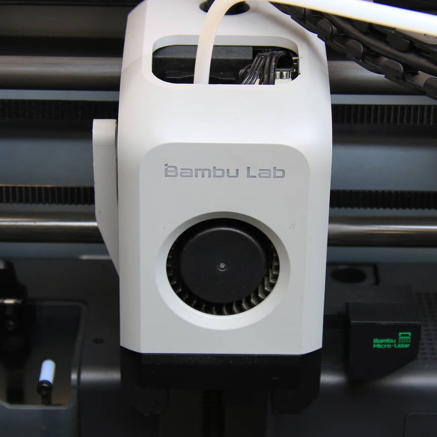
Hold the cutter lever manually, insert the cutter into the slot, tighten the lever screw (screw B), reinsert the PTFE tube, and finally, close the front housing.
 |
 |
¶ A1 Series
¶ Inspection Guide
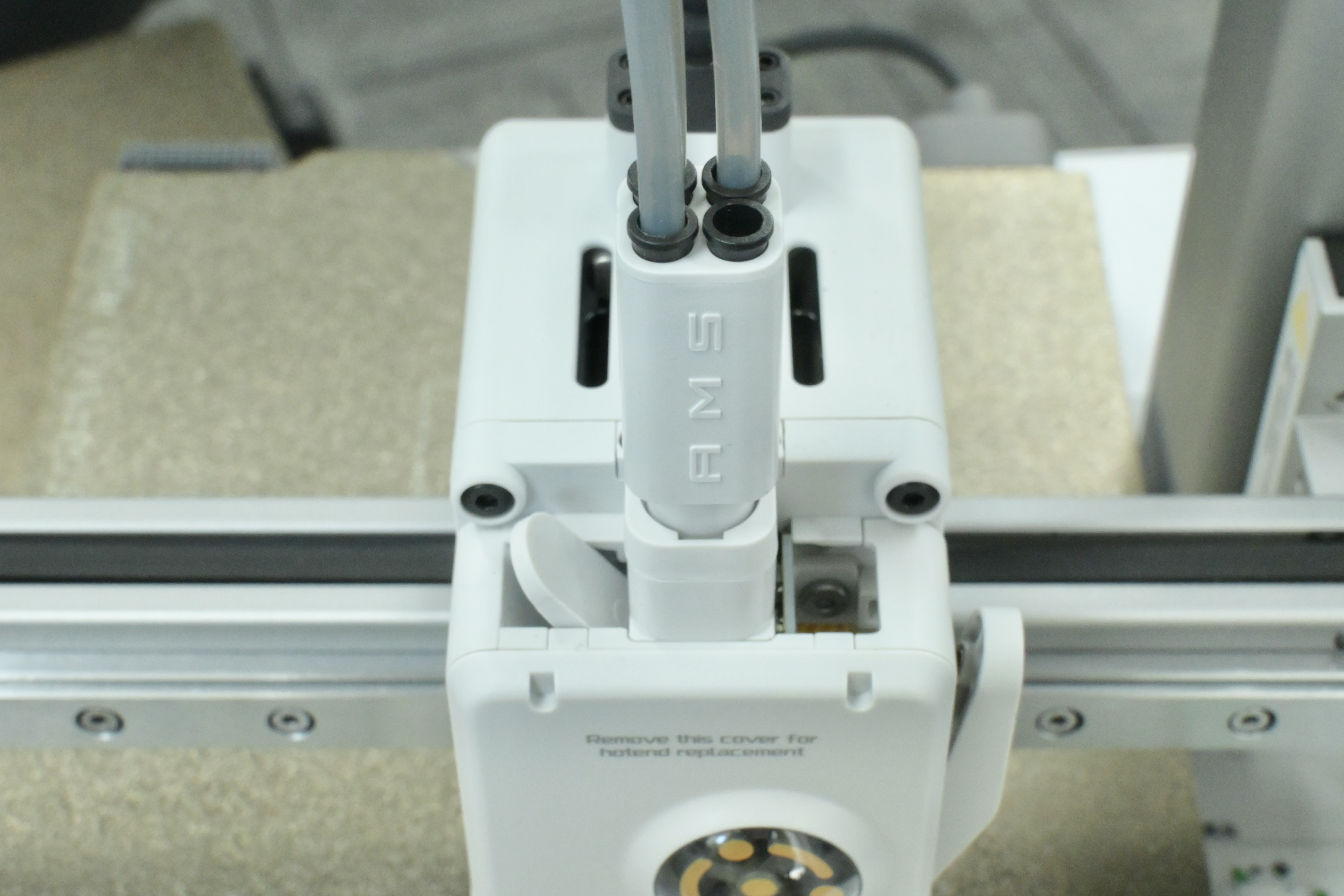
¶ Step 1: Remove the tube
Remove one tube from the filament hub.
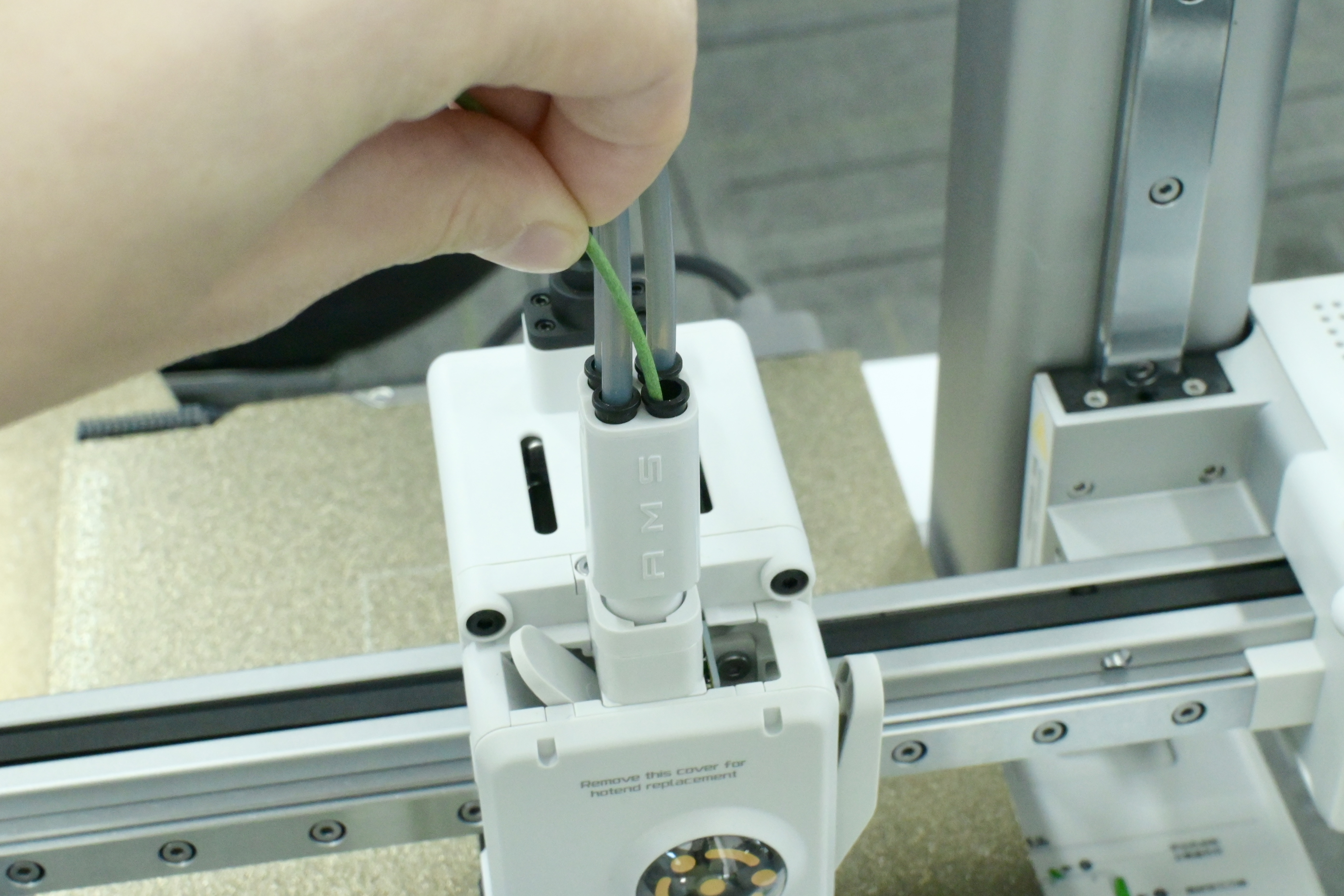
¶ Step 2: Manual Loading
Try manual loading using a piece of filament.
¶ Step 3: Observe the screen
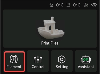
- Click the Controls icon on the screen and observe the small green dot.
 |
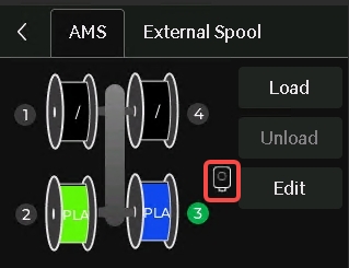 |
- After inserting the filament, observe whether a small green dot appears on the extruder icon; then remove the filament and observe whether a small white dot appears on the extruder icon.
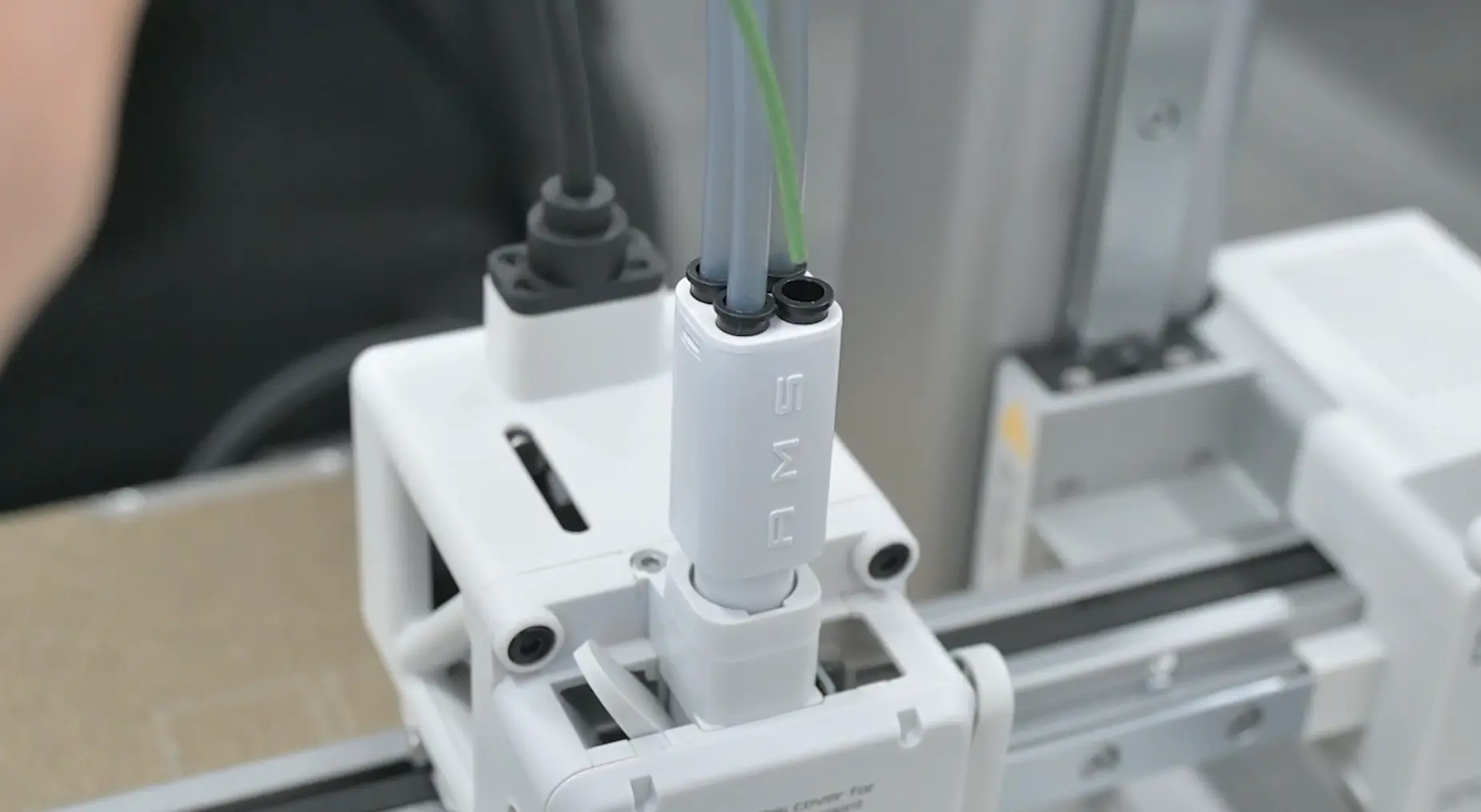
- If both the green and white displays are normal, the Hall sensor is normal. If not, please refer to the following method for troubleshooting.
¶ Disassembly Guide
¶ Step 1: Remove the AMS lite Filament Hub
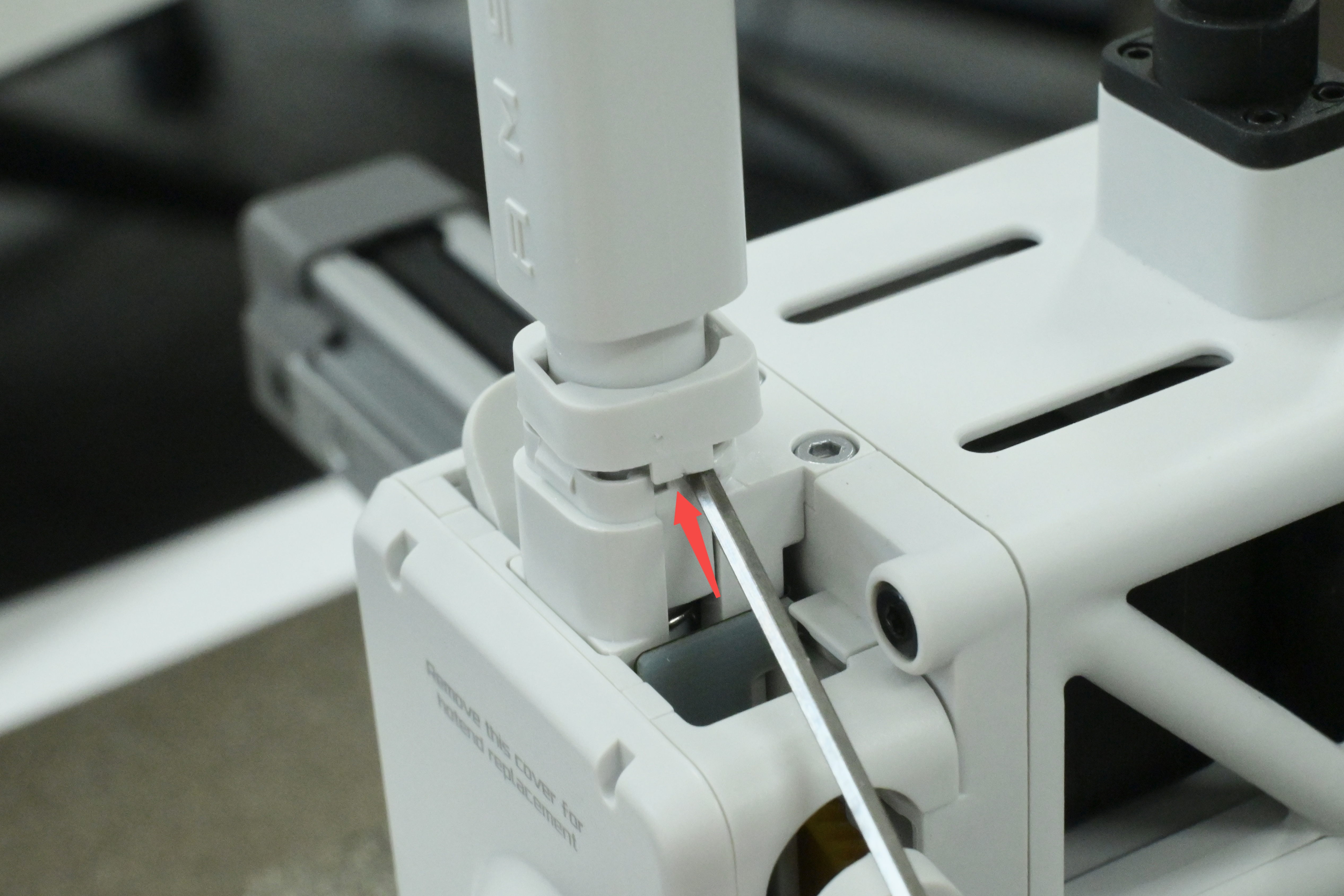
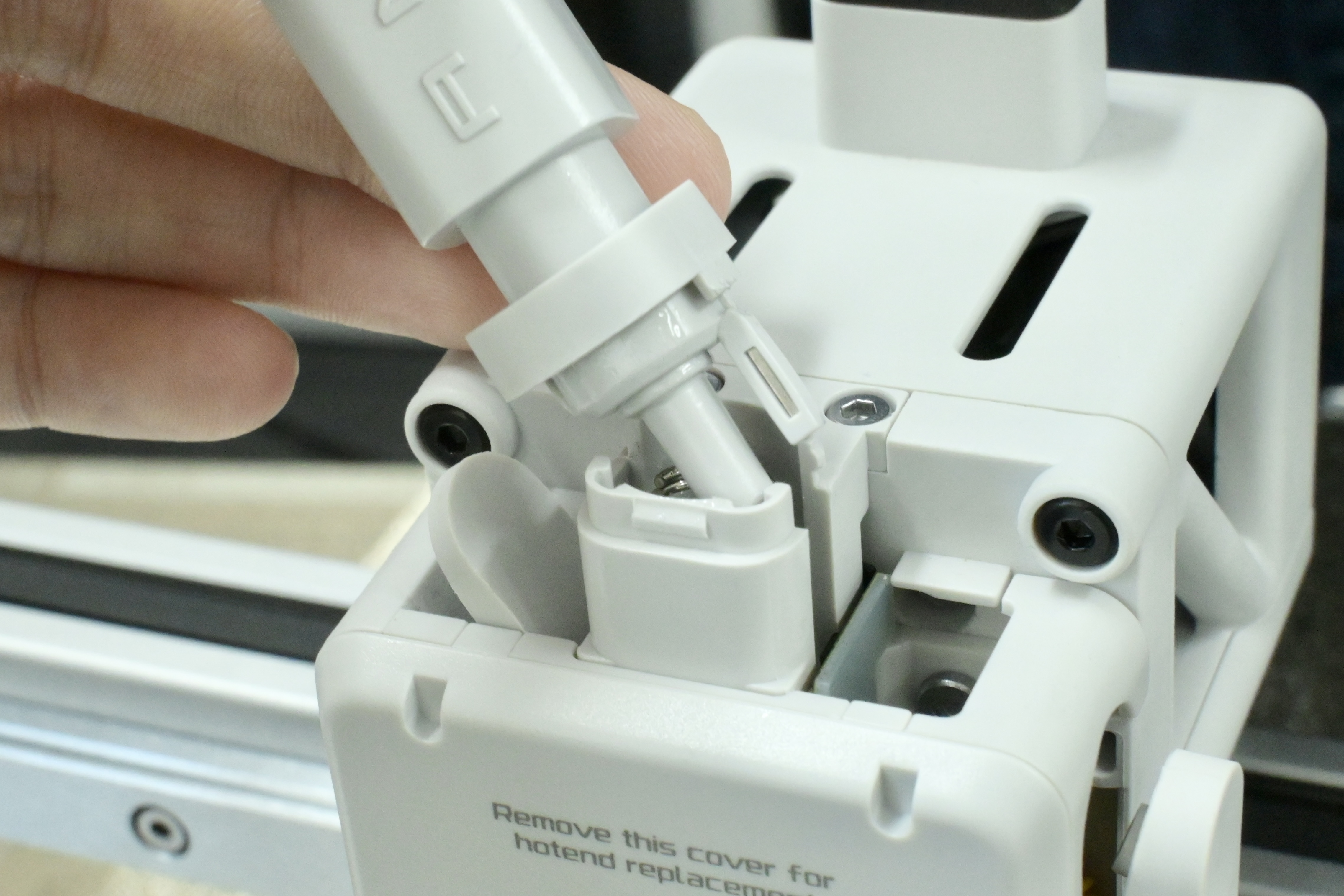
For easier inspection and confirmation, we can remove the Filament Hub. This operation is very simple: use a hex key to slightly pry up the cover, and then the Filaments Hub can be removed.
Note: The base of the filament sensor is coated with damping grease.
 |
 |
¶ Step 2: Disassemble the filament base
- Remove the 2 screws on the top of the filament base using an H2.0 Allen key and remove the filament base.
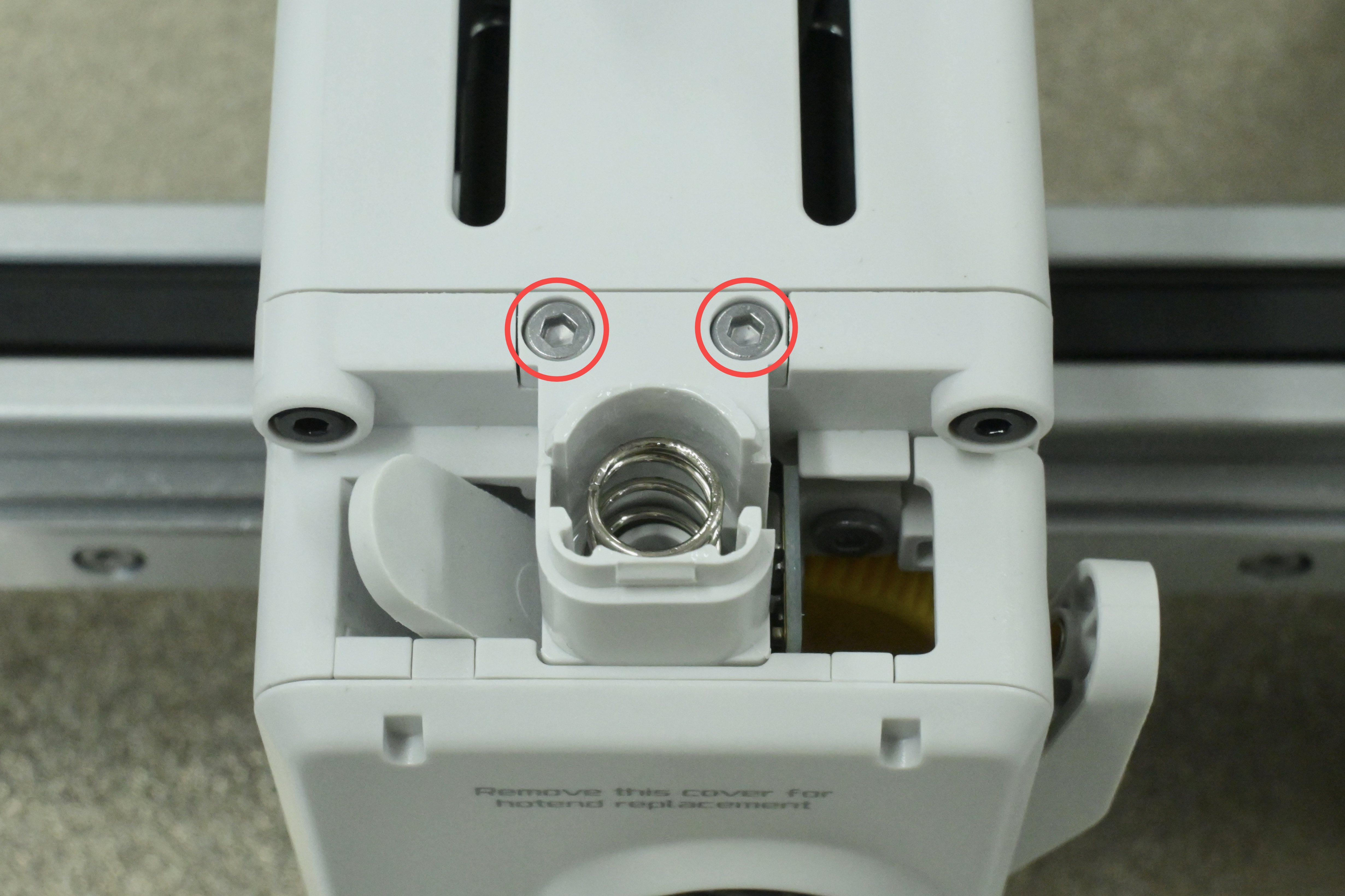
- Remove the bottom.
Note: When removing the base of the Filament Hub, carefully pull it out to avoid damaging the ribbon cable.
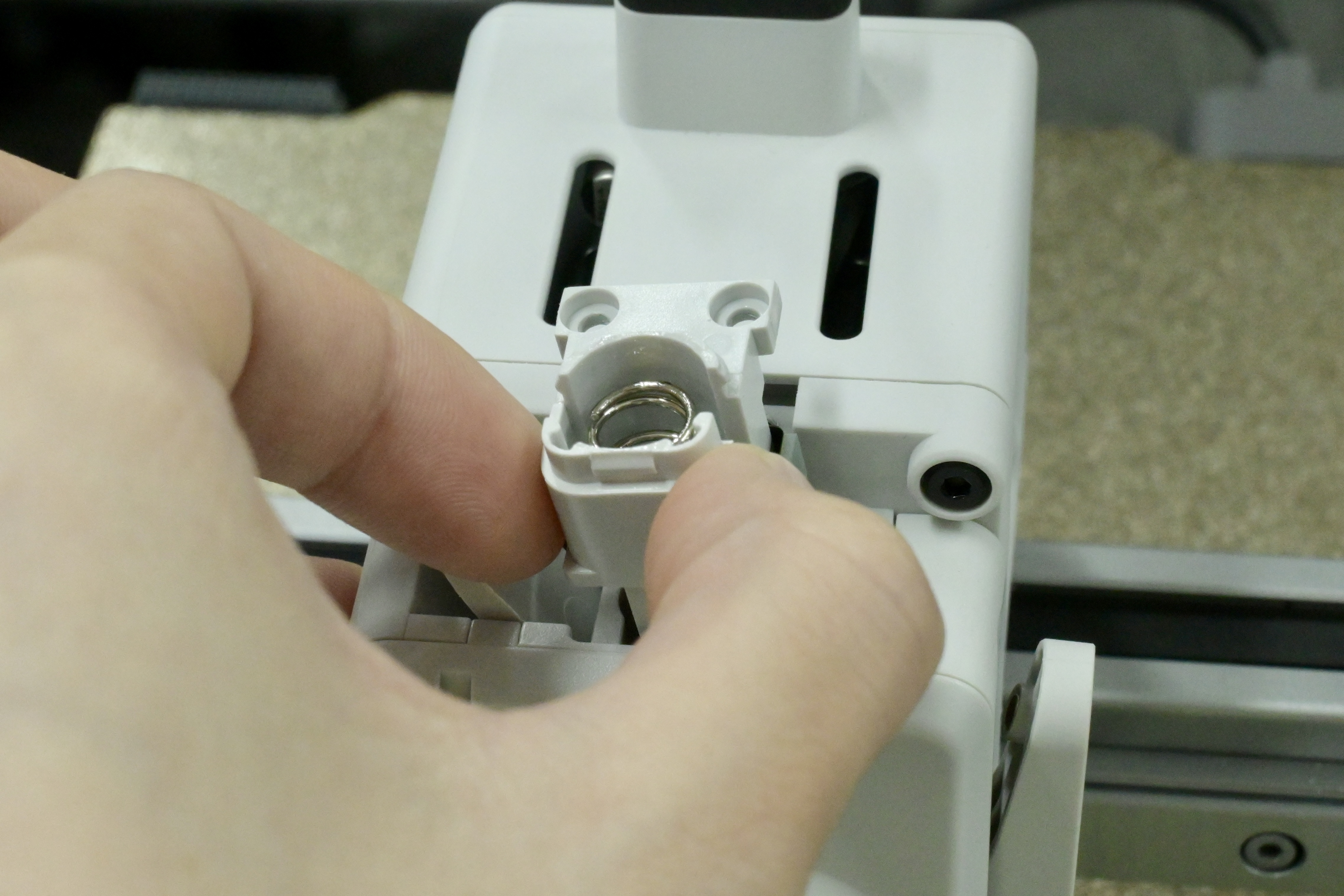 |
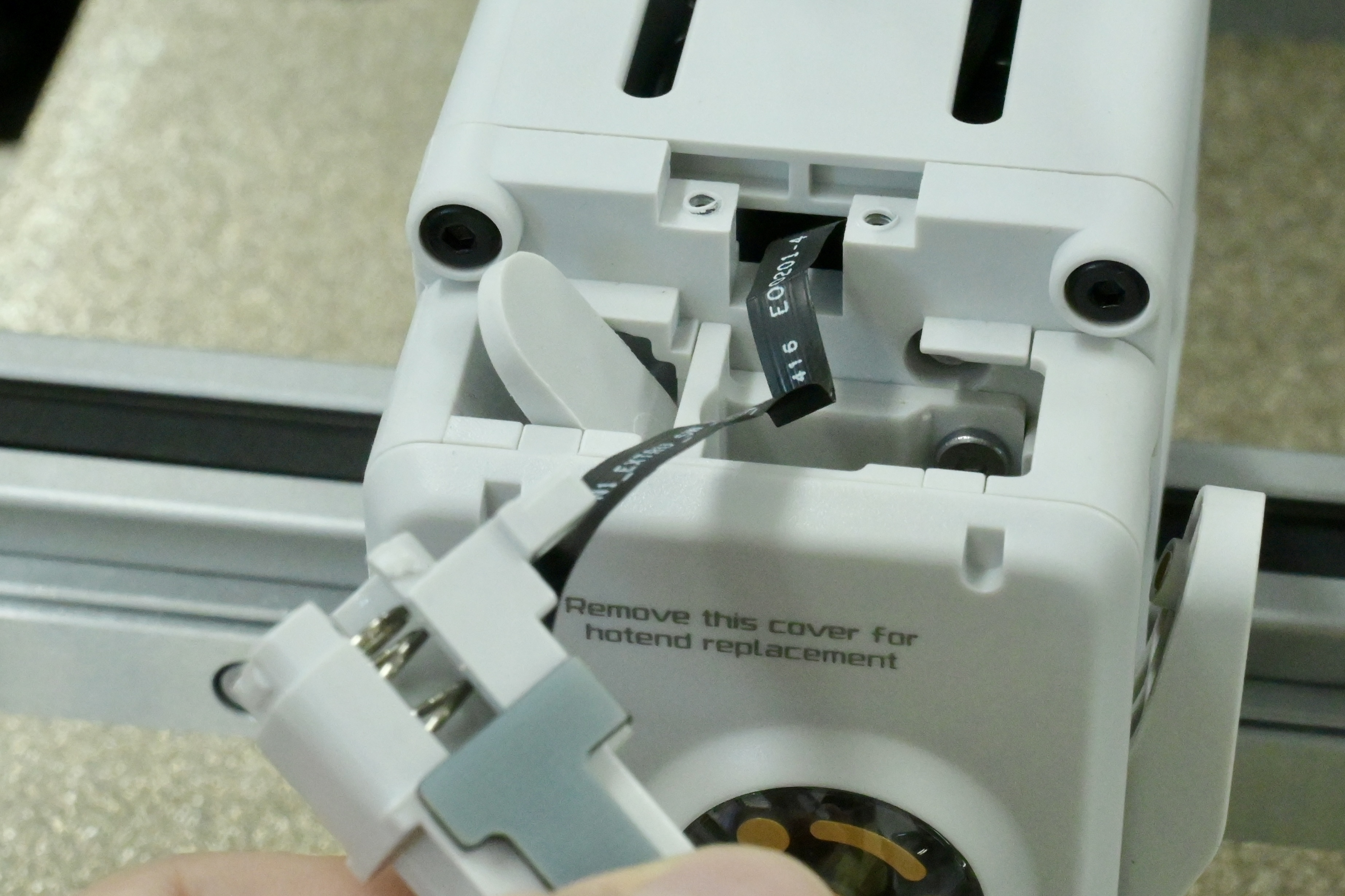 |
¶ Troubleshooting Guide
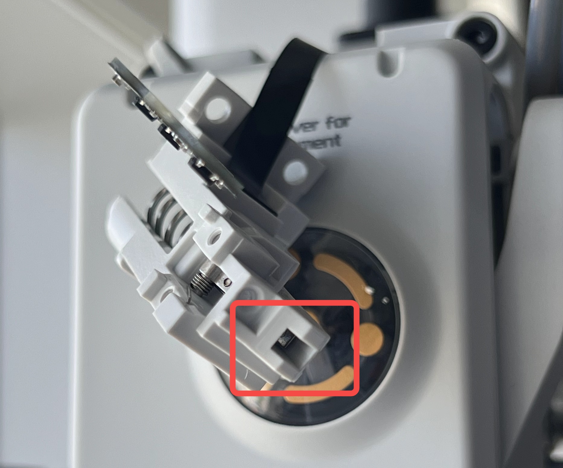
¶ Inspect the inside of the filament sensor
Check if there is any residual filaments stuck inside the filament sensor.
¶ Inspect the arm
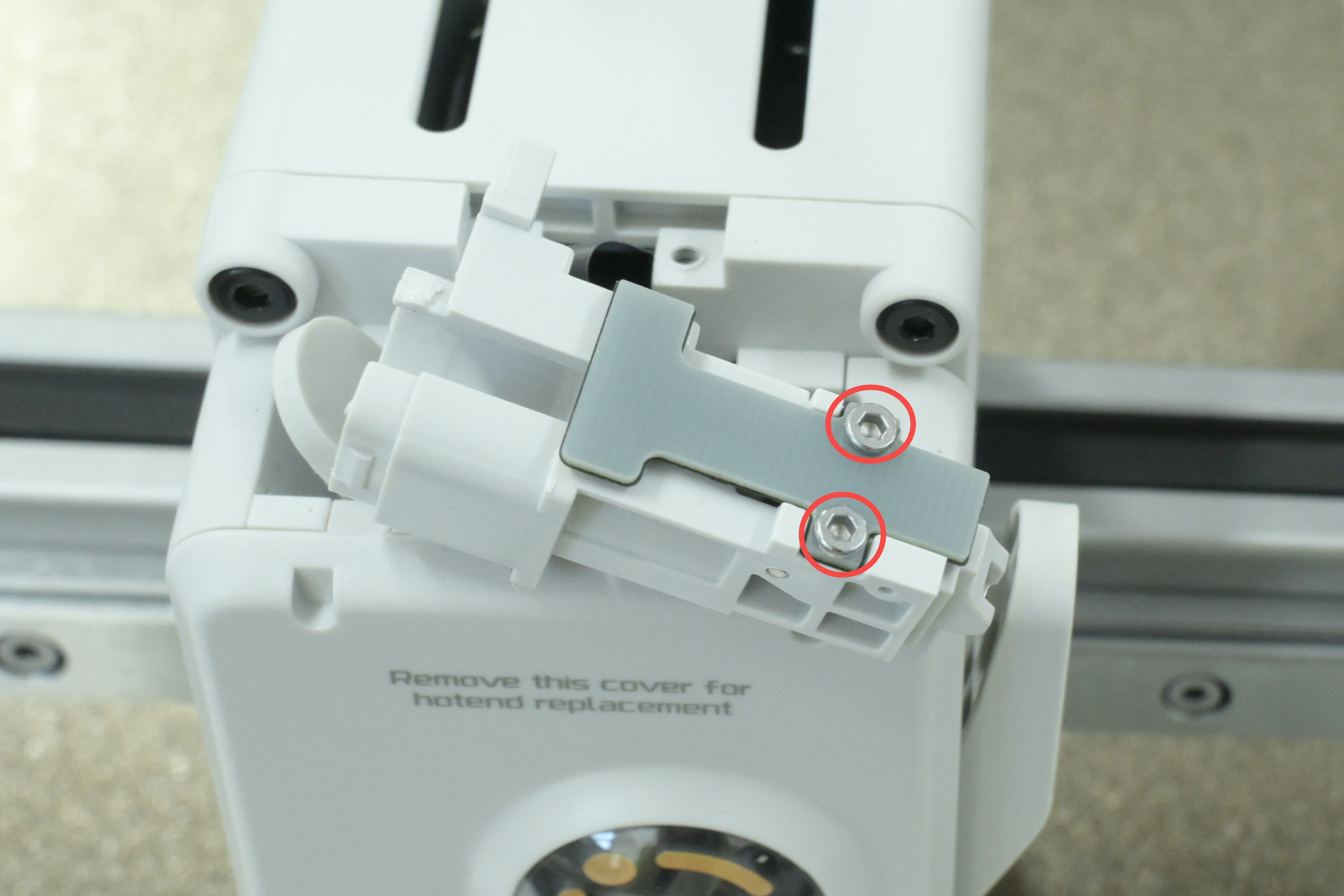
¶ Step 1: Remove the filament sensor
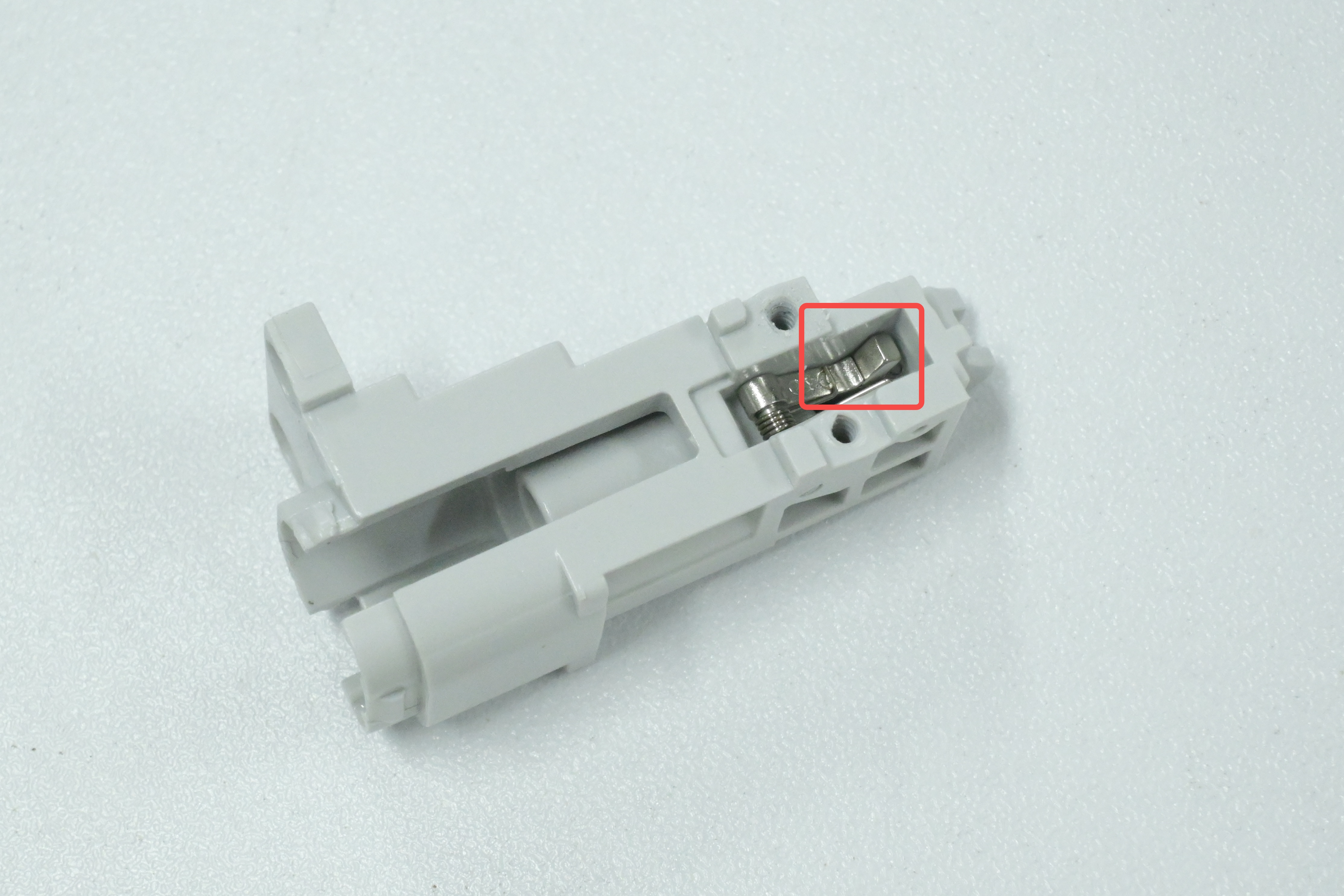
Remove the 2 screws on the filament sensor using an H1.5 Allen key.
¶ Step 2:Inspect the arm
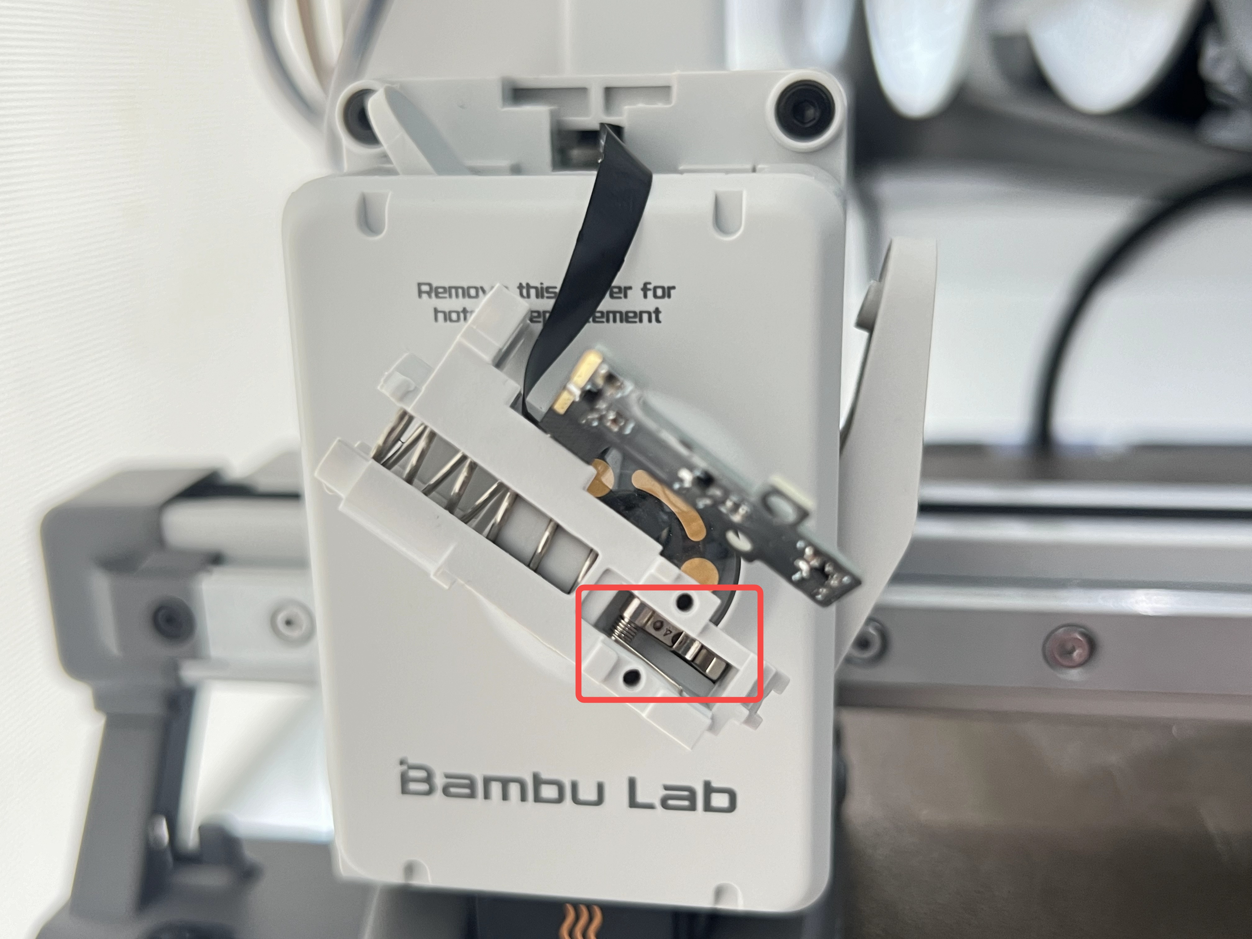
Insert a piece of filament and observe whether the arm operates normally and whether it returns to its original position automatically after the filament is removed.
 |
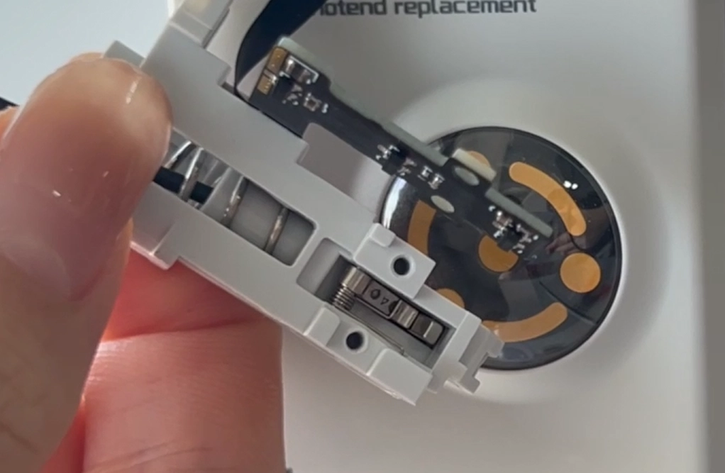 |
If the arm is stuck, move it left or right to return it to its original position.
¶ Assembly Guide
¶ Step 1: Install the filament sensor
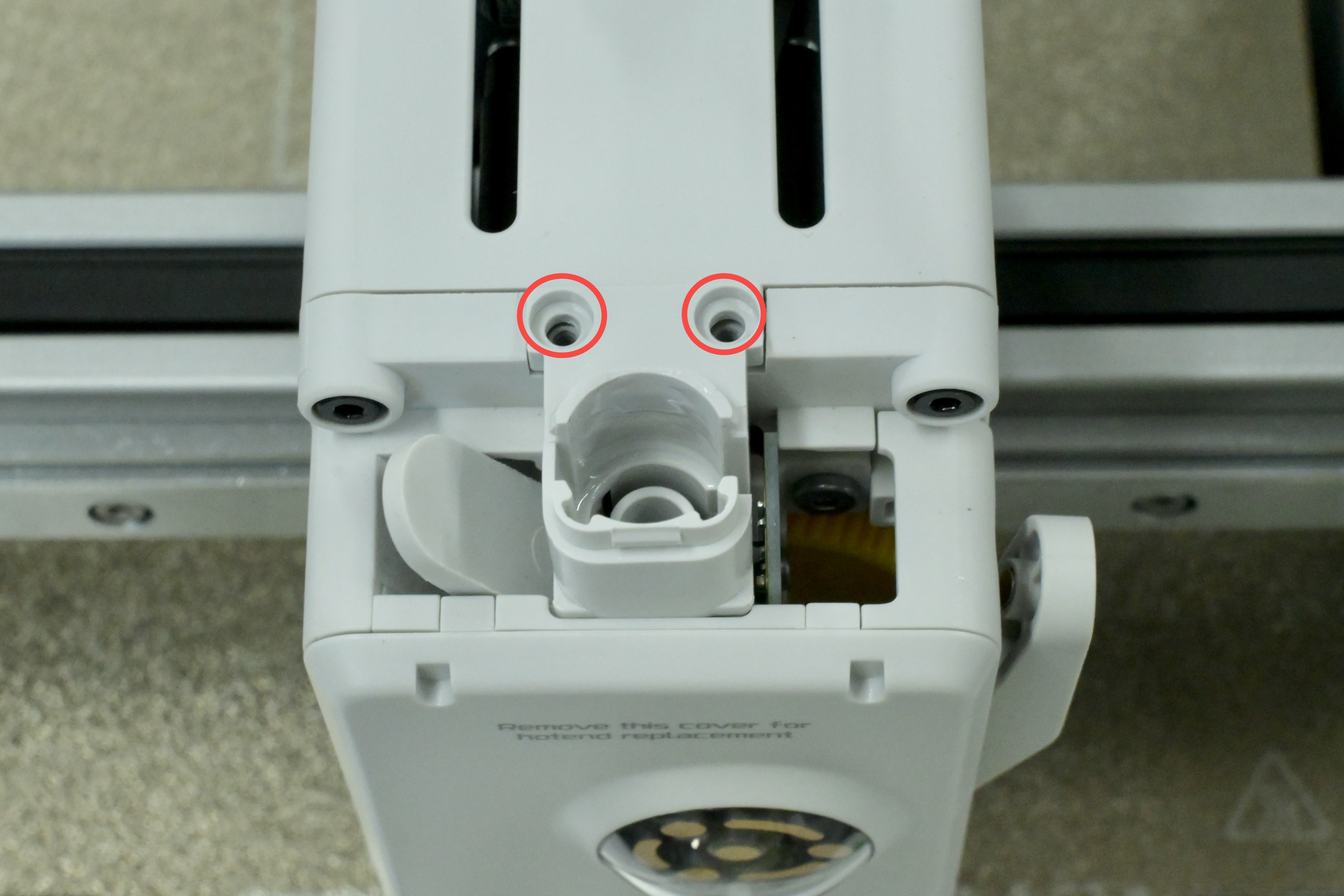
Use an H1.5 Allen key to install the 2 screws on the filament sensor.

¶ Step 2: Install the filament base
Put the filament base back and install the 2 screws on the top of the base with an H2.0 Allen key.
¶ Step 3: Install the filament hub
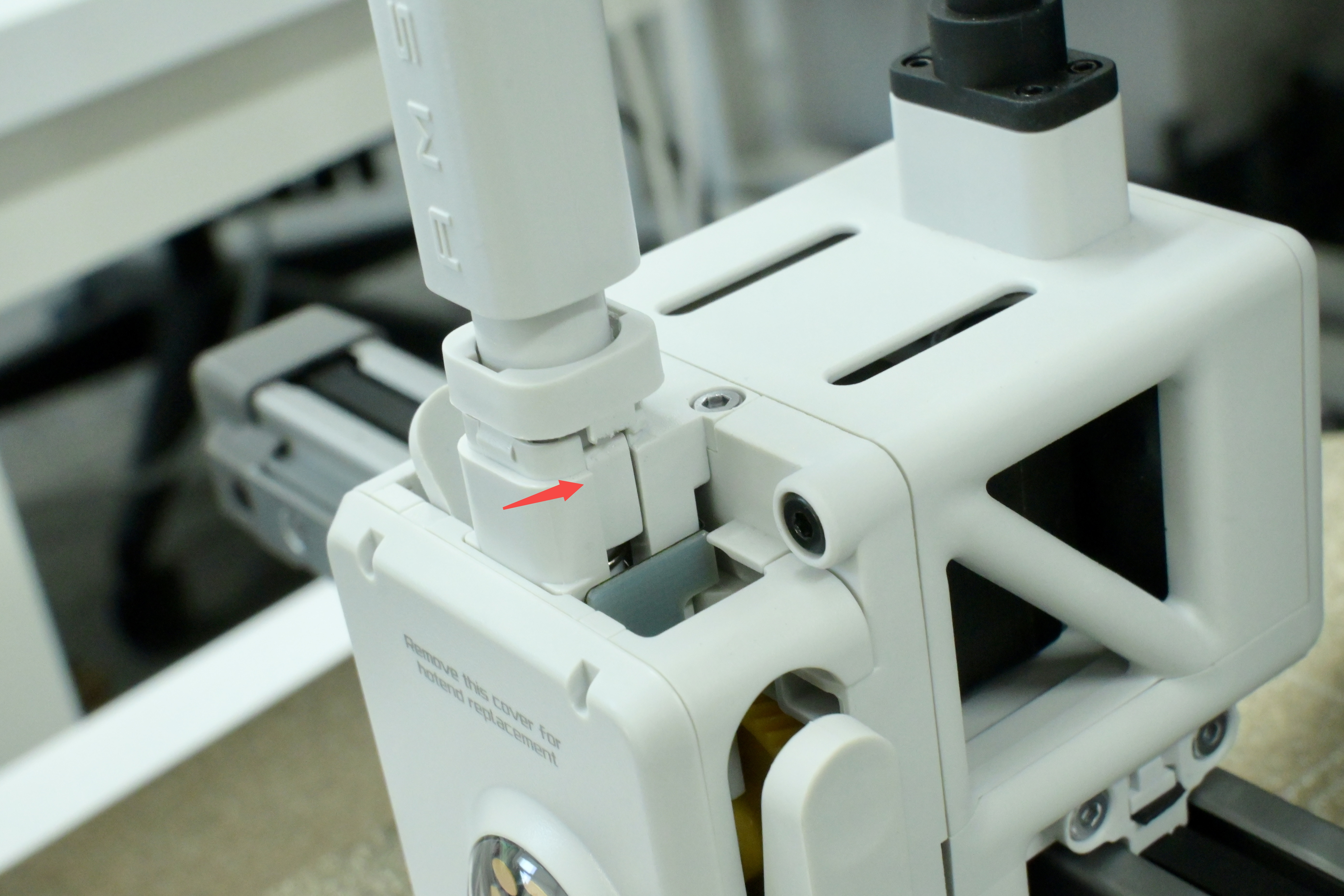
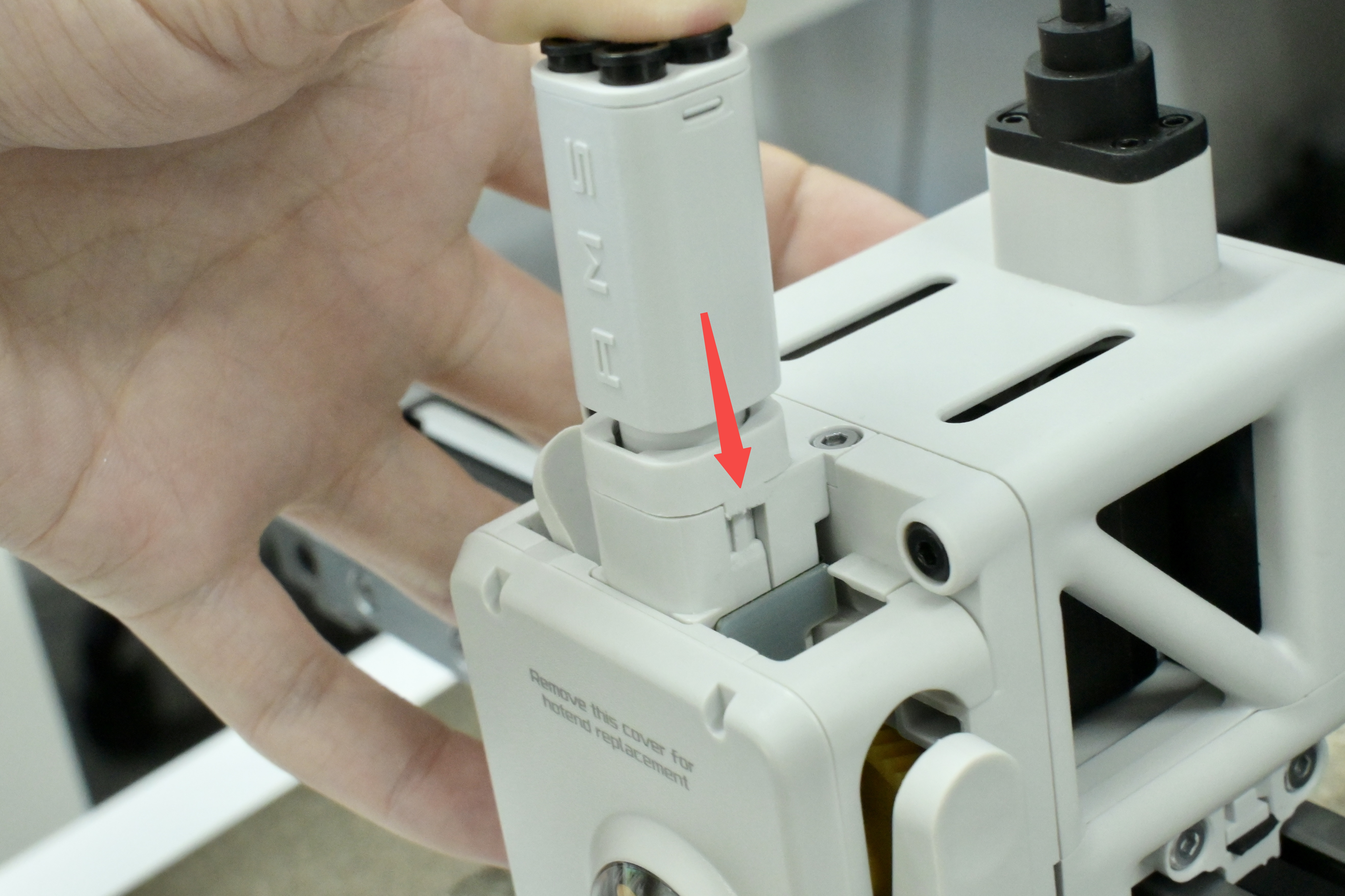
Install the Filament Hub onto the printer. Align the mounting buckles as shown in the figure below, then press down on the bottom bracket body to lock the filament hub.
 |
 |
¶ End Notes
We hope the detailed guide provided has been helpful and informative.
If this guide does not solve your problem, please submit a technical ticket, we will answer your questions and provide assistance.
If you have any suggestions or feedback on this Wiki, please leave a message in the comment area. Thank you for your support and attention!
