¶ Observation
The main control board cannot obtain the version number of the CTC (Chamber Temperature Control) module, which is generally due to a loose link of the CTC module or damage to the CTC module.
¶ Troubleshooting
¶ Safety Warning
IMPORTANT!
It's crucial to power off the printer before performing any maintenance work on the printer and its electronics, including tool head wires, because leaving the printer on while conducting such tasks can cause a short circuit, which can lead to additional electronic damage and safety hazards.
When you perform maintenane or troubleshooting on the printer, you may be required to disassemble some parts, including the hotend. This process can expose wires and electrical components that could potentially short circuit if they come into contact with each other or with other metal or electronic components while the printer is still on. This can damage the electronics of the printer and cause further damage.
Therefore, it's essential to switch off the printer and disconnect it from the power source before doing any maintenance work. This will prevent any short circuits or damage to the printer's electronics. By doing so, you can avoid potential damage to the printer's electronic components and ensure that the maintenance work is performed safely and effectively.
If you have any concerns or questions about following this guide, open a new ticket in our Support Page and we will do our best to respond promptly and provide you with the assistance you need.
Please follow the steps below to troubleshoot:
¶ Step 1. Restart the printer
¶ Step 2. Check if the CTC connector is loose, and reconnect it if necessary.
¶ Screws list
| Model | Position | Drawing | Model | Position | Drawing | ||
| Screw A | ST3*4.5 |
Rear panel (9PCS) |
 |
Screw B |
BT3*5
|
Rear panel, Air duct (4PCS/3PCS) |
 |
| Screw C | M3*4.5 |
Rear panel, Right panel (1PCS、15PCS) |
|
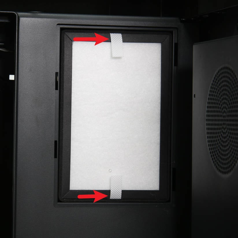
¶ 2.1 Remove the Activated Carbon Air Filter
Remove the glass cover plate, lower the heatbed to the bottom by pulling the Z-axis belt, and expose the entire filter cover, as shown in Figure 1-1-1, then uncover and remove the filter cover;
As shown in Figure 1-1-2, pull the strap of the filter with two hands to remove the Activated Carbon Air Filter.
|
|
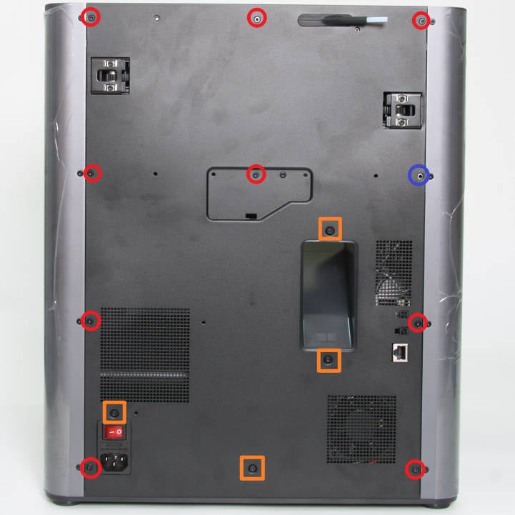
¶ 2.2 Remove the Rear Panel
Remove the glass cover plate, and then as shown in Figure 1-2-1, remove 9 screws A, 4 screws B, and 1 screw C with the H2.0 hex key;
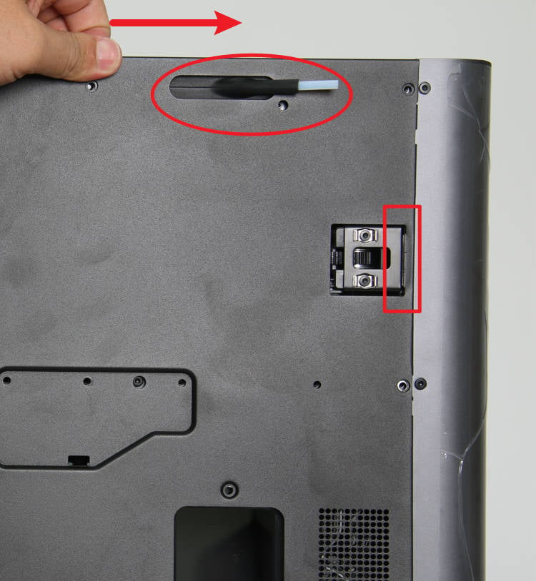
As shown in Figure 1-2-2, first push the rear panel to the right a little bit, and loosen the rear panel from the tensioner on the right side;
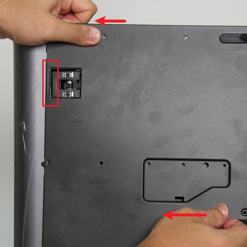
As shown in Figure 1-2-3, apply force to the left, release the rear panel from the left tensioner, and remove the rear panel.
|
|
|
¶ 2.3 Remove the Air Duct
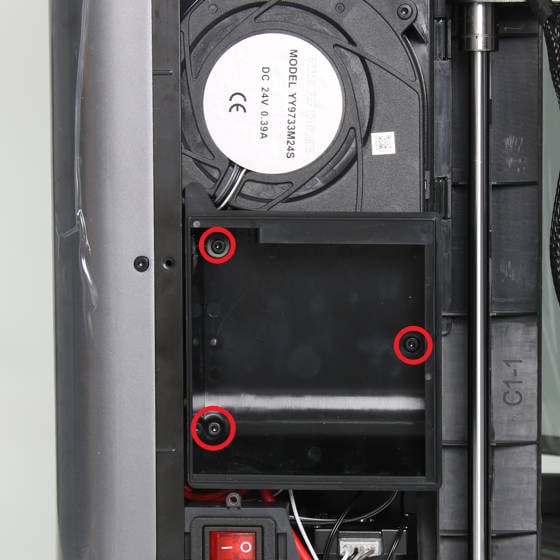
As shown in Figure 1-4-1, remove the 3 screws B with the H2.0 hex key and remove the air duct;
¶ 2.4 CTC Connector Loose Check
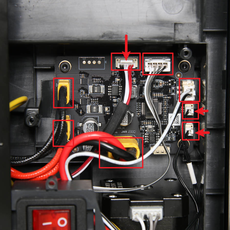
As shown in Figure 1-5-1, disconnect the 8 connecting cables from the heater control board. Note that the connector plugs indicated by the arrows have a buckle. When unplugging, you need to press the buckle to unlock;
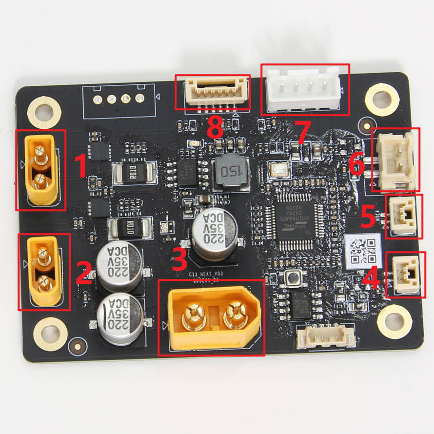
As shown in Figure 1-5-3, the numbered connectors are connected to the following objects:
1- Chamber Heater Unit(Black, GND)
2- Chamber Heater Unit(Red,24V)
3- Internal Power Supply (24V)
4- Network Interface and AMS Connection Board
5- Internal Power Supply NTC
6- Power Cooling Fan
7- Chamber Heater Unit FAN
8- Chamber Heater Unit NTC
|
|
¶ Step 3. Replace the CTC module
If the CTC module needs to be replaced, please refer to: Wiki | X1E Chamber Heater Unit Replacement
¶ Error message
HMS_0500-0300-0001-0023: The Chamber Temperature Control module is malfunctioning. Please restart the device.
¶ End Notes
We hope that the detailed guide we shared with you was helpful and informative.
We want to ensure that you can perform it safely and effectively. If you have any concerns or questions regarding the process described in this article, we encourage you to reach out to our friendly customer service team before starting the operation. Our team is always ready to help you and answer any questions you may have.
Click here to open a new ticket in our Support Page.
We will do our best to respond promptly and provide you with the assistance you need.