¶ Extruder Module
This article offers guidelines and precautions for disassembling and assembling the A1 series extruder module. The disassembly process, including component replacement, can also be found in this article for reference.
¶ Parts List
The following are the individual after-sales items that will be involved in this guide.
| No. | Name | Image | No. | Name | Image |
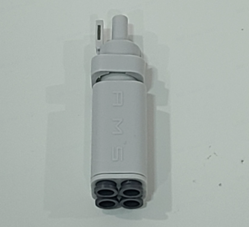
| 1 | Filament Hub |
 |
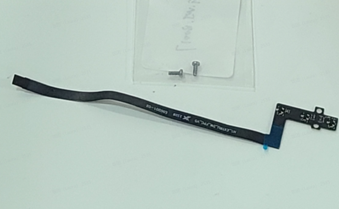
2 | Filament sensor for A1 series |
 |
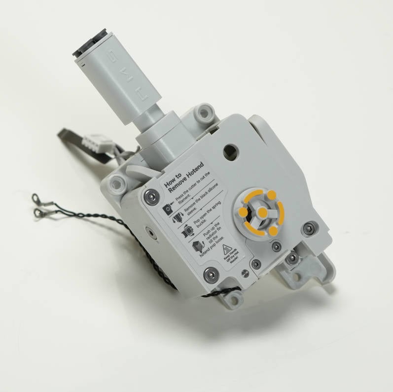
| 3 | Extruder Unit for A1 series |
 |
4 | Replacement filament cutter |
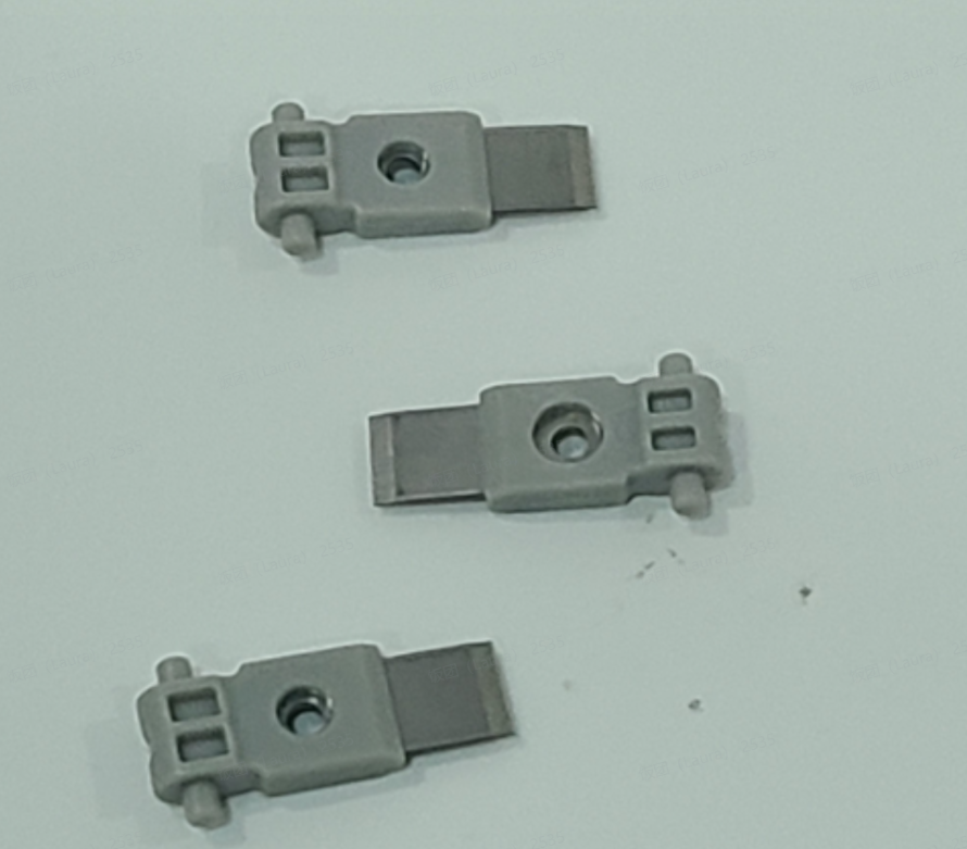 |
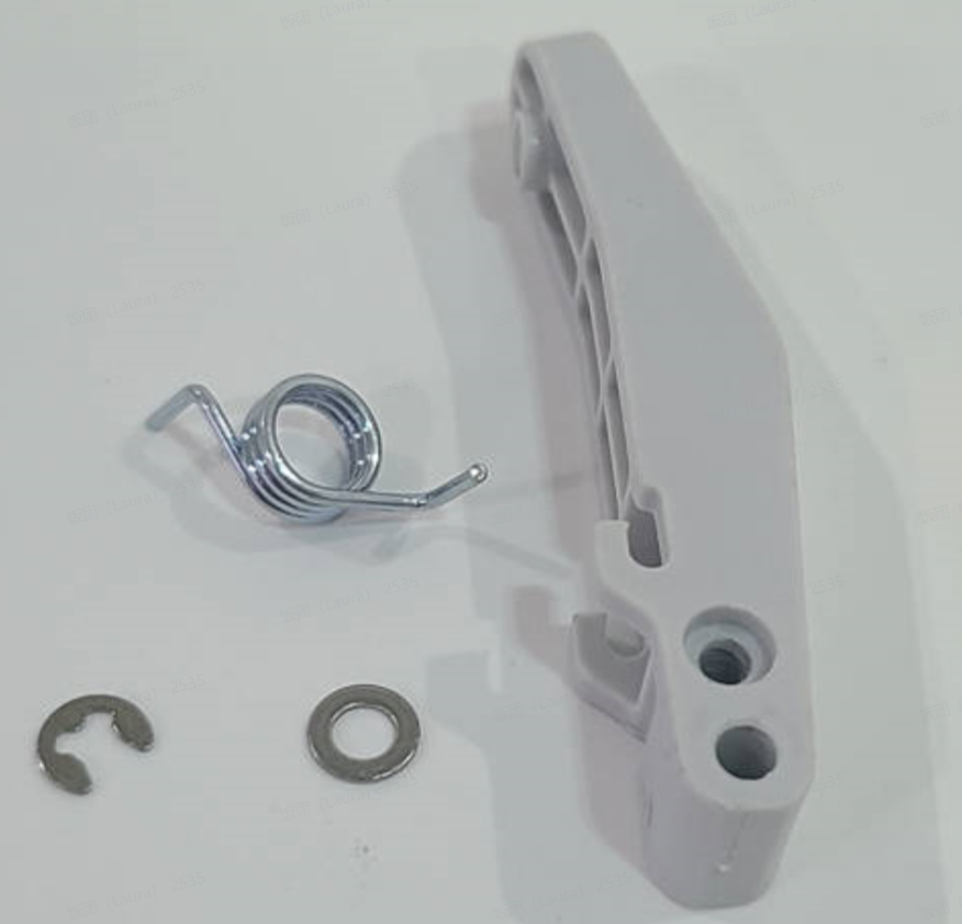
| 5 | Filament Cutter Lever |
 |
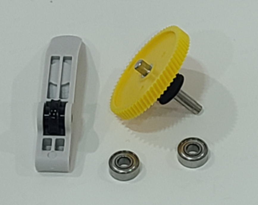
6 | Extruder Gear Assembly |
 |
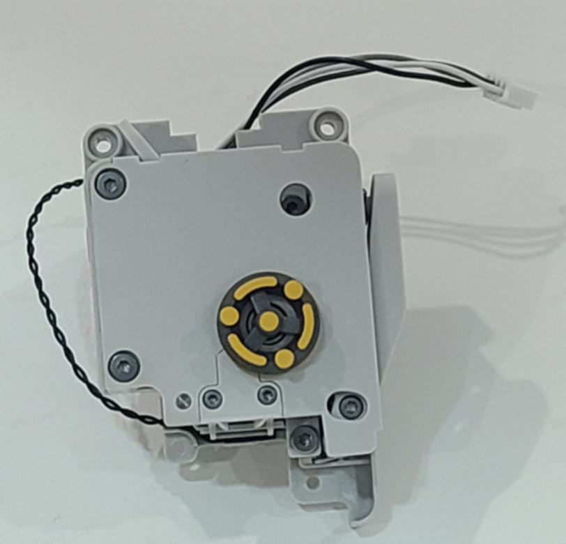
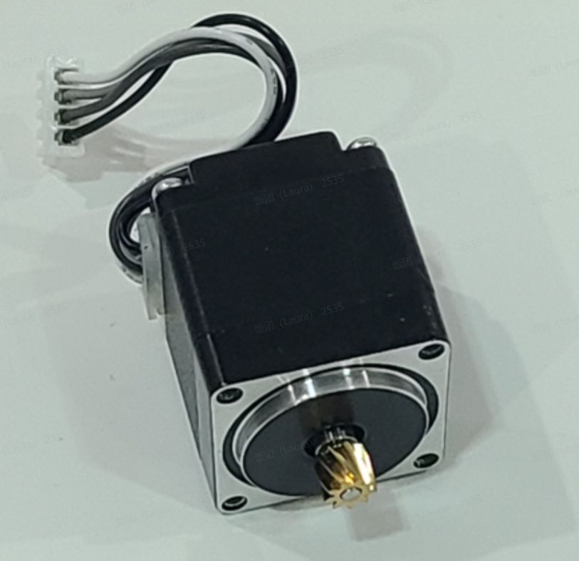
| 7 | A1 series Extruder Motor |
 |
¶ Module List
None
¶ Screw List
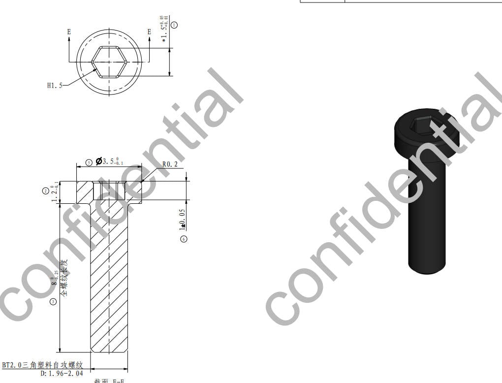
| Model | Location | Specifications/Drawings | Model | Location | Specifications/Drawings | ||
| Screw A | BT2*8 B00248 |
Filament Tension Block. (2PCS) |
 |
Screw B | BT2.6*5 B00204 |
Feeding Bracket (2PCS) |
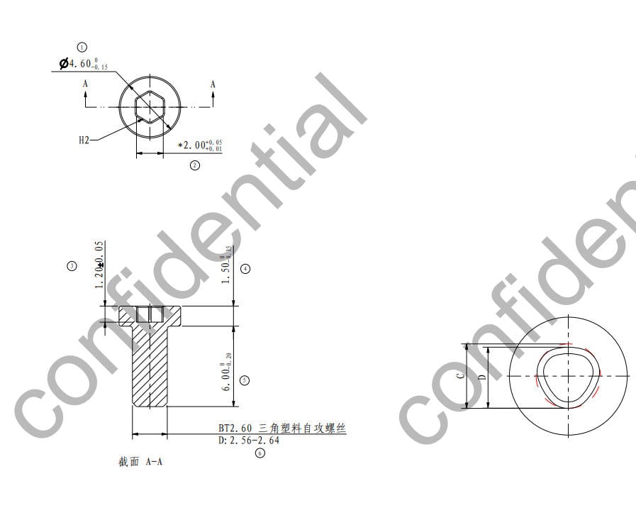 |
| Screw C | BT2*5 B0017 |
Filament Sensor (2PCS) |
 |
Screw D | BT2.6*14 B00205 |
Filament Cutter Lever (1PCS) |
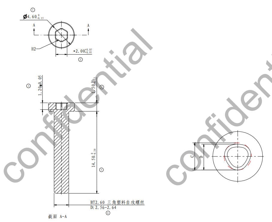 |
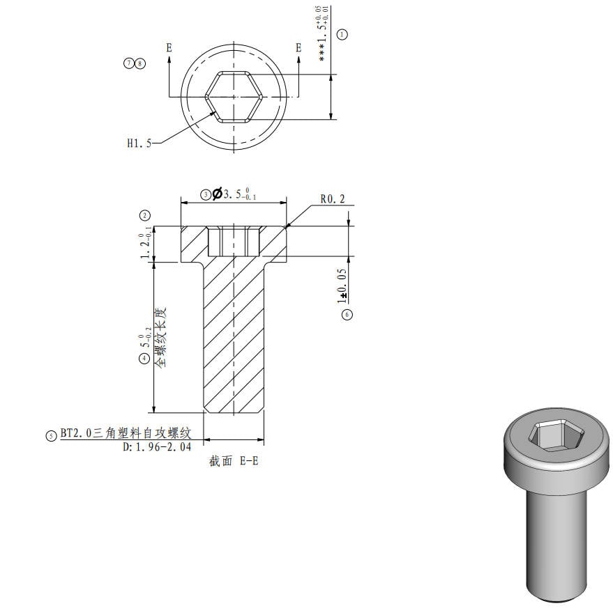
| Screw E | B00246 BT2.3*7 |
Extruder Front Cover (4PCS) |
 |
Screw F | M3*11 B00276 |
Extruder Driven Wheel (1PCS) |
 |
| Screw G | M2.5*5 B00202 |
Extruder Motor (4PCS) |
 |
¶ Tool list
H1.5/H2.0 hex key tool
Flat head tweezers
¶ Previous Operation
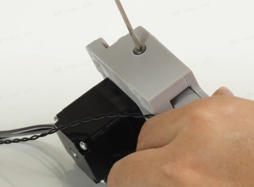
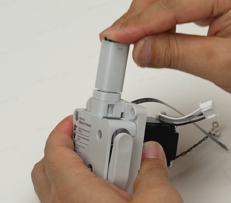
If necessary, please refer to the Replace the Toolhead-A1 Series to remove the extrusion module from the toolhead.
¶ Safety Warning
IMPORTANT!
It's crucial to power off the printer before conducting any maintenance work, including work on the printer's electronics and tool head wires. Performing tasks with the printer on can result in a short circuit, leading to electronic damage and safety hazards.
During maintenance or troubleshooting, you may need to disassemble parts, including the hotend. This exposes wires and electrical components that could short circuit if they contact each other, other metal, or electronic components while the printer is still on. This can result in damage to the printer's electronics and additional issues.
Therefore, it's crucial to turn off the printer and disconnect it from the power source before conducting any maintenance. This prevents short circuits or damage to the printer's electronics, ensuring safe and effective maintenance. For any concerns or questions about following this guide, open a new ticket in our Support Page and we will do our best to respond promptly and provide the assistance you need.
¶ Video Guide
¶ Disassembly
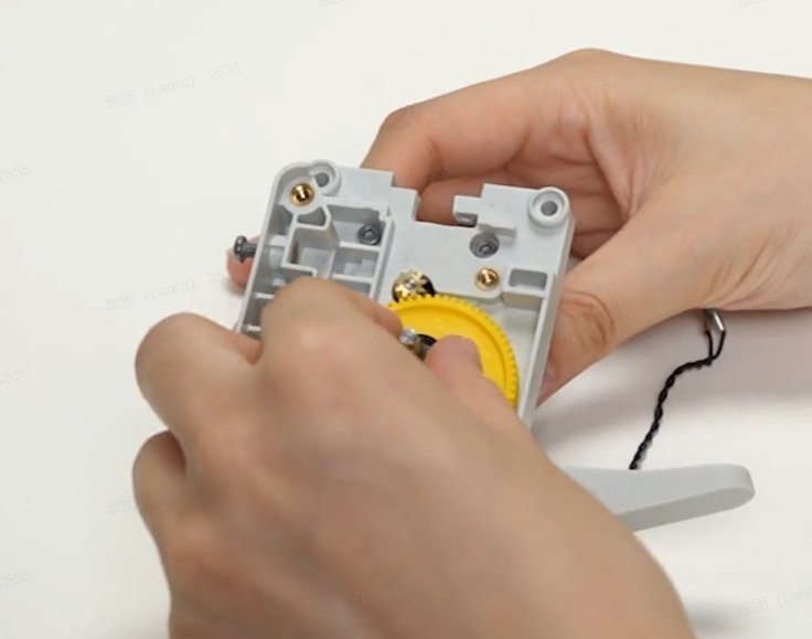
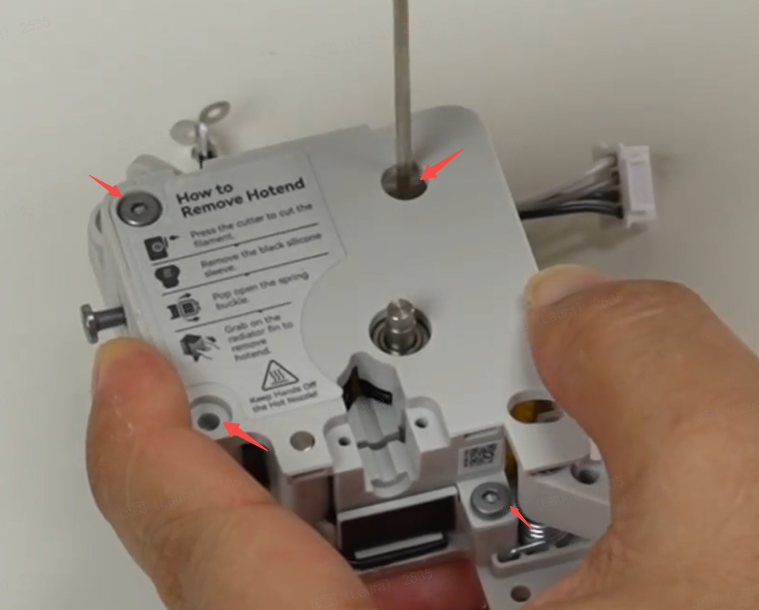
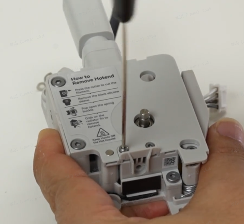
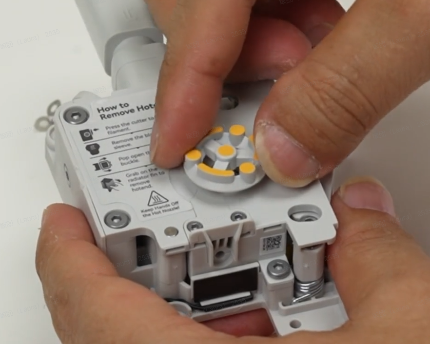
¶ Step 1: Remove the Filament Press Block
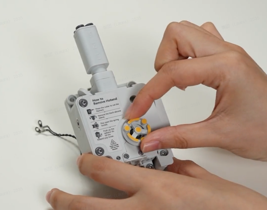
Remove the rotating wheel by using an H1.5 hex key wrench to unscrew 2 screws A. Then, take off the pressure block.
 |
 |
 |
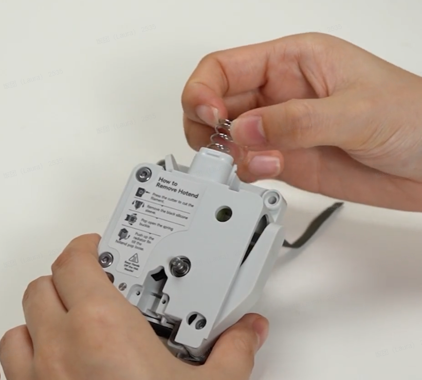
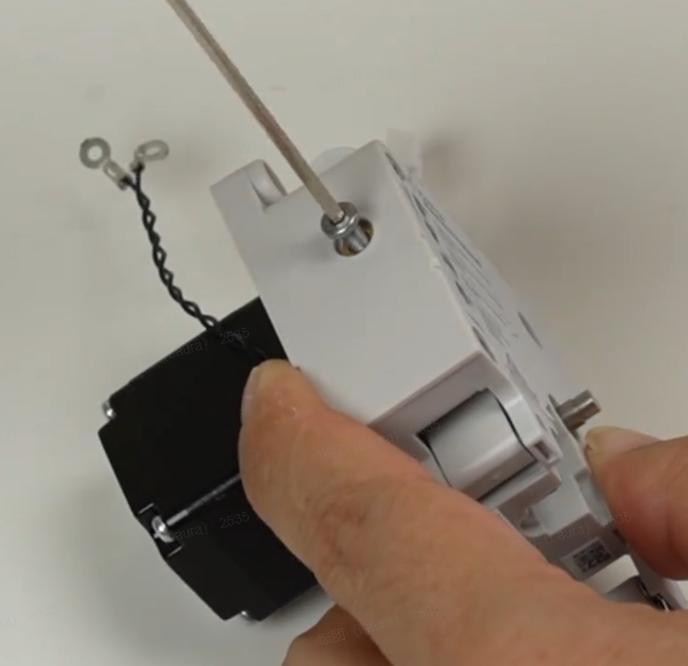
¶ Step 2: Remove the Filament Hub Assembly
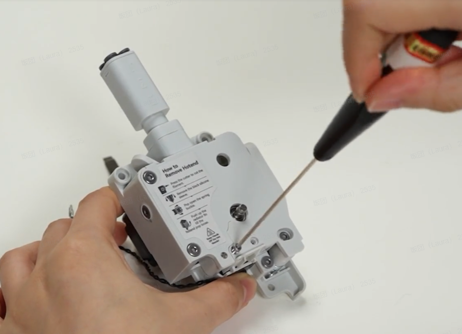
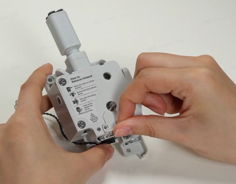
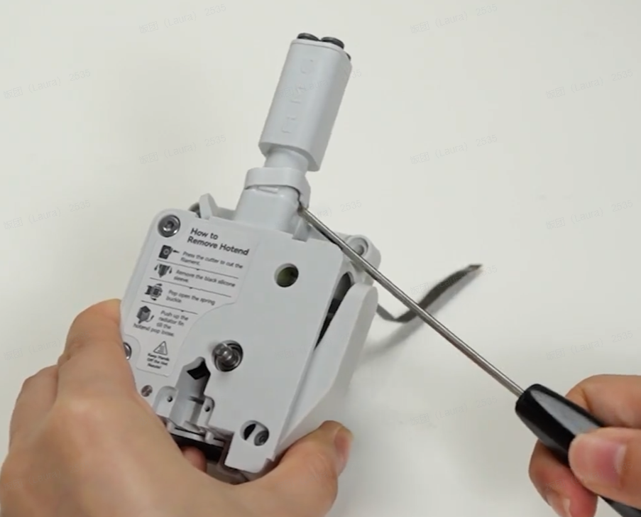
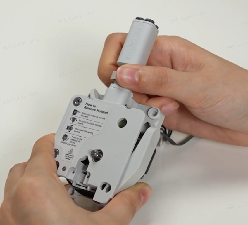
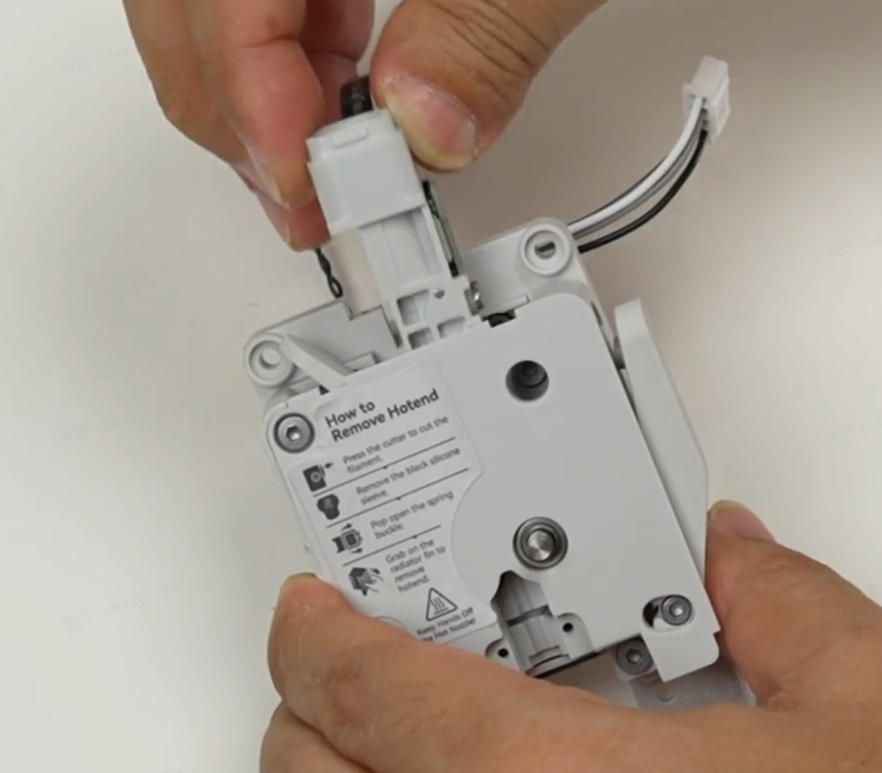
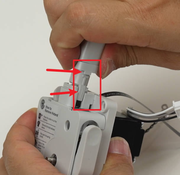
Use a wrench to delicately pry off the Filament Hub Cap. Then, remove the Filament Hub Assembly along with the corresponding spring.
 |
 |
 |
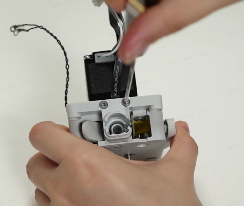
¶ Step 3:Remove the Filament Sensor
Use an H2.0 hex key wrench to unscrew 2 screws B and remove the Feeding Bracket.
 |
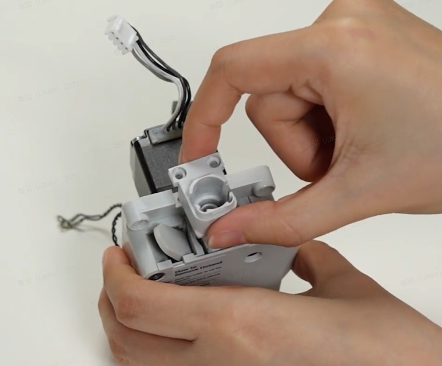 |
Use an H1.5 hex key wrench to unscrew 2 screws C and remove the Filament Sensor.
 |
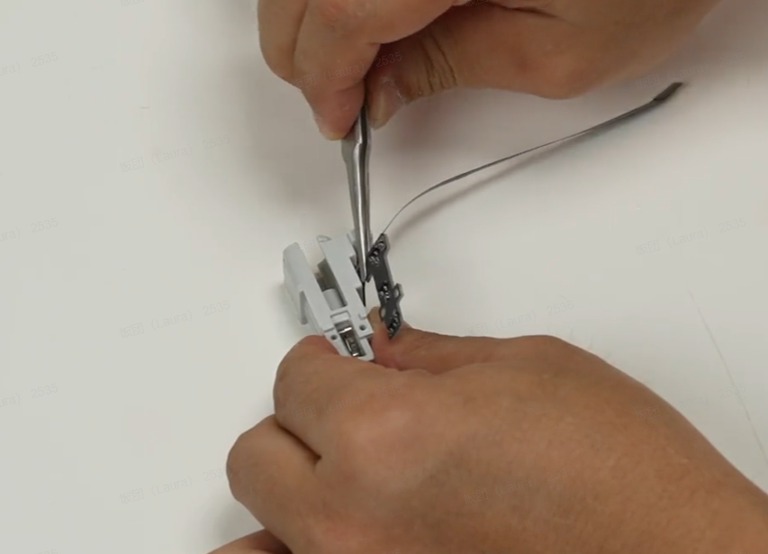 |
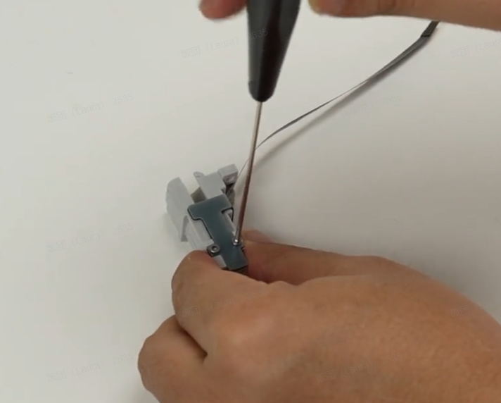
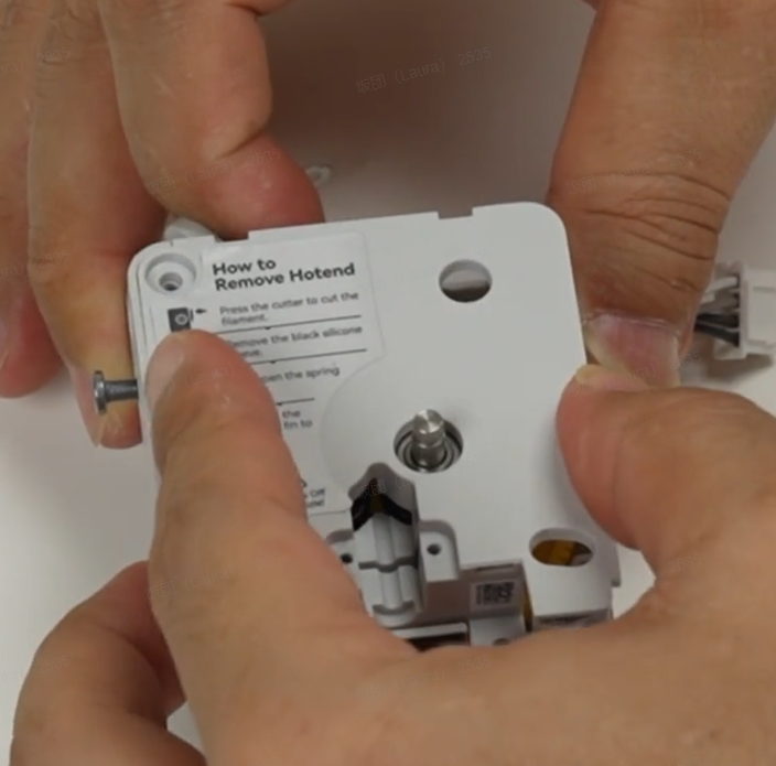
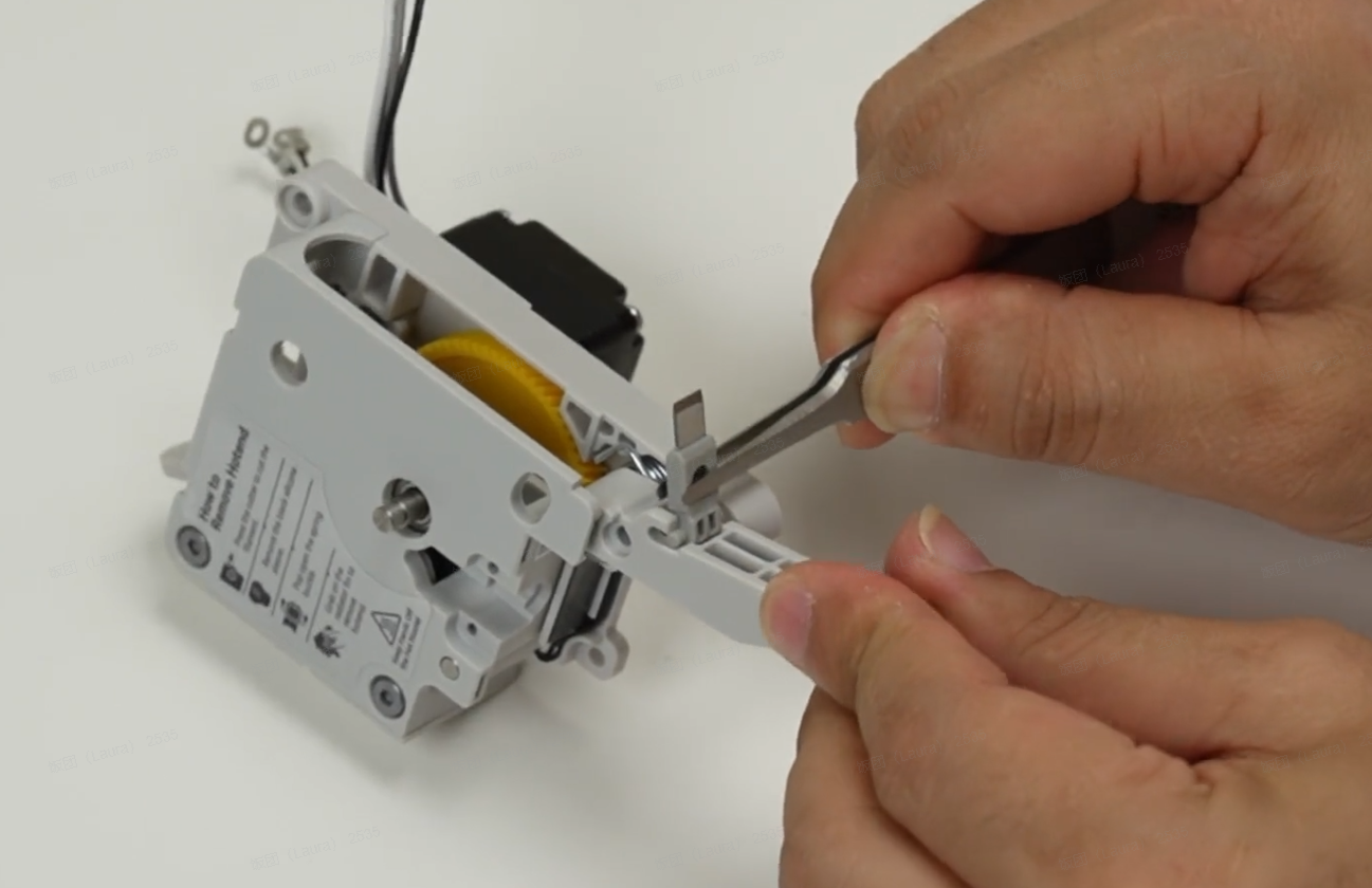
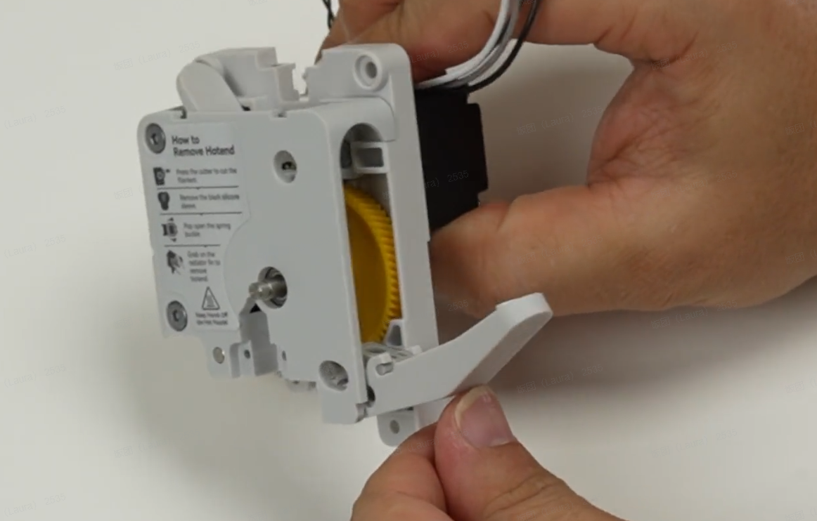
¶ Step 4: Remove the Replacement filament cutter
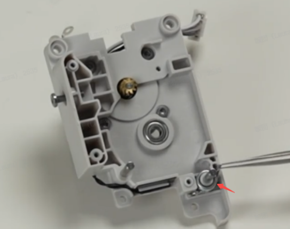
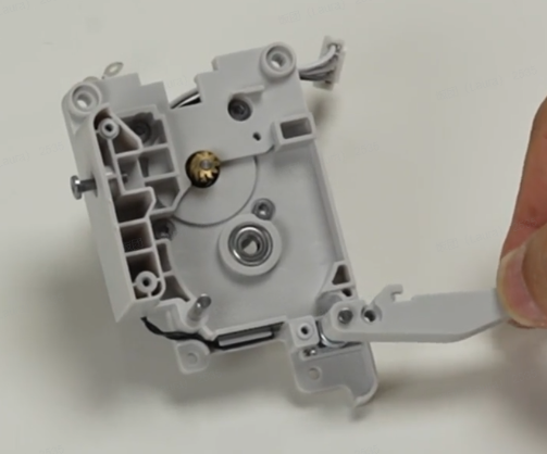
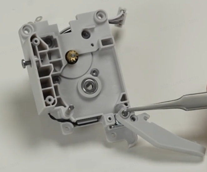
Use an H2.0 hex key wrench to unscrew one screw D, release the Filament Cutter Lever, and remove the filament cutter.
 |
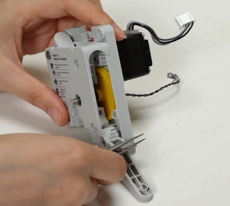 |
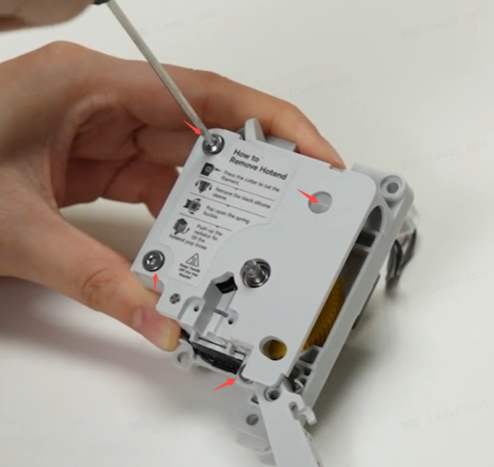
¶ Step 5: Remove the Extruder Gear Assembly.
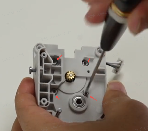
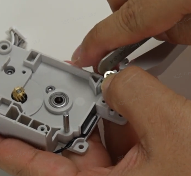
Use an H2.0 hex key wrench to unscrew 4 screws E, loosen one screw F, and remove the Extruder Front Cover.
 |
 |
 |
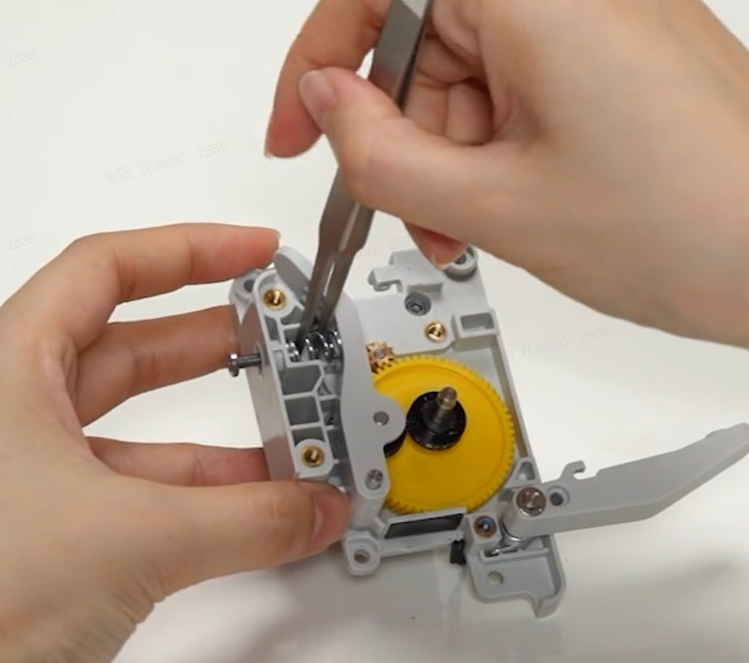
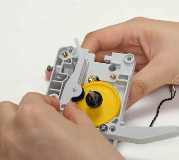
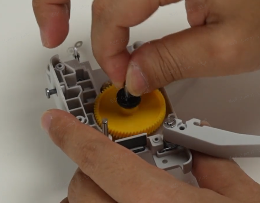
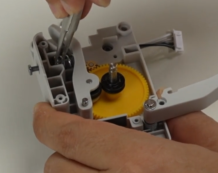
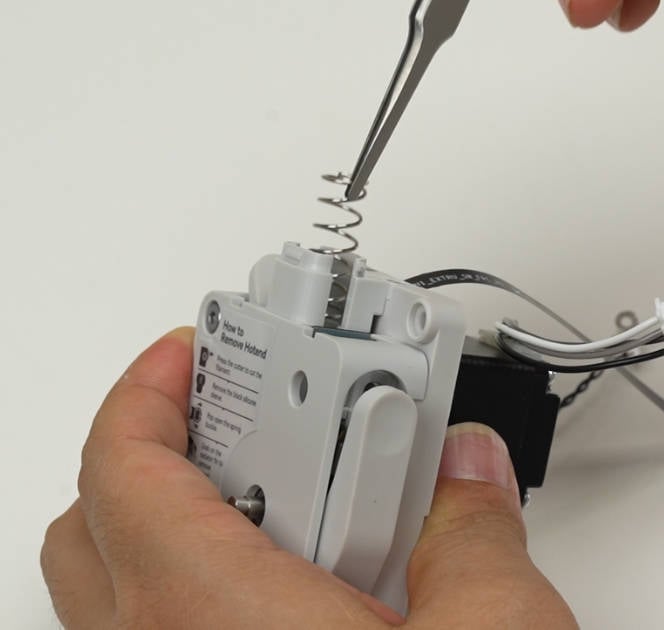
Use tweezers to remove the extrusion spring and the metal cap, and then take out the Extruder Gear Assembly.
 |
 |
 |
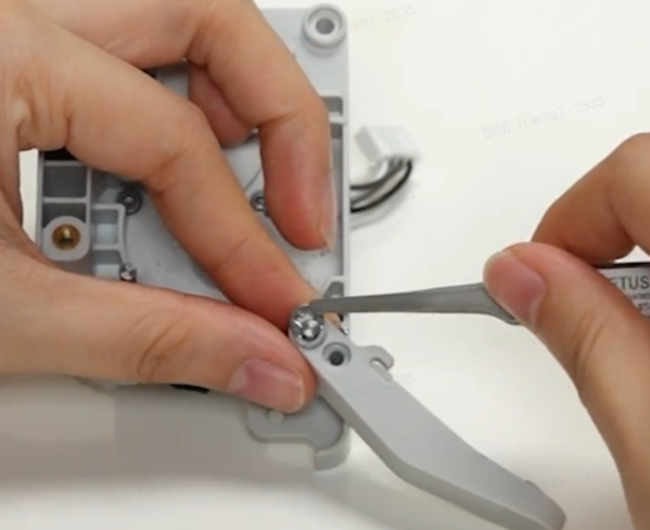
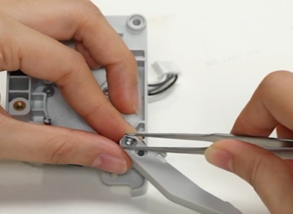
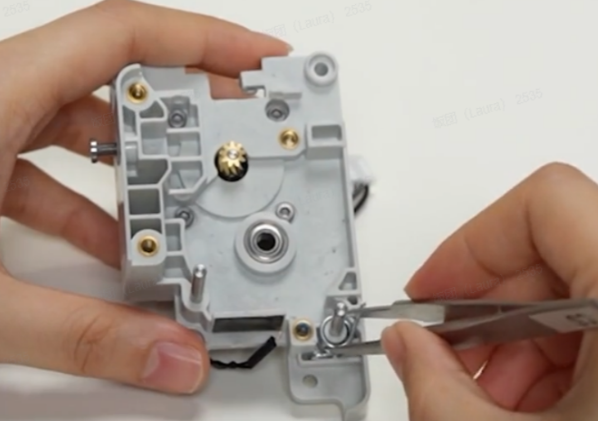
¶ Step 6: Remove the Filament Cutter Lever
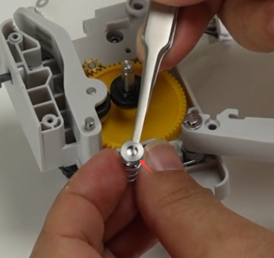
Use tweezers to remove the E-type retaining clip. While doing so, hold the retaining clip firmly to prevent it from springing off. Then, take off the washer, lever, and spring.
 |
 |
 |
 |
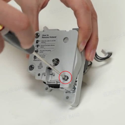
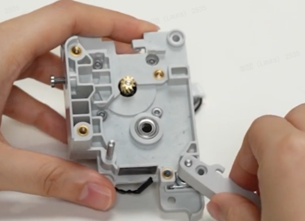
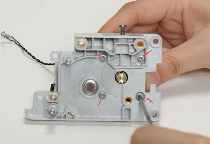
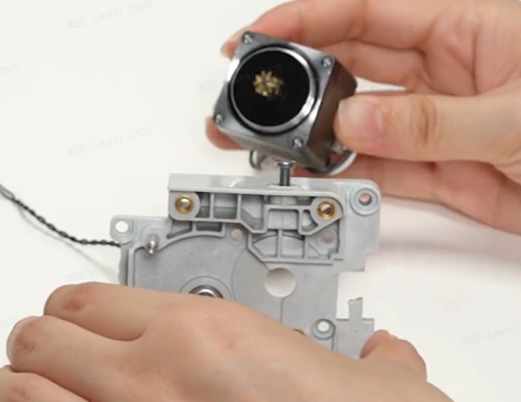
¶ Step 7: Remove the Extruder Motor
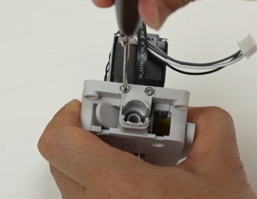
Use an H2.0 hex key wrench to unscrew 4 screws G and remove the Extruder Motor.
 |
 |
¶ Assembly Guide
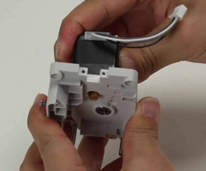
¶ Step 1: Install the Extruder Motor
Install the Extruder Motor onto the Extruder Rear Cover, ensuring the orientation of the motor cables. Use an H2.0 hex key wrench to tighten 4 screws G and secure the Extruder Motor.
 |
 |
¶ Step 2:Install the Filament Cutter Lever
Install the spring and handle onto the handle pivot. Place the washer on top, and then install the E-type retaining clip. Use tweezers to press the retaining clip and secure it in place.
 |
 |
 |
 |
¶ Step 3: Install the Extruder Gear Assembly
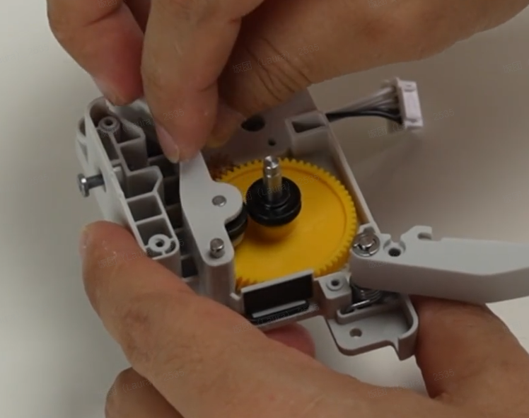
Install the extruder drive gear and idler gear onto their respective shafts.
 |
 |
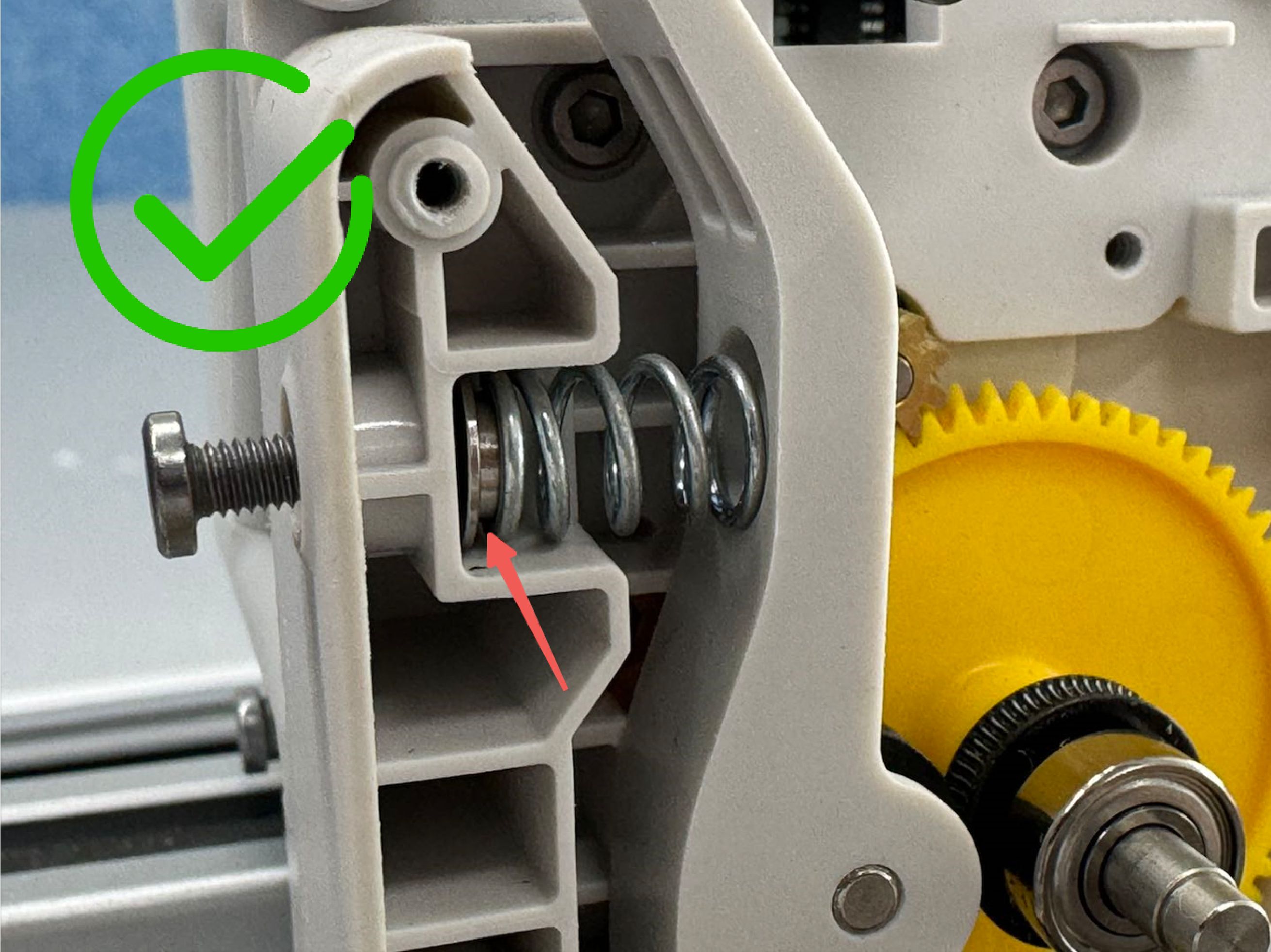
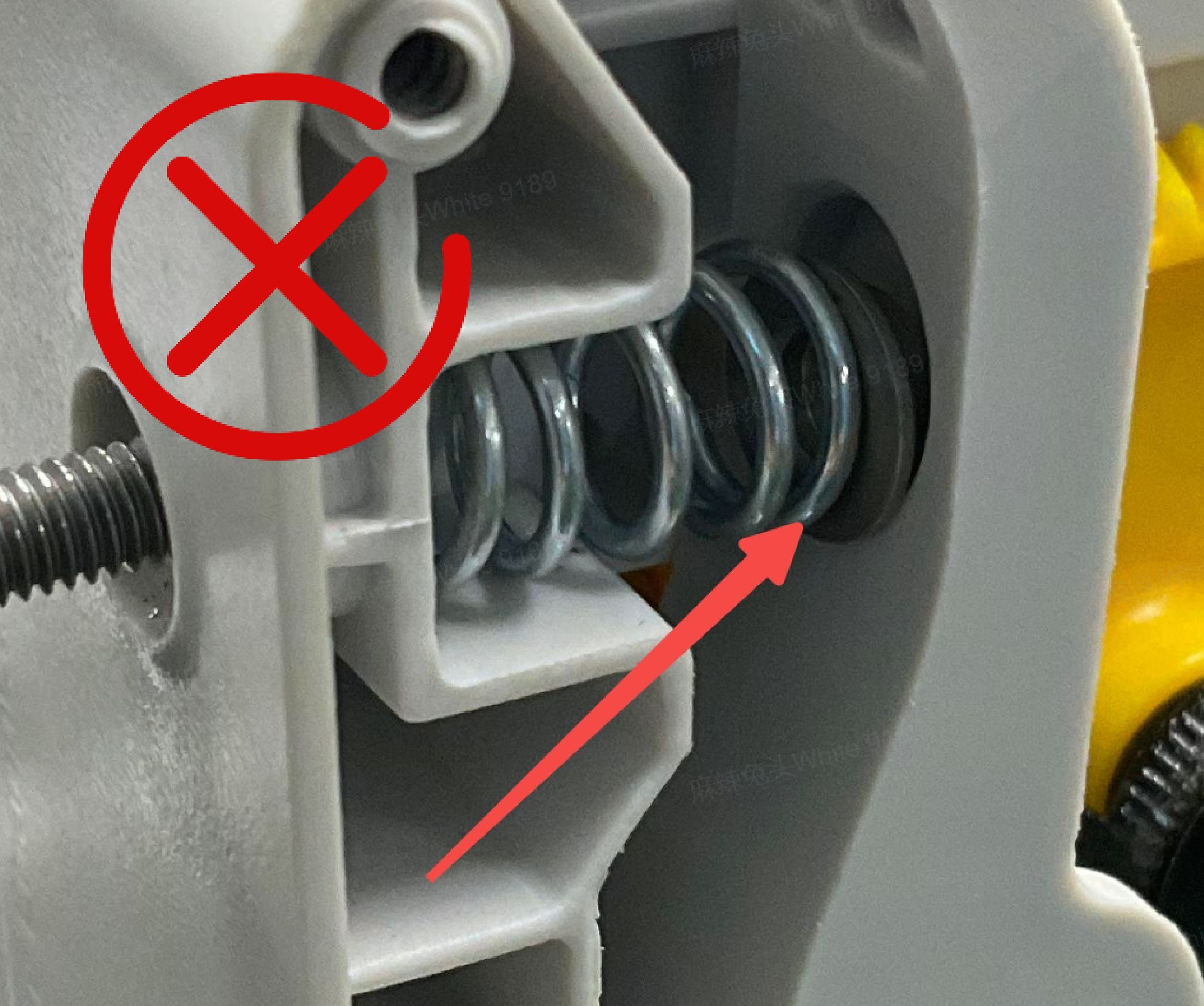
Assemble the spring and end cap together in the correct position and direction (see the images below for the correct and wrong examples), and carefully place them in the corresponding position of the driven wheel bracket using tweezers. Do not tighten the screw on the side for the moment.
Then, close the extruder front cover.
Important!
Please make sure to install the spring and end cap correctly. Otherwise, the gear will not be able to grip on the filament, causing print failure.
 |
 |
 |
|
|
Use an H2.0 hex key wrench to tighten 4 screws E, and then tighten screw F.
 |
 |
¶ Step 4: Install the Replacement Filament Cutter
Install the Replacement Filament Cutter onto the lever. Lift the lever and slide the cutter into place along the blade groove. Secure the lever by tightening one screw D.
 |
 |
 |
¶ Step 5: Install the Filament sensor
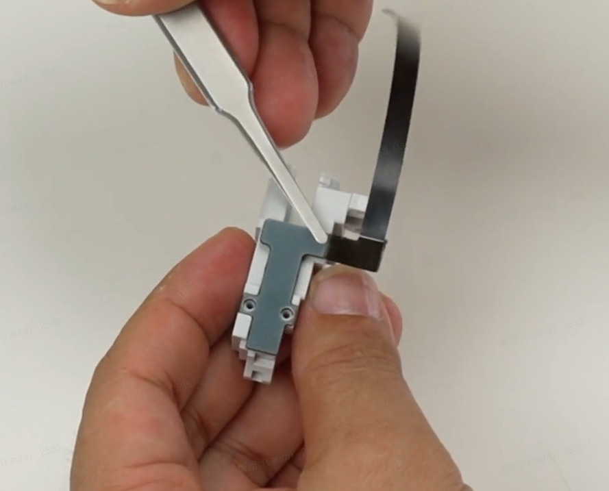
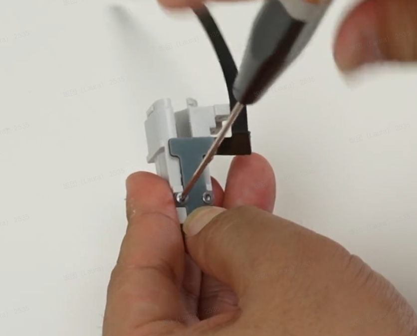
Install the Filament Sensor onto the Filament Feeding Bracket, tighten 2 screws, and then attach the ribbon cable.
 |
 |
 |
Install the Filament Hub base onto the extruder, and secure it by tightening 2 screws.
 |
 |
¶ Step 6: Install the Filament Hub Assembly.
Insert the spring into the Filament Hub base, and thread the cover onto the filament hub.
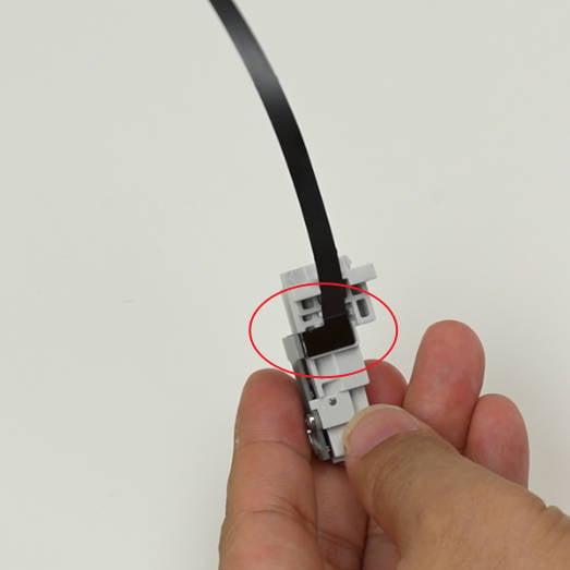
Verify the installation orientation as shown in the diagram below, and then attach the Filament Hub to the base.
Apply slight pressure to connect the Filament Hub with the base, and press to check for any looseness.
 |
 |
 |
¶ Step 7: Install the Filament Press Block.
Install the Filament Press Block, tighten 2 screws A, and then install the rotating wheel.
 |
 |
 |
¶ To verify completion/success
- Check and confirm that the Filament Cutter Lever operates smoothly.
- Press the Filament Hub Assembly to confirm its smooth operation.
¶ Calibration
Not required
¶ End Notes
We hope the detailed guide provided has been helpful and informative.
To ensure a safe and effective execution, if you have any concerns or questions about the process described in this article, we recommend submitting a Technical ticket regarding your issue. Please include a picture or video illustrating the problem, as well as any additional information related to your inquiry.