In this guide, we will show how to replace the Part Cooling Fan on the A1.
¶ When to use?
This guide is intended for use if there is a problem with the Part Cooling Fan
Common issues that may indicate the need for replacement of the A1 Part Cooling Fan include:
- The Part Cooling Fan has been damaged by wrapped in plastic due to a print failure
- The Part Cooling Fan is generating noise during operation
- Recommended by Bambu Lab Technical Support
¶ Tools and materials needed
-
H2.0 Allen key
-
H1.5 Allen key
-
20 minutes of your time
¶ Safety Warning
IMPORTANT!
It's crucial to power off the printer before conducting any maintenance work, including work on the printer's electronics and tool head wires. Performing tasks with the printer on can result in a short circuit, leading to electronic damage and safety hazards.
During maintenance or troubleshooting, you may need to disassemble parts, including the hotend. This exposes wires and electrical components that could short circuit if they contact each other, other metal, or electronic components while the printer is still on. This can result in damage to the printer's electronics and additional issues.
Therefore, it's crucial to turn off the printer and disconnect it from the power source before conducting any maintenance. This prevents short circuits or damage to the printer's electronics, ensuring safe and effective maintenance. For any concerns or questions about following this guide, open a new ticket in our Support Page and we will do our best to respond promptly and provide the assistance you need.
¶ Remove the Old Part Cooling Fan
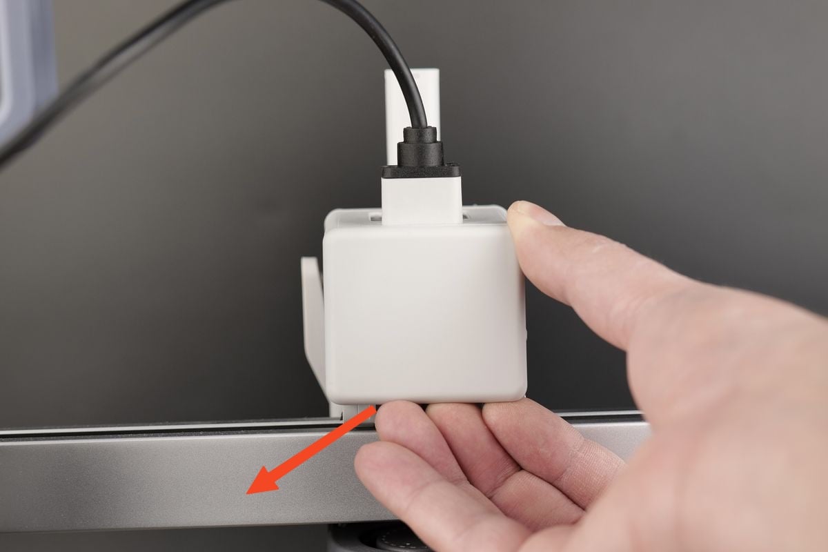
¶ 1. Remove the toolhead rear housing
We start by removing the toolhead rear housing.
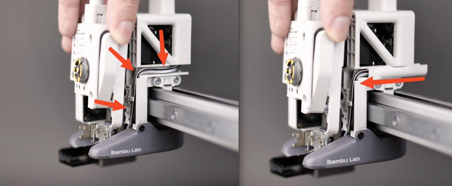
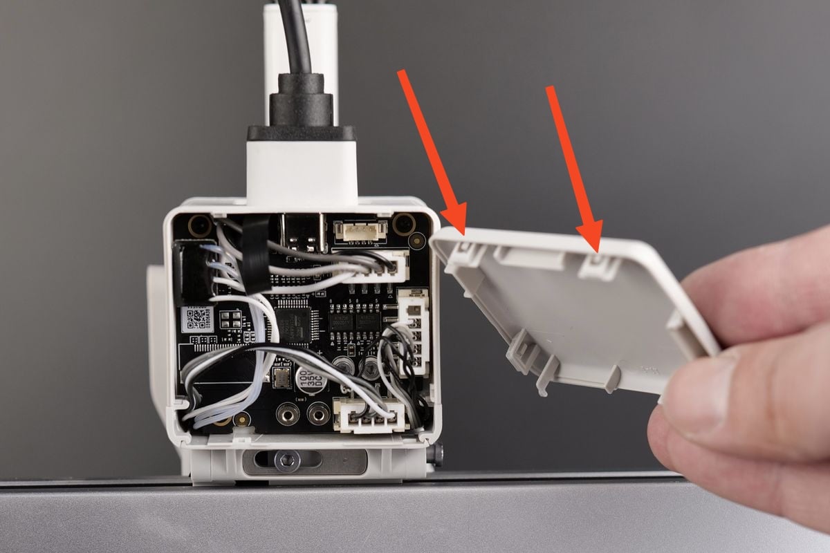
Carefully pry open the toolhead rear housing by pulling on the bottom section as shown below.
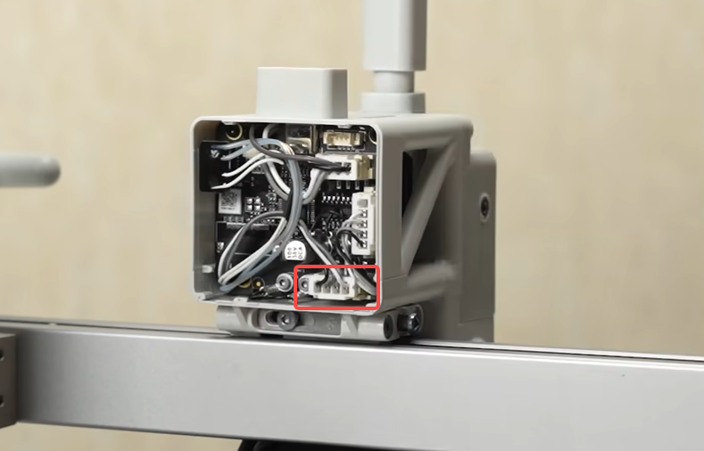
¶ 2. Disconnect the cable
Remove the part cooling fan cable attached to the TH Board.
Carefully pull it out by the connector, and avoid pulling the cable from the connector.
We recommend using a flat tool to gently pry them out to avoid any potential damage.
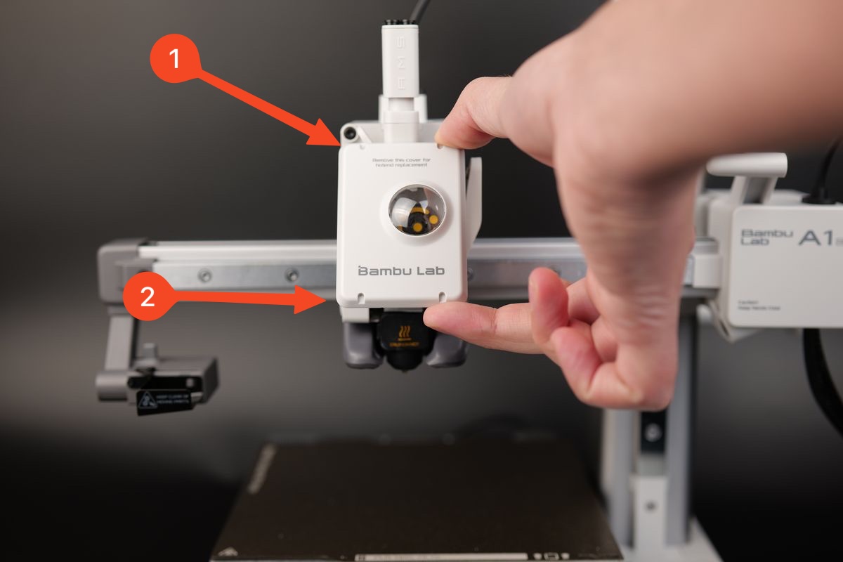
¶ 3. Remove the toolhead front cover
Grab the base of the front cover and gently pull towards you.
The clips holding the cover in place will be released, allowing you to remove the front cover

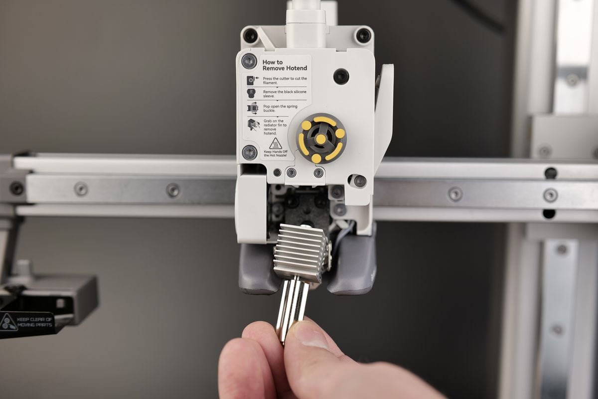
¶ 4. Remove the hotend
Remove the silicone sock for hotend by gently pulling it towards you, then remove the hotend.
All the steps are labeled on the extruder sticker.
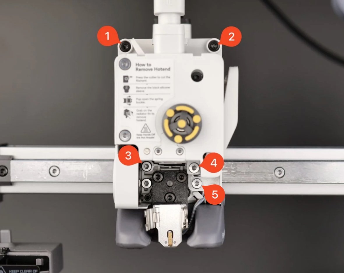
¶ 5. Remove the extruder screws
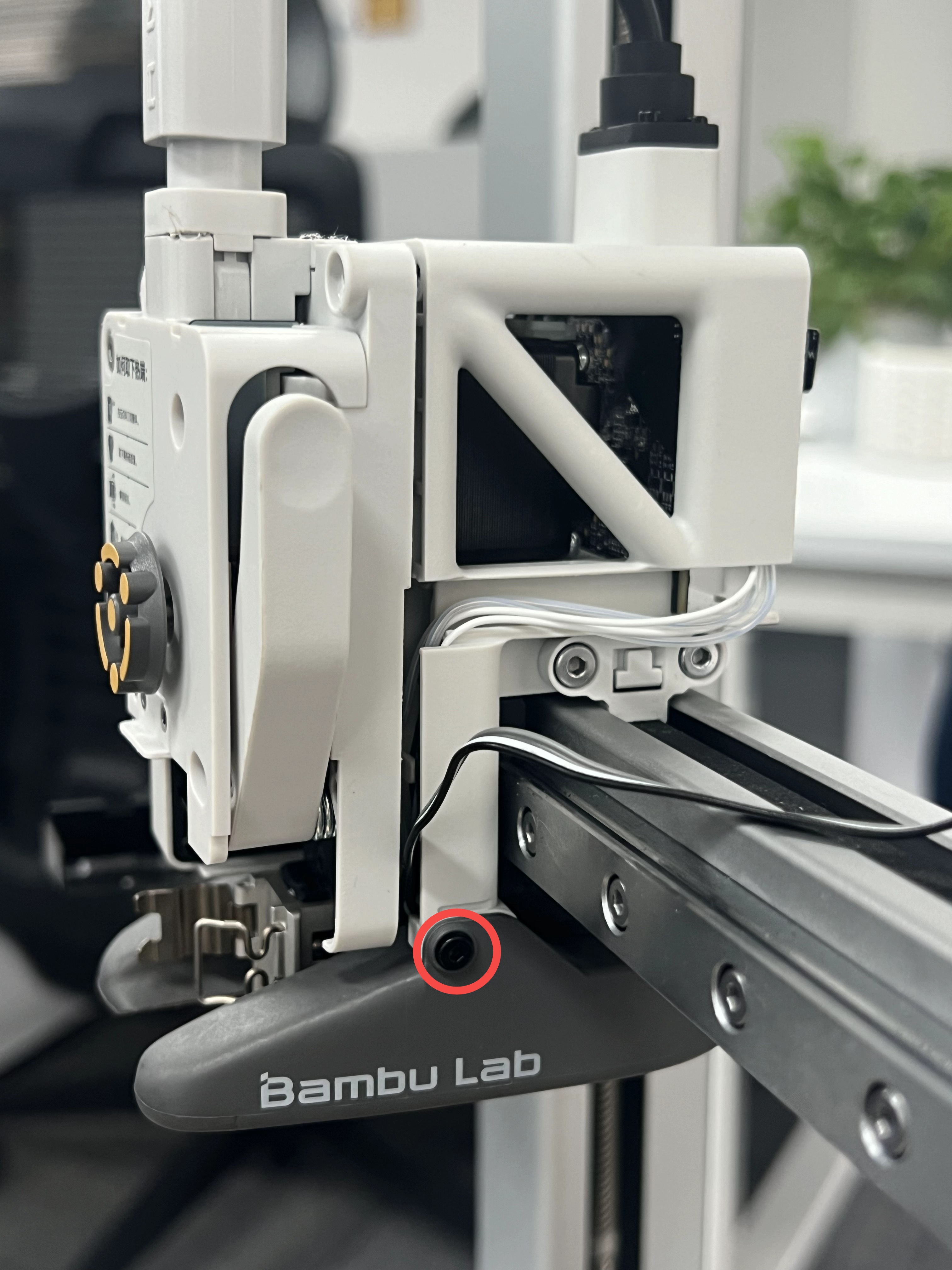
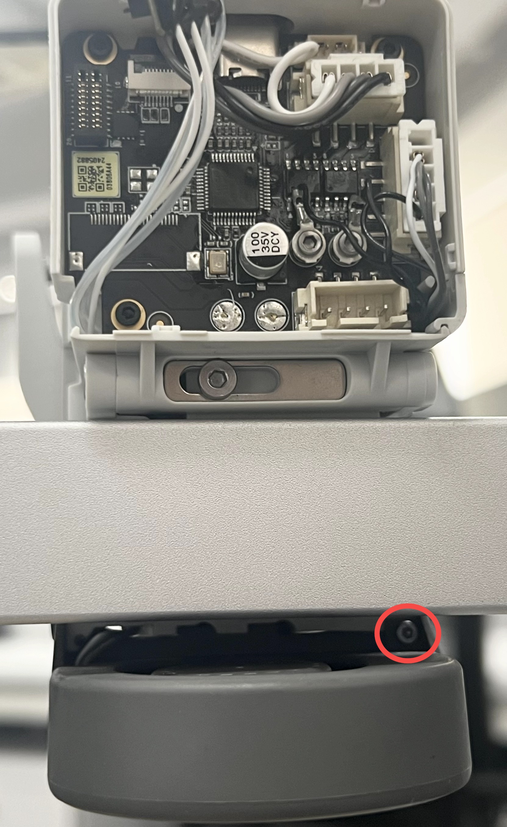
Remove the screws as shown in the picture, and gently pull the extruder forward a little. Be careful when pulling it out, as you will need to carefully disconnect the filament sensor ribbon cable.
¶ 6. Remove the part cooling fan cable
Push the right cable cover backward and remove it, then remove the part cooling fan cable from the cable channel.
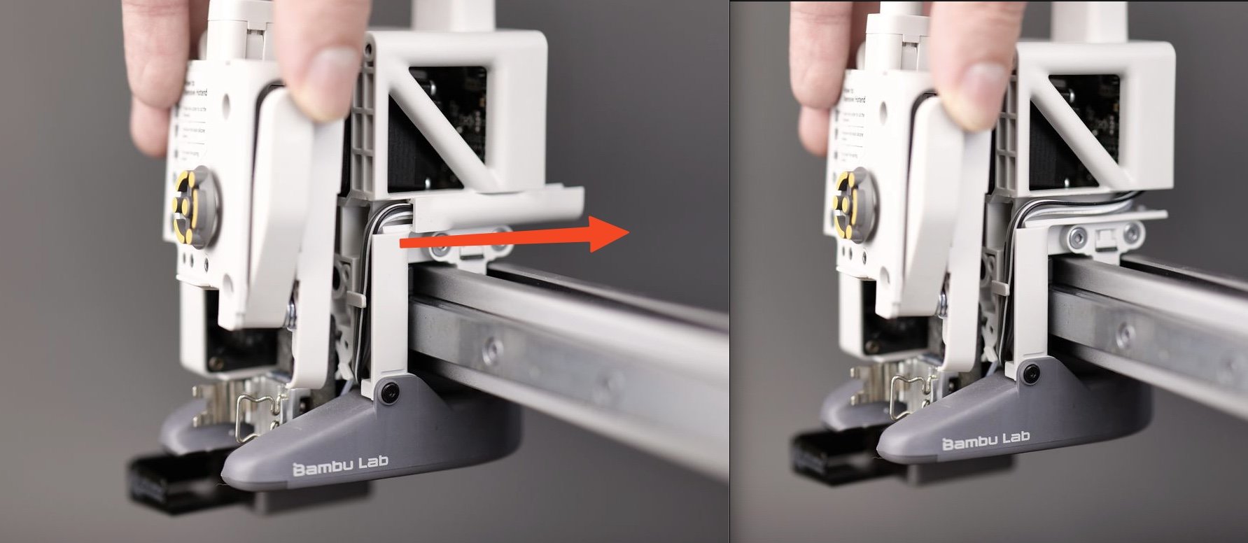
Note: If the part cooling fan cable is blocked by the heating assembly cable in the same cable channel and cannot be removed, you can disconnect the heating assembly connector, loosen the heating assembly cable, and remove the fan cable.

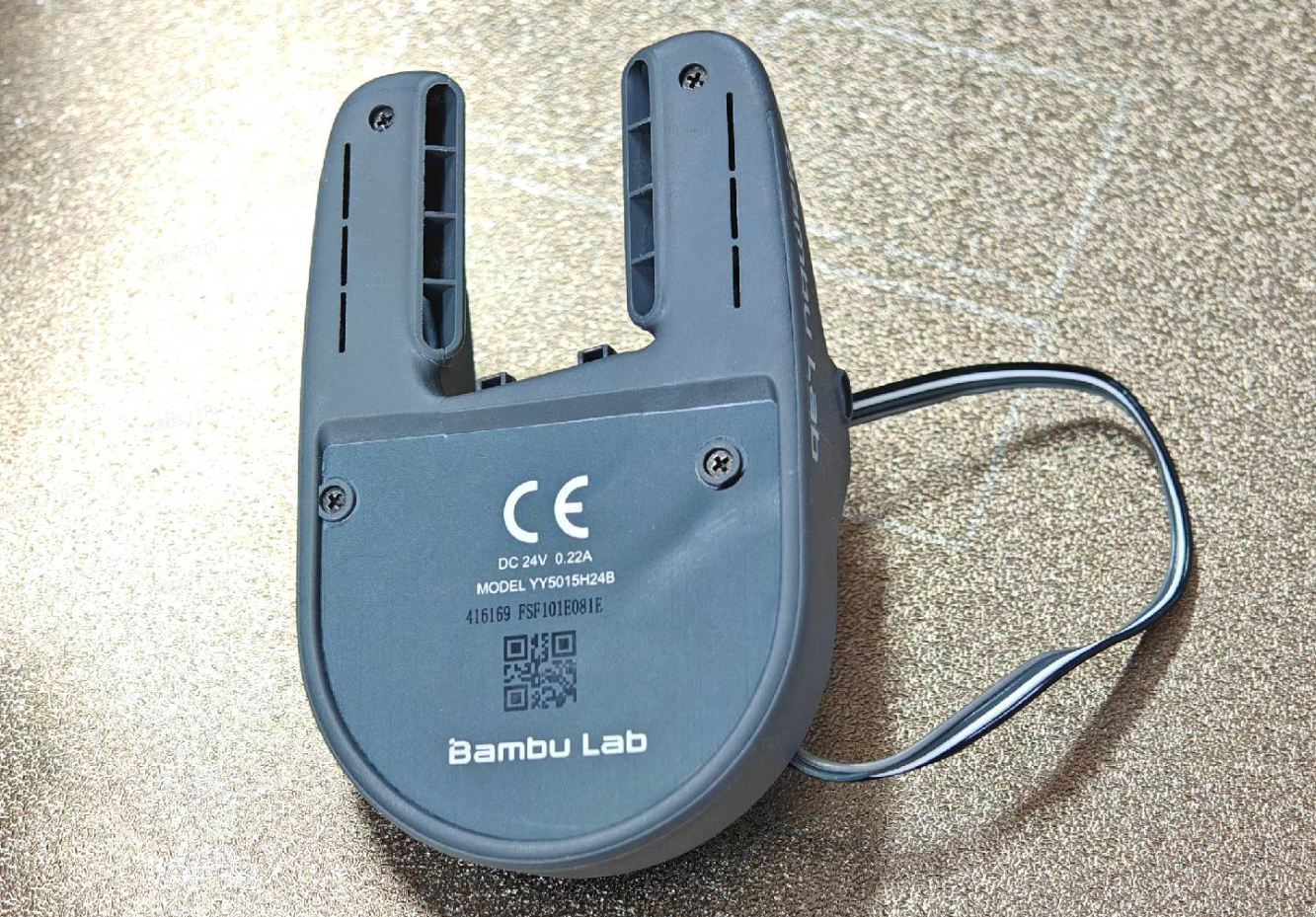
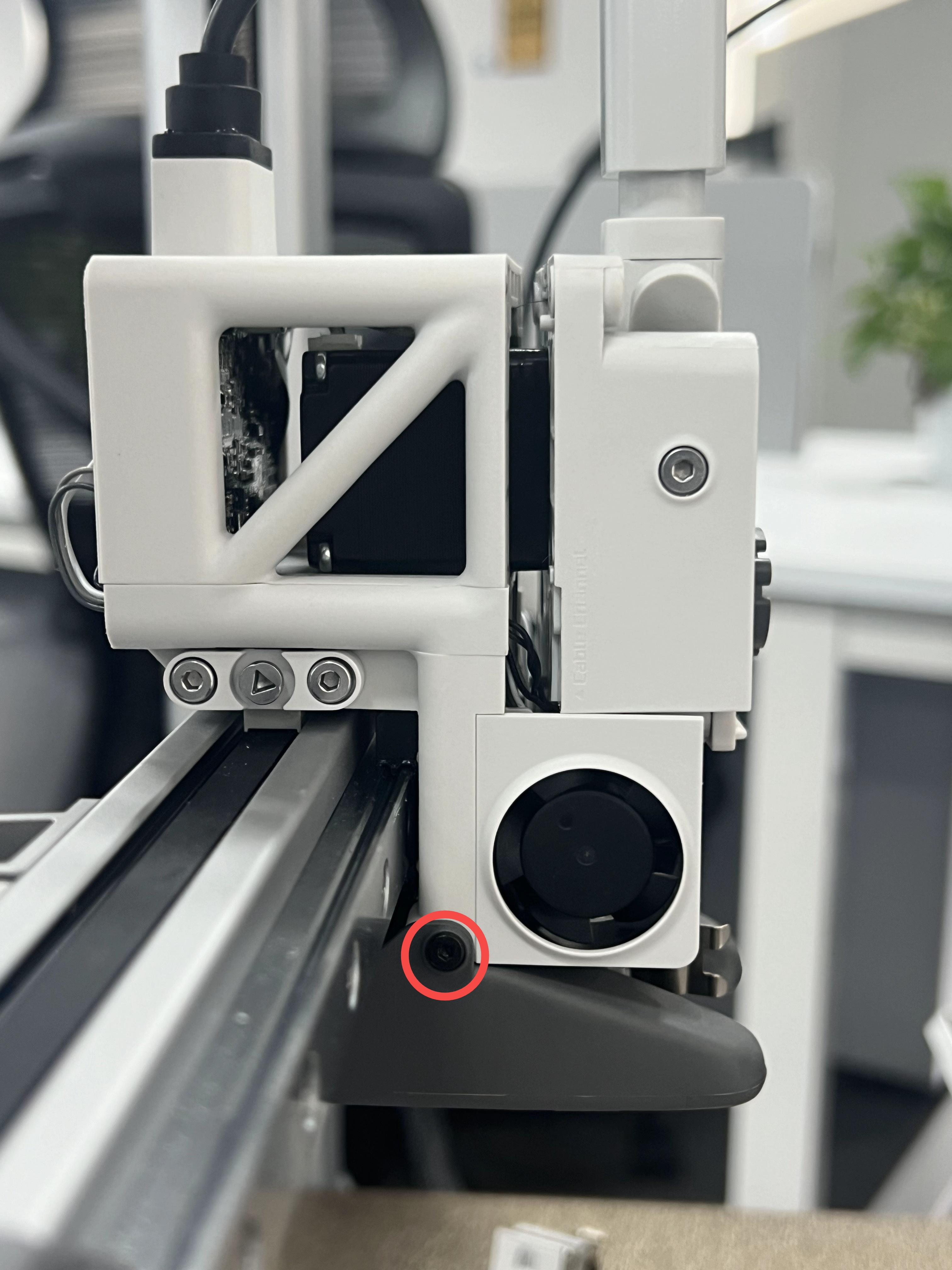
¶ 7. Remove the part cooling fan
Remove the assembly cooling fan by removing the 3 screws securing the fan (two on each side and one on the back).
The model of the three fixed fan screws is BT2*5.
 |
 |
 |
¶ Install the New Part Cooling Fan
¶ 1. Install the New Part Cooling Fan
Install the new part cooling fan onto the toolhead and tighten the 3 screws (two on each side and one on the back) that secure the fan.
|
|
|
¶ 2. Install the right cable cover
Carefully pass the part cooling fan cable through the right cable cover and push the cable cover back in the direction shown.
¶ 3. Install the extruder
Secure the extruder to the toolhead using the 4 screws, as shown in the image below.

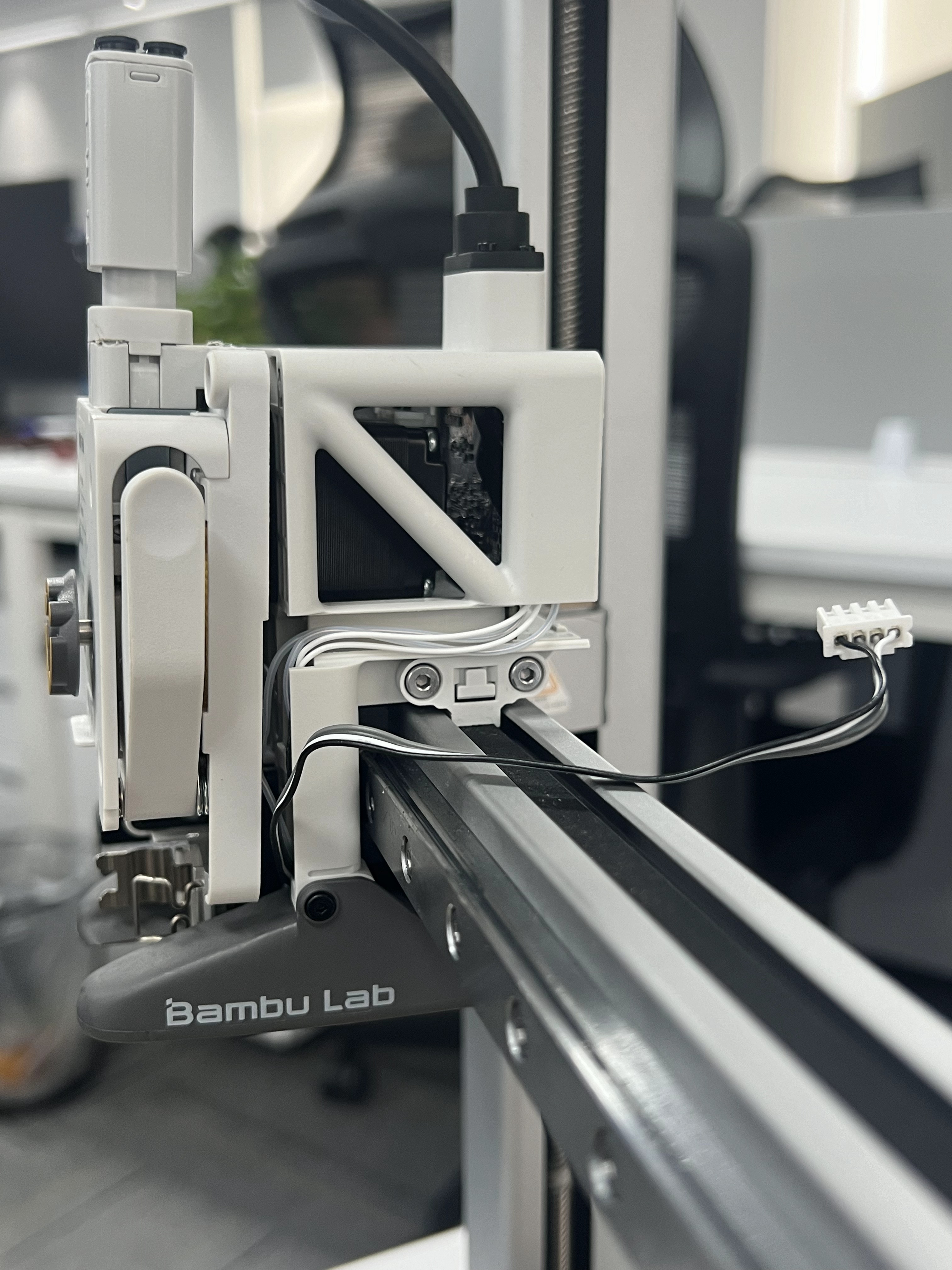
¶ 4. Re-connect the cable
Re-connect the Part Cooling Fan cable as shown below.
Note: If you disconnected the hotend heating assembly cable during disassembly, you will also need to connect the hotend heating assembly cable to the TH board at this time.
¶ 5. Install the toolhead rear housing
Simply align the two brackets on the rear housing towards the top, then push it until you hear a few clicks.
¶ 6. Install the hotend and silicone sock for hotend
Follow the guidance available on the extruder sticker to re-attach the hotend to the toolhead
Then, lock it in place using the clip and install the silicone sock.
¶ 7. Install the toolhead front cover
Simply attach the toolhead front cover on the top of the toolhead by aligning the clips, then gently push on the bottom side. You will hear the clips when the installation is complete.
¶ Verify the functionality
To ensure everything works as expected, turn on the printer and then turn on the part cooling fan.
The new fan should start running.
¶ Calibration step after the operation
We recommend conducting a full calibration of the printer after this operation.
Additionally, it's strongly advised to wash the PEI textured plate before use, as it may have been contaminated during this process.
¶ End Notes
We hope the detailed guide provided has been helpful and informative.
To ensure a safe and effective execution, if you have any concerns or questions about the process described in this article, we recommend reaching out to technical support team before initiating the operation. We will do our best to respond promptly and provide the assistance you need. Click here to open a new ticket in our Support Page.