¶ When to Use This Guide
After connecting the power cord and turning on the printer, the display screen of the printer does not light up.
At the same time, one or more circuit board indicator lights are malfunctioning.
We may observe:
- The screen is off, but the HMS indicator light is on and breathing slowly.
- The screen is off, and the HMS indicator light is also off.
¶ Safety Tips and Tools
- H1.5 hex wrench
- H2.0 hex wrench
- Multimeter (optional)
Important Reminder!
This troubleshooting guide involves many connector plug - ins and pull - outs. Before performing any maintenance or connector plug - in and pull - out work on the printer and its electronic devices (including toolhead cables), please turn off the printer power and disconnect the power supply to avoid short - circuiting due to live operation, which may cause additional electronic device damage and safety hazards.
When you perform maintenance or troubleshooting on the printer, please first confirm the temperature of the hotend and the heatbed to avoid operating at high temperatures. If it is necessary to operate at high temperatures, please wear heat - resistant gloves to ensure safe and effective maintenance work.
¶ Precautions for Troubleshooting
Before starting the troubleshooting process, familiarize yourself with the indicator light patterns of the mainboard (MC), toolhead (TH), and HMS.
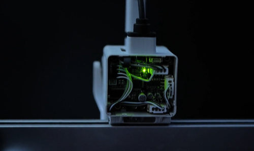
¶ Normal Status: TH Board indicator light constantly green
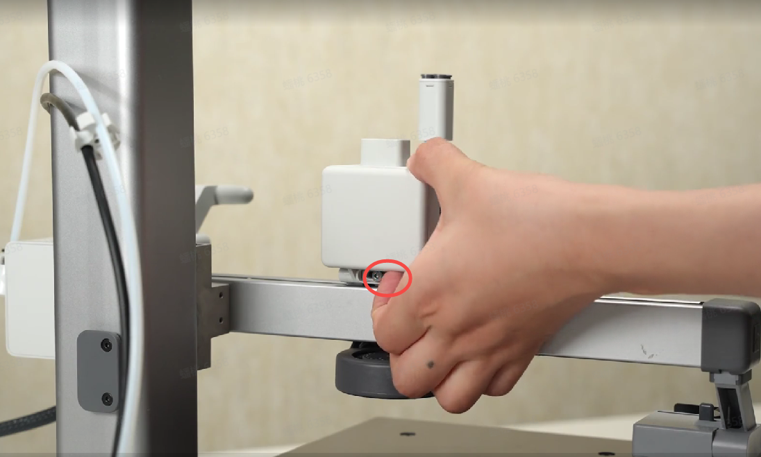
As shown in the photo, hold the bottom of the back cover and carefully pry it open.
https://public-cdn.bblmw.com/wiki/video/A1M-TH.mp4
¶ Normal State: the MC board and AP board are integrated on the mainboard
The MC board flashes green once every 5 seconds (This indicator needs to be observed from a specific angle).
https://public-cdn.bblmw.com/wiki/video/A1M-MC.mp4
The AP board has 1 green indicator light that flashes once per second.
https://public-cdn.bblmw.com/wiki/video/A1M-AP.mp4
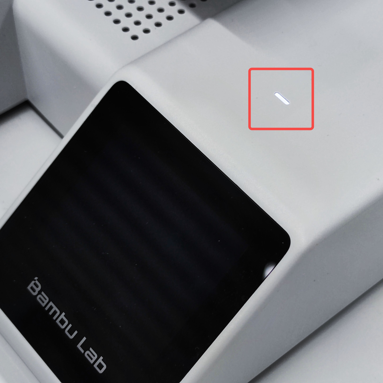
¶ Normal State: the HMS indicator light is on
If there is an HMS error, the indicator light flashes quickly. If there is no HMS error, the indicator light is solid on when the screen is on, and breathes slowly when the screen is off.
¶ Screen Off, HMS Indicator On
¶ Problem Symptoms
After starting the printer, the display screen does not display anything, the HMS indicator light is on and breathing slowly, and the AP and MC mainboard indicator lights are normal.
¶ Troubleshooting Suggestion
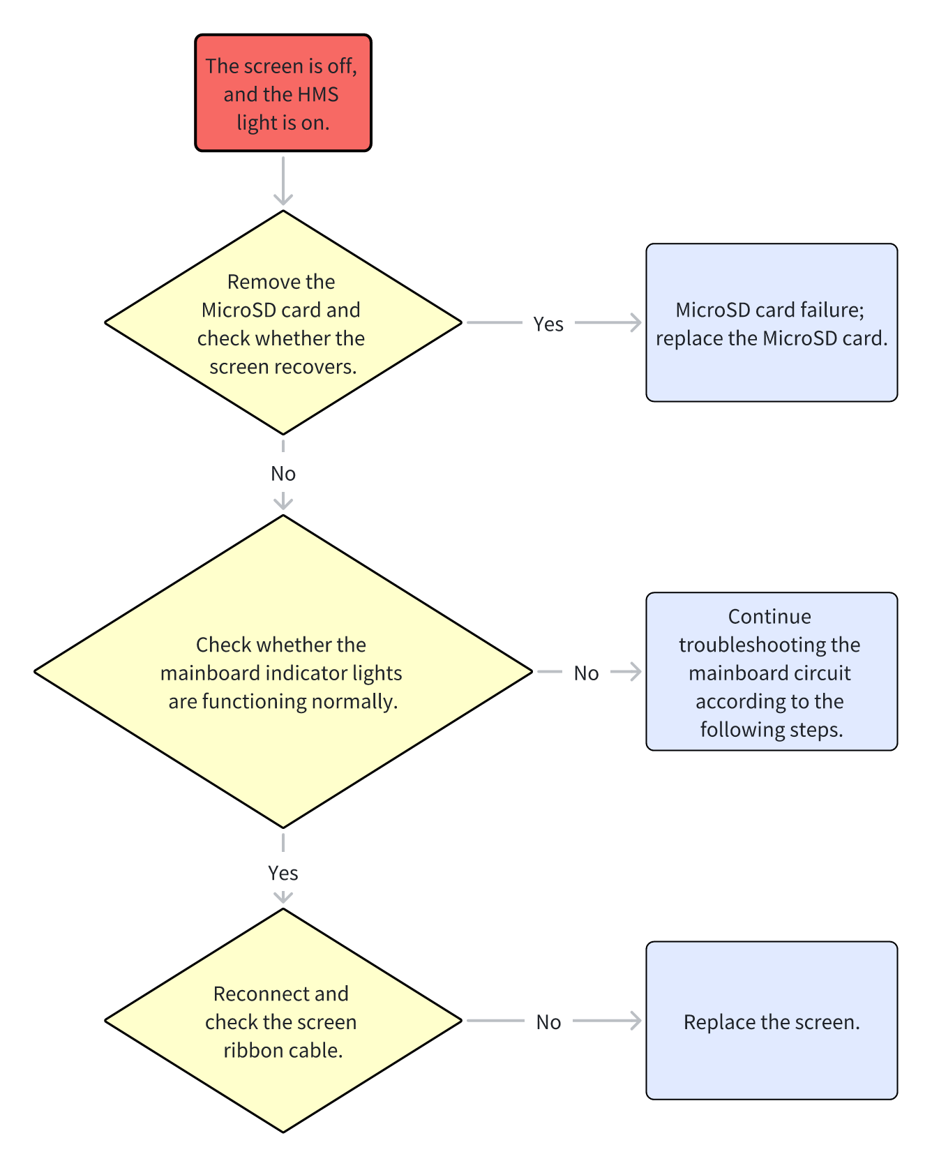
After starting the printer, if the HMS indicator light is on, the issue may be caused by a MicroSD card or the screen. If the problem is not resolved, continue troubleshooting the mainboard circuit.
¶ Causes and Solutions
- The MicroSD card failure causes the screen to not display anything; replace the MicroSD card.
- The screen ribbon cable is loose; reconnect the ribbon cable.
- The screen ribbon cable is damaged; replace the ribbon cable.
- The screen is faulty; replace the screen.
¶ Troubleshooting Steps
¶ 1. Check the MicroSD Card
If the display screen does not display anything, first check the MicroSD card.
Note: Before performing the following operations, be sure to turn off the printer.
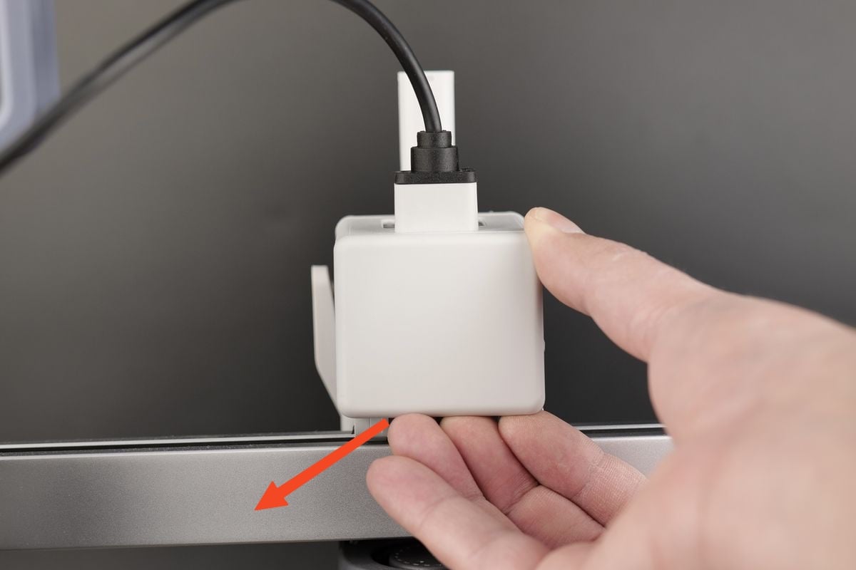
Step 1 - Turn off the printer and carefully remove the MicroSD card. Restart the printer and observe whether the display screen works.
Step 2 - If the display screen works without the MicroSD card, reinsert the MicroSD card while the printer is off and restart to verify whether the previous issue was caused by the card.
Step 3 - If confirmed, replace the MicroSD card.
¶ 2. Check the Display Ribbon Cable
Remove the bottom plate.
If the power indicator, MC, and AP mainboard indicator lights are normal, the issue may be caused by a screen failure or a ribbon cable problem.
Step 1 - Power off and remove the A1 mini bottom plate.
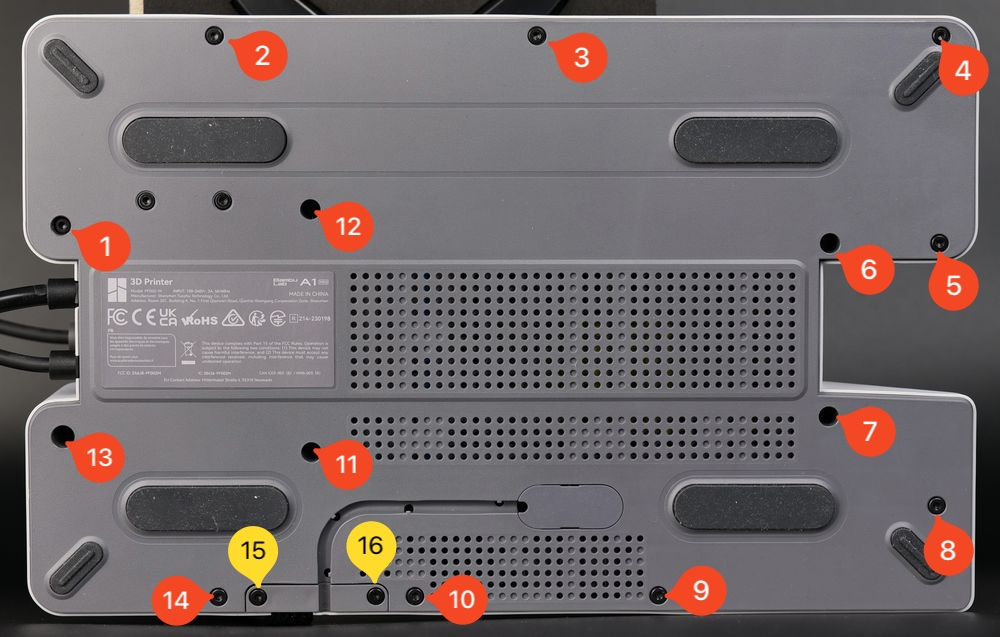
Place the printer on its side so the Z-axis pillar is parallel to the table, and unscrew the 16 screws shown in the figure.
Please note that screws No. 15 and No. 16 are different; remember their positions for reinstalling the bottom cover.
 |
 |
After removing the screws, gently pry out the cover starting from the top right and moving along the edges until it is loose.
Step 2 - After removing the bottom plate, power on the printer again without touching any parts. Observe the indicator lights, then turn off the printer and unplug the power.
Step 3 - If all indicator lights are normal, reconnect the screen ribbon cable and check the interface, pins, and FPC ribbon cable for damage.
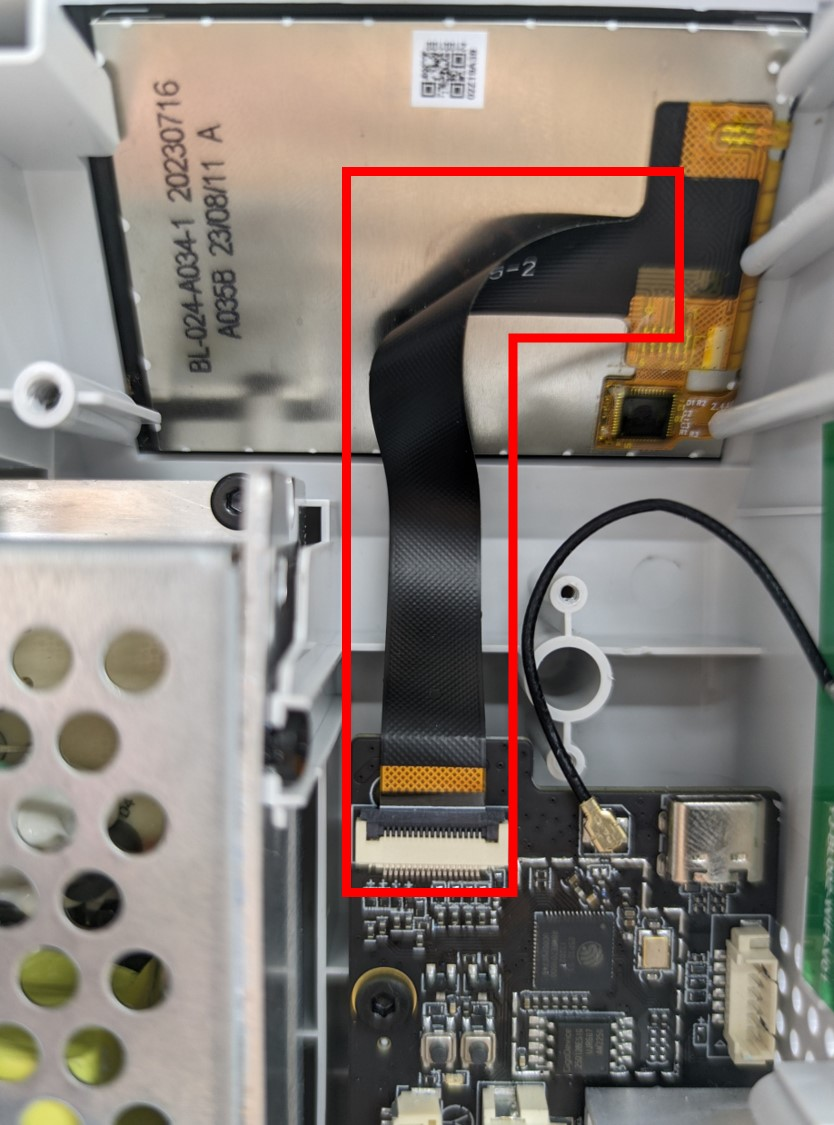 |
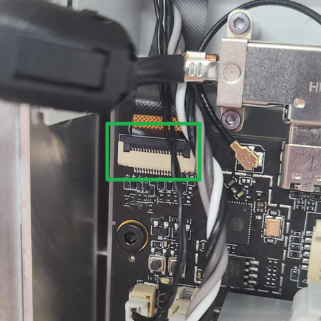 |
Step 4 - If the screen still does not display anything, the screen assembly needs to be replaced.
The A1 mini touchscreen replacement can refer to the Wiki article:Touchscreen Replacement Guide - A1 mini
¶ Screen Does Not Display, HMS Indicator Off
¶ Problem Symptoms
After starting the printer, the display screen does not display anything, and the HMS indicator light is off.
¶ Troubleshooting Suggestion
If the HMS indicator light is off, it indicates a fault in the printer mainboard or power module circuit. It is recommended to troubleshoot the mainboard and TH board circuits.
¶ Causes and Solutions
- Power supply issue; replace the power supply or power connection cable.
- Mainboard power issue; check the mainboard-power connection cable.
- Mainboard failure; replace the mainboard.
- Faulty components on the mainboard causing a short circuit.
- Faulty TH board or its components causing a short circuit.
¶ Troubleshooting Steps
Remove the bottom cover and check the power indicator light, as well as the indicator lights on the MC and AP boards. To troubleshoot the TH board, open the toolhead back cover and observe whether its indicator light is functioning normally.
¶ Power Off and Remove the Bottom Plate to Observe Indicator Lights
¶ 1. Power off and turn off the printer, then remove the A1 mini bottom plate.
Place the printer on its side so the Z-axis pillar is parallel to the table, and unscrew the 16 screws shown in the figure.
Note that screws No. 15 and No. 16 are different; remember their positions for reinstalling the bottom cover.
|
|
After removing the screws, gently pry out the cover starting from the top right and moving along the edges until it is loose.
¶ 2. Observe Indicator Lights
After removing the bottom plate, power on the printer again to observe the indicator lights.Do not touch any printer parts during this process. After observing the indicator lights, turn off the printer and unplug the power.
¶ If the Power Indicator Is Off
¶ 1. Check whether the 24V power module outputs normally.
The printer mainboard input voltage is 24V, supplied by the 24V power module.
If the power module output is abnormal, the input voltage to the mainboard will be abnormal, causing all indicator lights to fail to light. In this case, the power module needs to be replaced.
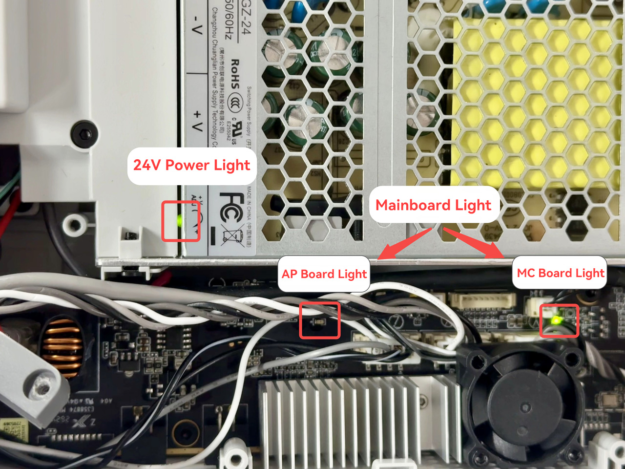
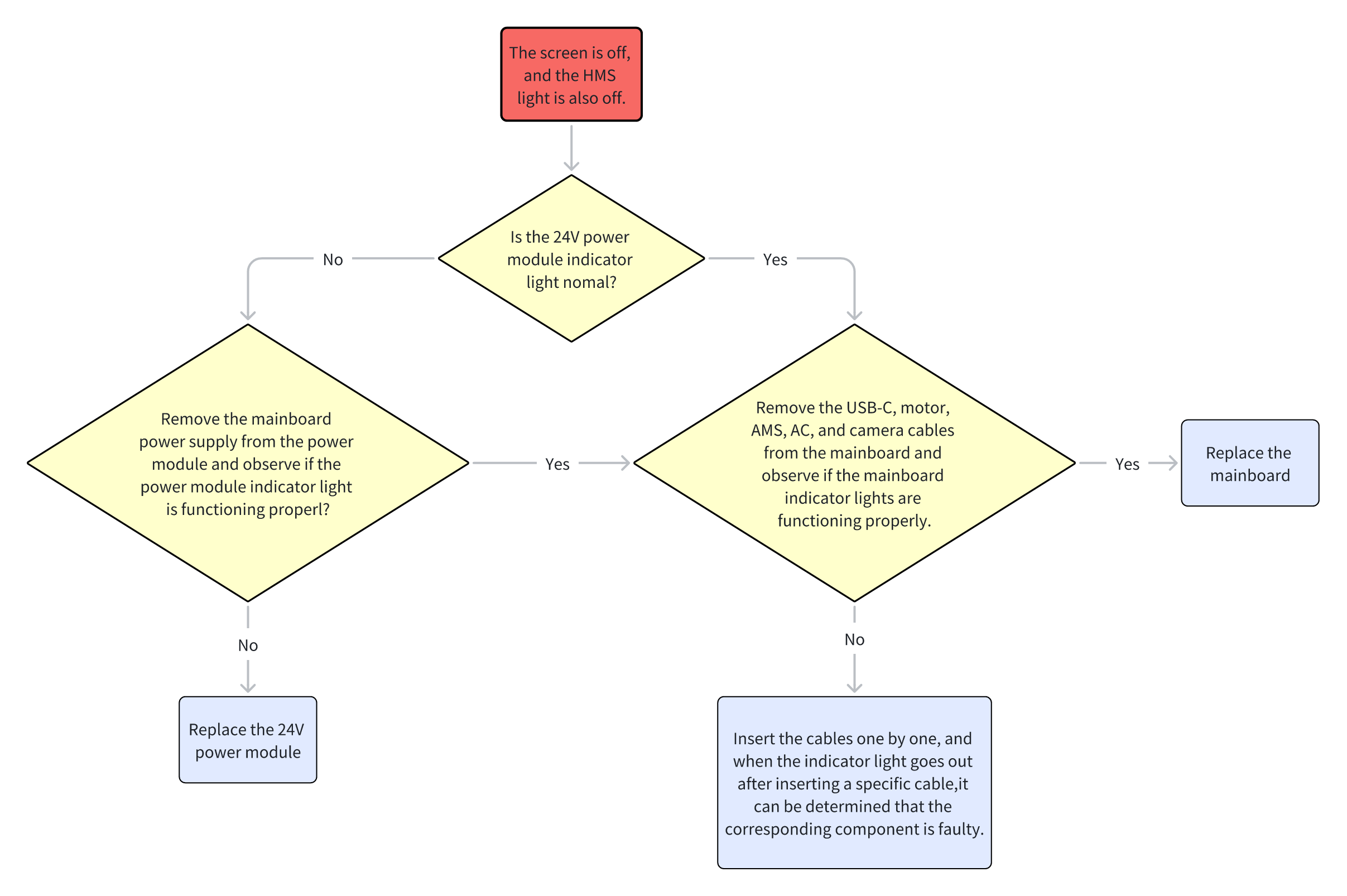
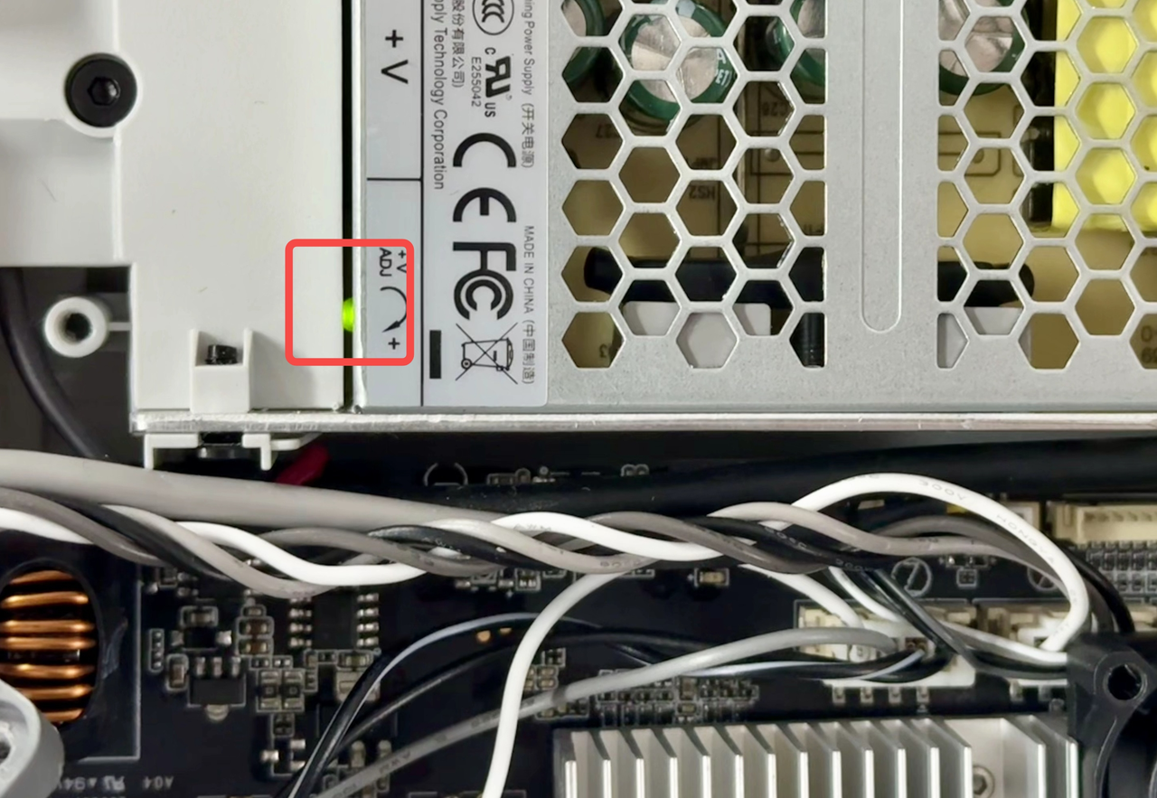
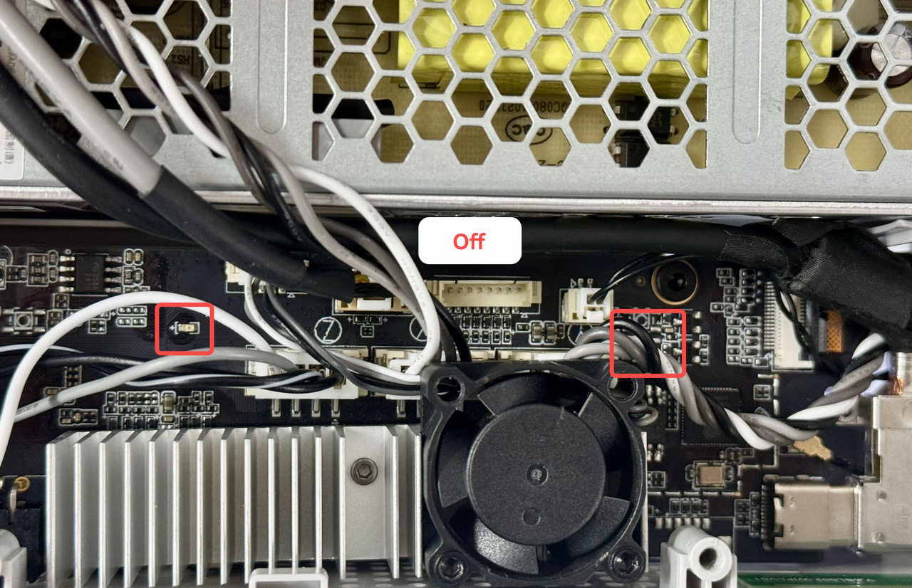
Step 1 - Check the 24V power module indicator light and connector terminals. Normal state: green light is on.
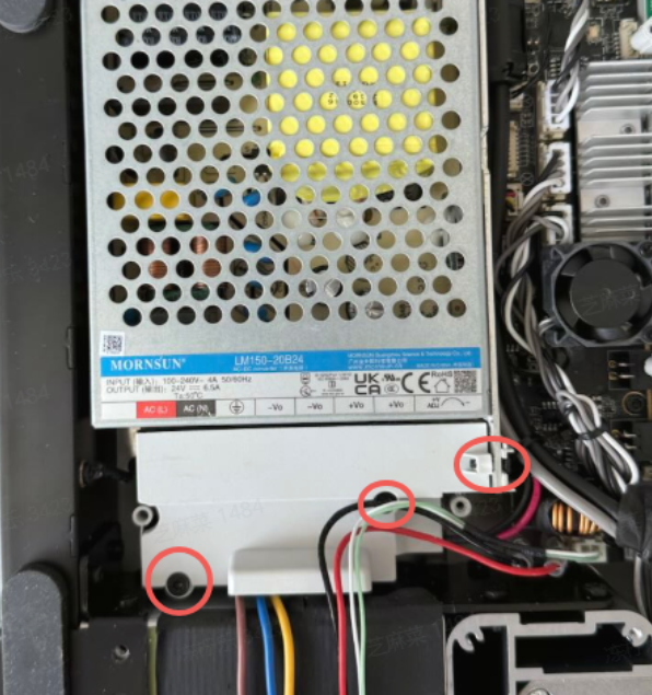
Step 2 - If the indicator light is off or blinking, unscrew the three screws and open the power module for further troubleshooting.
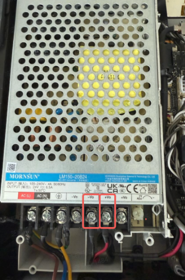
Step 3 - Use a multimeter to measure the voltage between +Vo and -Vo. If the voltage is 0, the power module may be faulty or the mainboard may be short-circuited.
If no multimeter is available, loosen the two screws shown in the figure and remove the mainboard power cable. At this time, the power module is free from external interference. Plug in the power and turn on the printer.
If the indicator light is still abnormal, the power module is faulty and should be replaced.
Note: Do not touch any printer parts during power-on. After observing the indicator lights, turn off the printer and unplug the power.
¶ 2. Check Whether the Mainboard Outputs Normally
If removing the mainboard power cable restores the power indicator and provides 24V output, a short circuit on the mainboard or a downstream circuit board may be the cause.
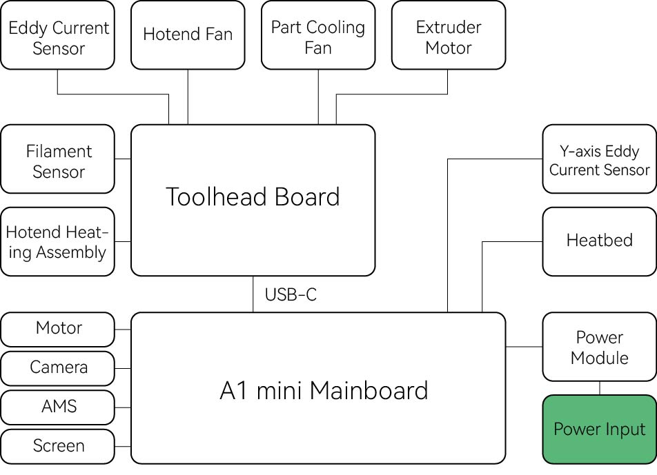
The 24V power system inside the printer is connected in series. If any component in the main circuit or branch circuit (mainboard, toolhead mainboard, or components on the boards such as fans, heaters, motors, etc.) has a short circuit, the entire 24V system may be short-circuited.
¶ If the Power Indicator Is On but Mainboard Indicator Lights Are Abnormal
- The mainboard power connection cable is damaged.
- The secondary circuit of the mainboard has a short circuit.
- The mainboard is faulty.
¶ 1. Mainboard Power Issue: Check the Mainboard-Power Connection Cable
If you have a multimeter at home, you can try measuring the voltage at these two terminals on the mainboard (optional). This is the DC power input of the mainboard. If it reads 0, it indicates that the mainboard power connection cable may be damaged.
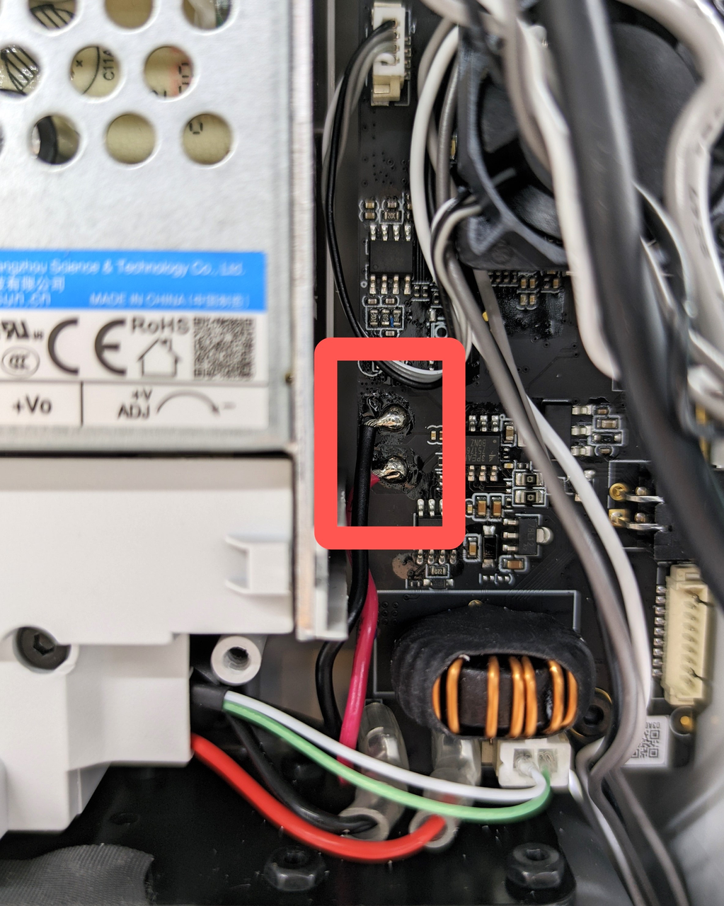
¶ 2. Mainboard Fault or Component Issue Causing Short Circuit
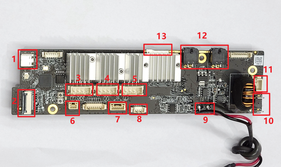
| A1 mini Mainboard | |||
|---|---|---|---|
|
|||
| No. | Name | No. | Name |
| 1 | Toolhead USB-C Cable | 8 | Mainboard Cooling Fan |
| 2 | Screen | 9 | Mainboard Power |
| 3 | Y Motor | 10 | Heat Transfer Power |
| 4 | X Motor | 11 | Heated Bed Signal Cable |
| 5 | Z Motor | 12 | AMS Lite |
| 6 | Y Inductive Sensor | 13 | SD Card Slot |
| 7 | Live Camera | ||
Step 1 - Power off, disconnect all component cables from the mainboard, then turn on the printer to test whether the mainboard indicator lights function normally.
If the mainboard is normal, the two indicator lights on the mainboard will light up correctly. If they still do not light up properly, the mainboard is faulty. Please refer this wiki article for replacement: Mainboard Replacement Guide - A1 mini。
Step 2 - If the mainboard indicator lights work again, it indicates that other components on the mainboard have a short circuit or the TH board is faulty.
Reconnect the component cables to the mainboard one by one and power on to check whether the indicator lights recover, in order to identify which component has a short circuit and replace the corresponding component.
Note: Keep the printer powered off when connecting or disconnecting components to avoid damaging the mainboard.
Step 3 - If after reconnecting the TH board ribbon cables the mainboard indicator lights turn off or blink, this indicates that the problem is caused by a TH board fault and further troubleshooting of the TH board is required.
¶ 3. TH Board or Its Components Causing Short Circuit
Open the toolhead rear cover and observe the TH board indicator light.
If the indicator light is steadily green, the TH board may be faulty. Please refer this wiki article for replacement: TH Board Replacement Guide - A1 mini.
If the indicator light is off, power off and disconnect all component cables from the TH board, then power on to see if the indicator light recovers.
 |
 |
Step 1 - If the indicator light recovers, it indicates that there is a component short circuit on the TH board.
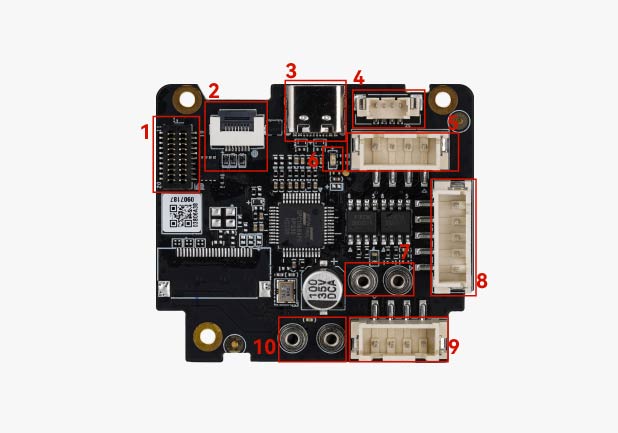
| A1 mini Toolhead Board Overview | |||
|---|---|---|---|
|
|||
| No. | Name | No. | Name |
| 1 | Hotend Heating Assembly | 6 | TH Board Indicator Light |
| 2 | Filament Sensor | 7 | Nozzle Eddy Sensor |
| 3 | USB-C | 8 | Hotend Fan |
| 4 | Empty | 9 | Part Cooling Fan |
| 5 | Extruder Motor | 10 | Empty |
Reconnect the TH board component cables one by one and power on to check whether the indicator light recovers, in order to identify which component has a short circuit and replace the faulty component.
Note: Keep the printer powered off when connecting or disconnecting components to avoid damaging the mainboard.
Step 2 - If the indicator light does not recover, the TH board is faulty.
Please refer this wiki article for replacement: TH Board Replacement Guide - A1 mini.
¶ End Notes
We hope the detailed guide provided has been helpful and informative.
If this guide does not solve your problem, please submit a support ticket. We will answer your questions and provide assistance.
If you have any suggestions or feedback on this Wiki, please leave a message in the comment area. Thank you for your support and attention!