¶ Extruder Motor
In this guide, we will demonstrate the replacement process for the A1 extruder motor.
¶ Compatible Printer Models
A1, A1 mini
¶ When to use?
- Motor stall and step loss
- Extrusion has significant fluctuations
- Recommended by Bambu Lab Technical Support
¶ Safety Warning
It's crucial to power off the printer before conducting any maintenance work, including work on the printer's electronics and tool head wires. Performing tasks with the printer on can result in a short circuit, leading to electronic damage and safety hazards.
During maintenance or troubleshooting, you may need to disassemble parts, including the hotend. This exposes wires and electrical components that could short circuit if they contact each other, other metal, or electronic components while the printer is still on. This can result in damage to the printer's electronics and additional issues.
Therefore, it's crucial to turn off the printer and disconnect it from the power source before conducting any maintenance. This prevents short circuits or damage to the printer's electronics, ensuring safe and effective maintenance. For any concerns or questions about following this guide, open a new ticket in our Support Page and we will do our best to respond promptly and provide the assistance you need.
¶ Tools and materials needed
- H2.0 hex wrench
- H1.5 hex wrench
- 25 minutes
¶ Remove the old extruder motor
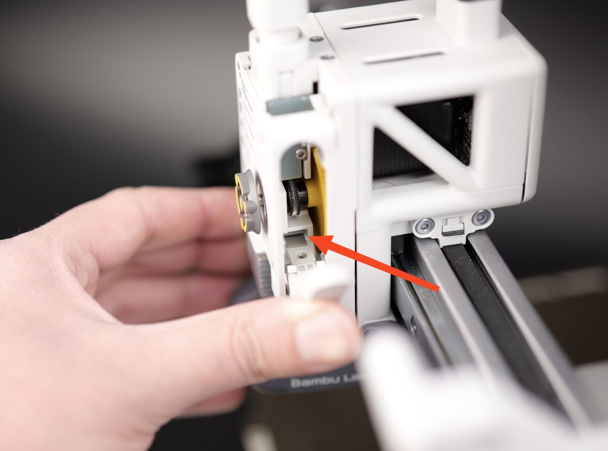
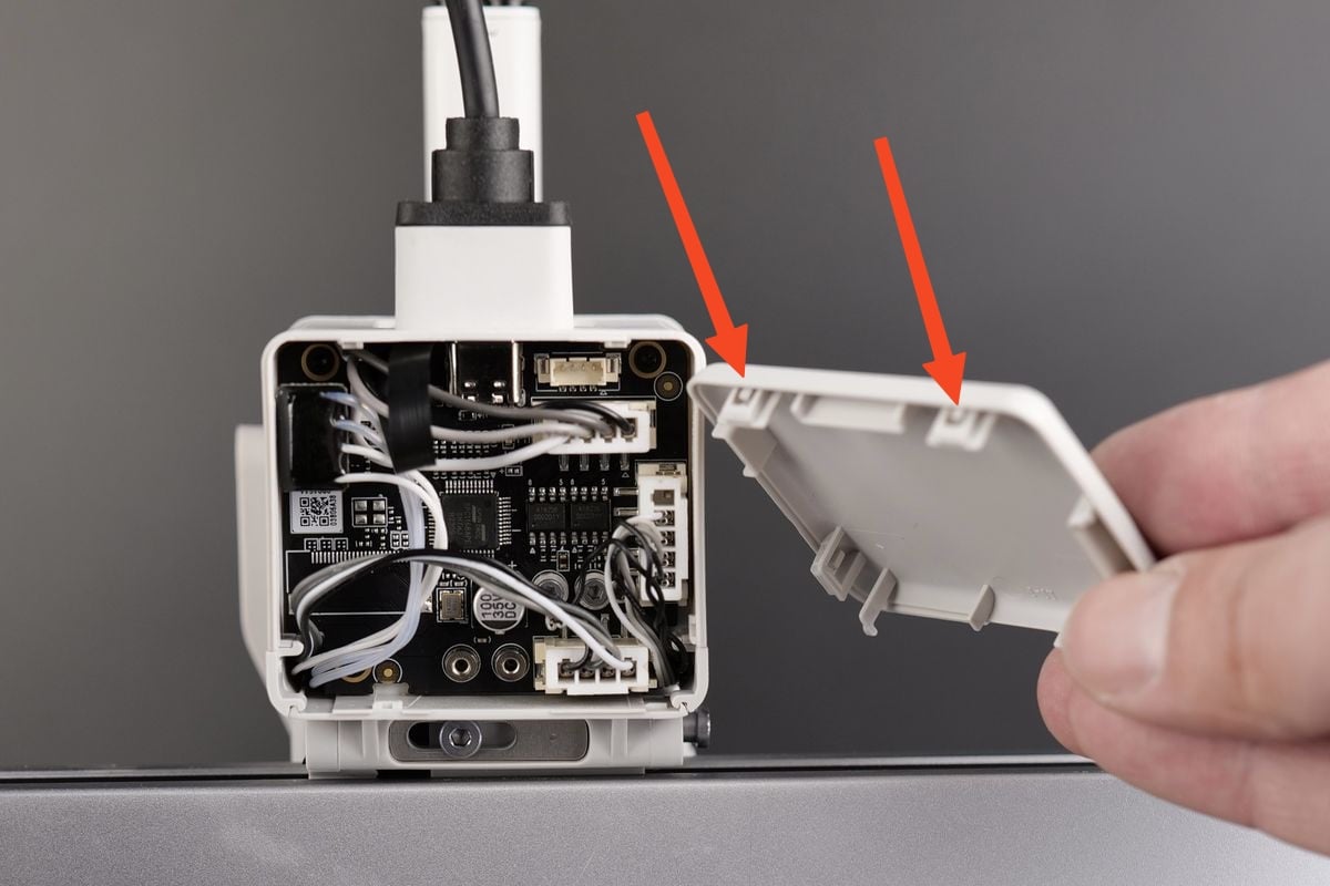
¶ 1.Remove the toolhead rear cover
Please carefully engage the latch at the bottom of the rear cover as shown below, and gently pull it backward to open the cover.
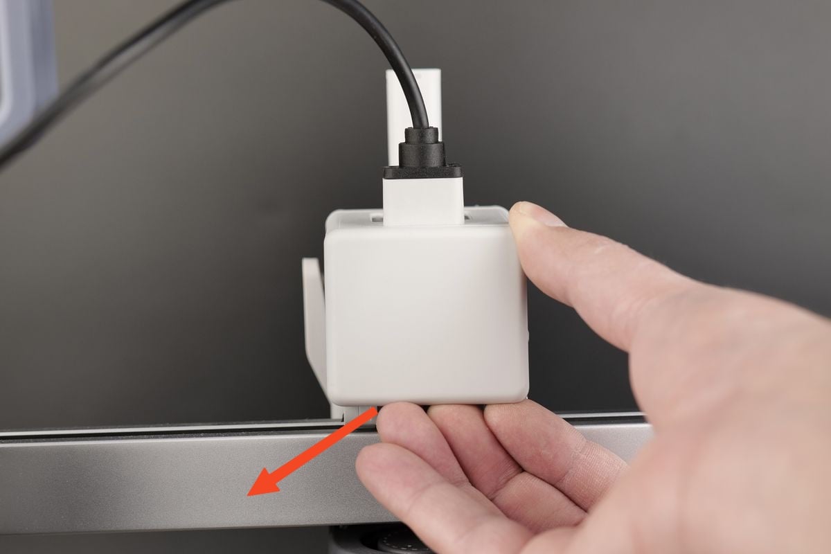
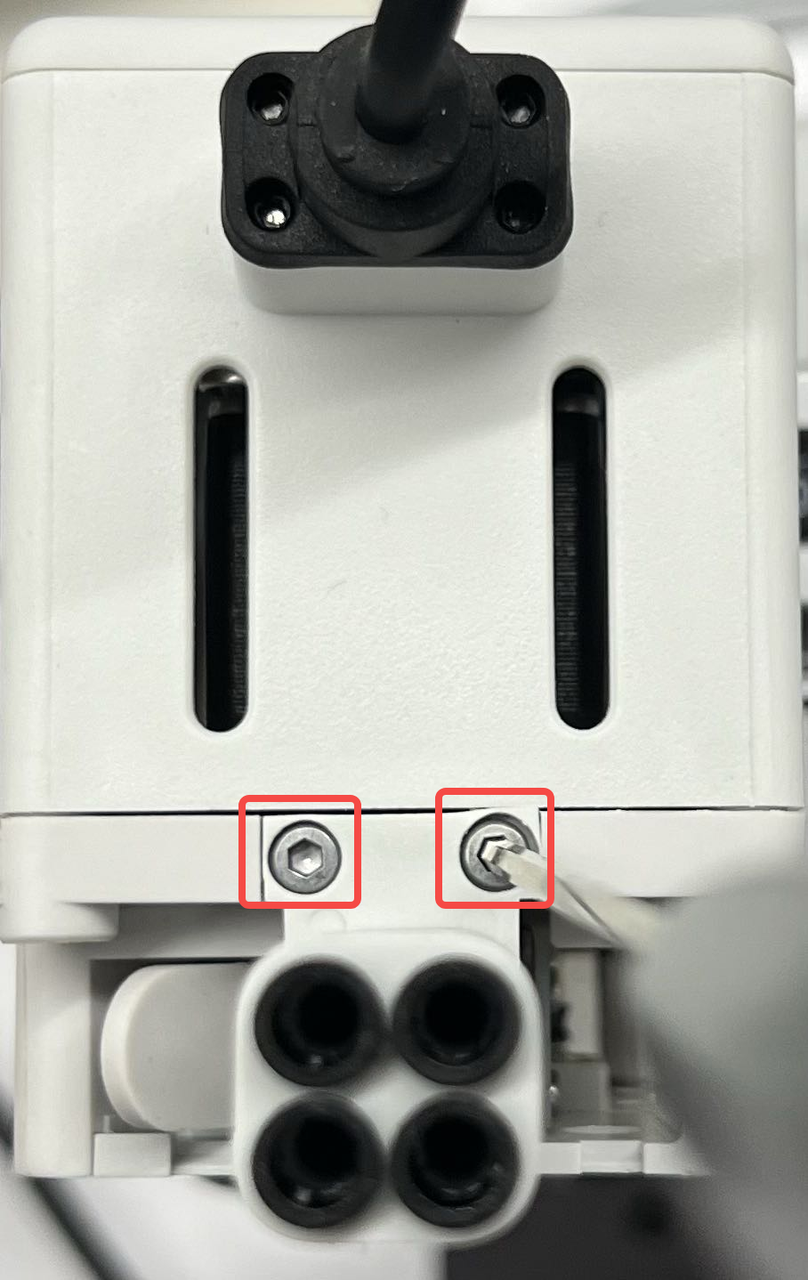
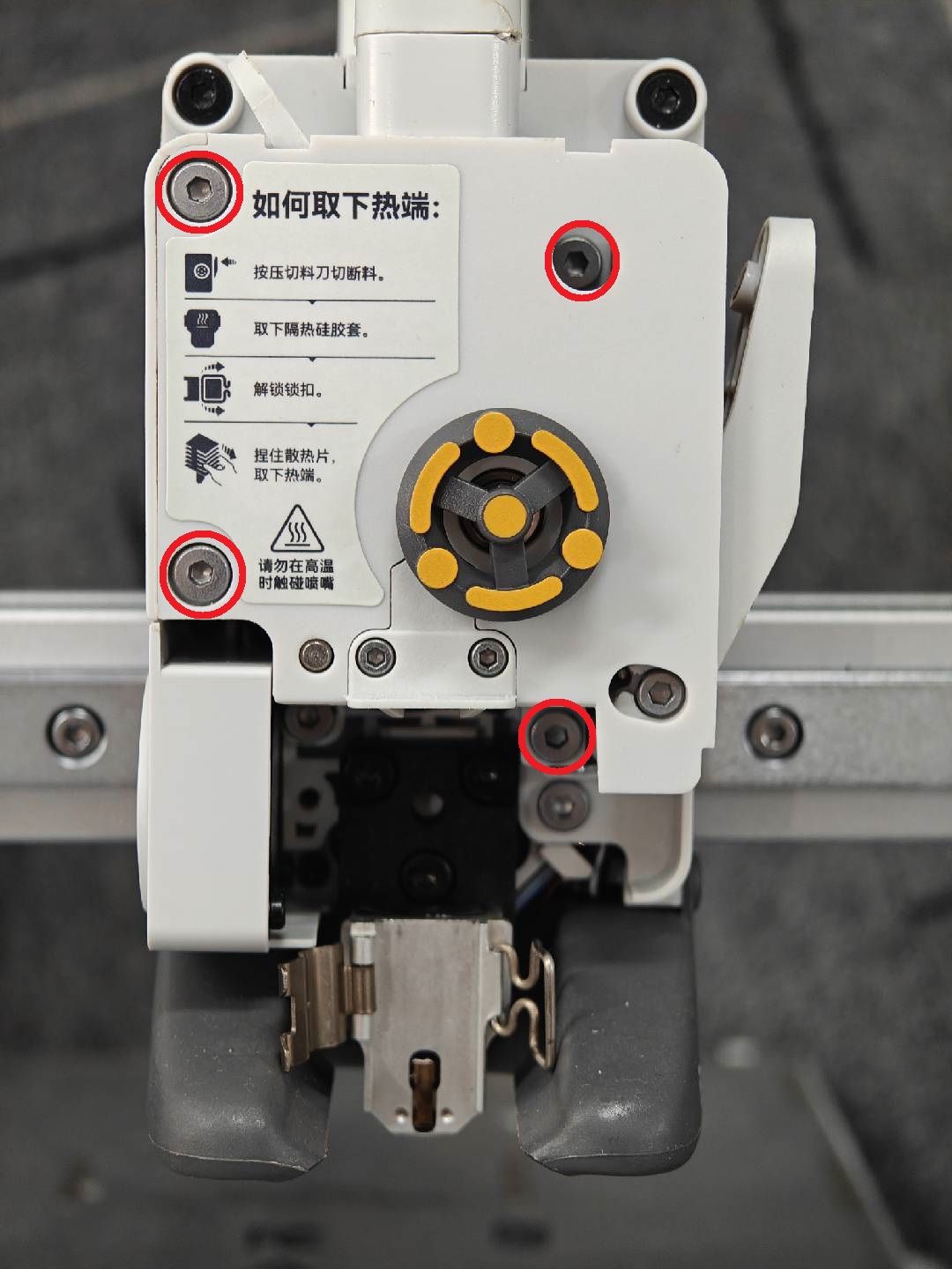
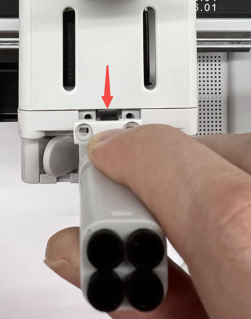
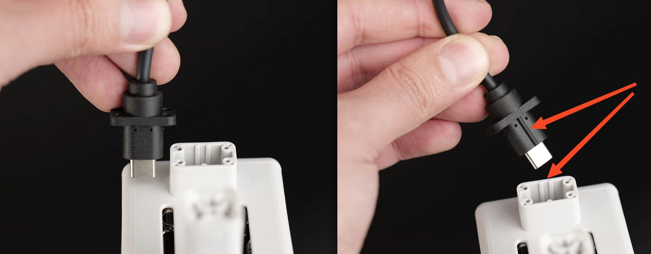
¶ 2.Unplug the USB-C cable
Use an H1.5 Allen key to remove the four screws securing the USB-C data cable on the A1 toolhead, and then lift the USB-C data cable up to remove it.
¶ 3.Remove the TH Board screws
Remove the three black screws holding the TH board in place.
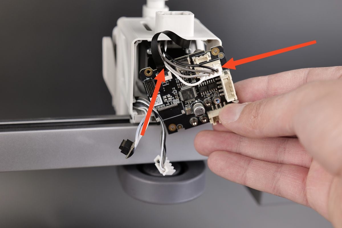
¶ 4.Disconnect the cables
Next, remove the four cables attached to the TH Board.
Carefully pull them out by the connector, and avoid pulling the cables from the connectors.
We recommend using a flat tool to gently pry them out to avoid any potential damage.
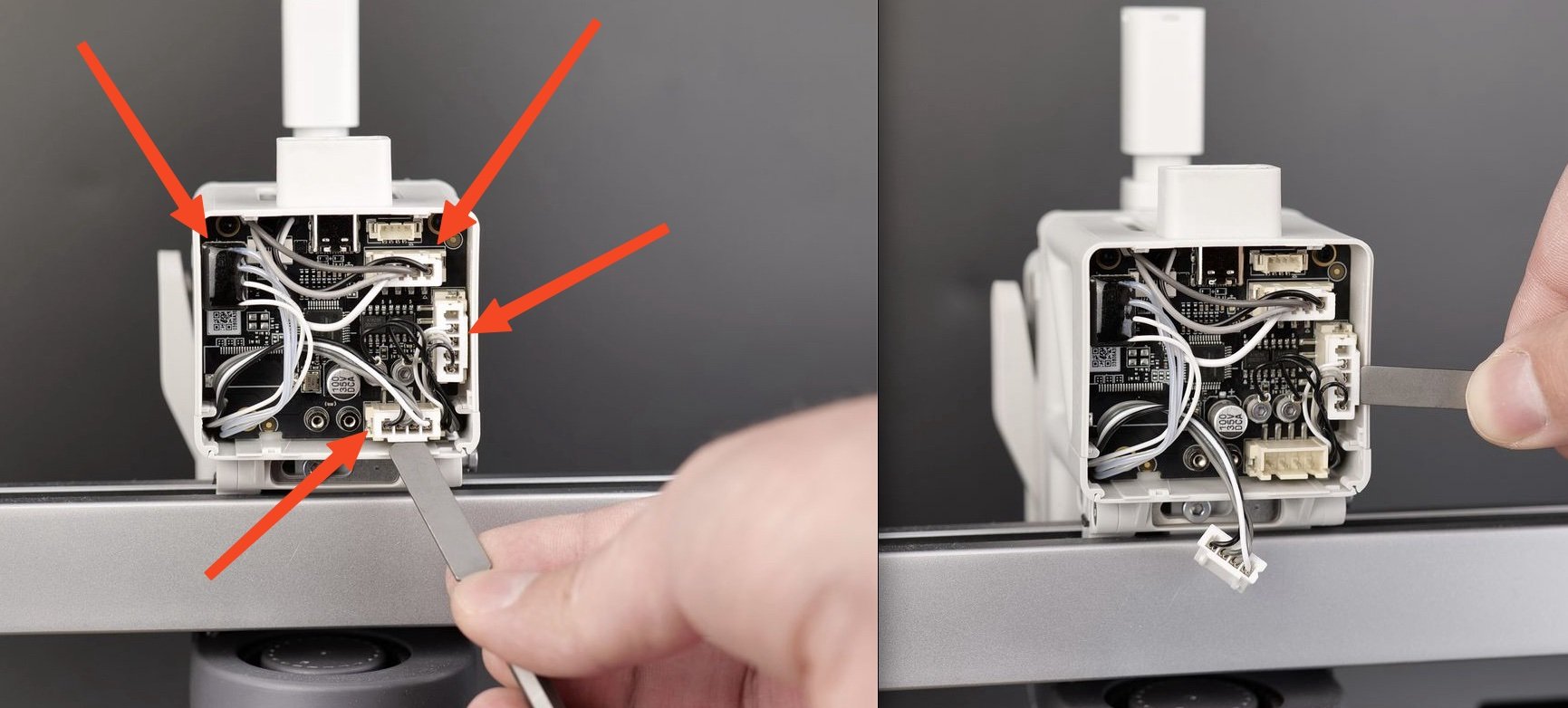
Don't forget to also remove the eddy current coils which are held in place by two screws.
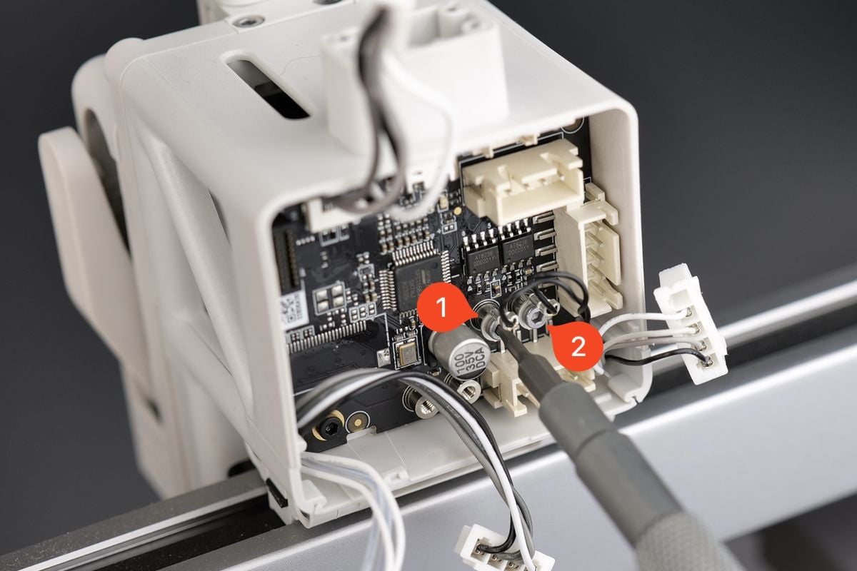
¶ 5.Remove the TH board
You can now remove the TH Board from the plastic housing.
Be careful when pulling it out, as you will need to carefully disconnect the filament sensor FPC.
Pull it slowly and straight upwards. Avoid wiggling the ribbon cable as it can cause damage to it. If you have damaged it, you can order a replacement from this link
¶ 6.Remove the toolhead front cover
Grab the base of the front cover and gently pull towards you.
The clips holding the cover in place will be released, allowing you to remove the front cover.

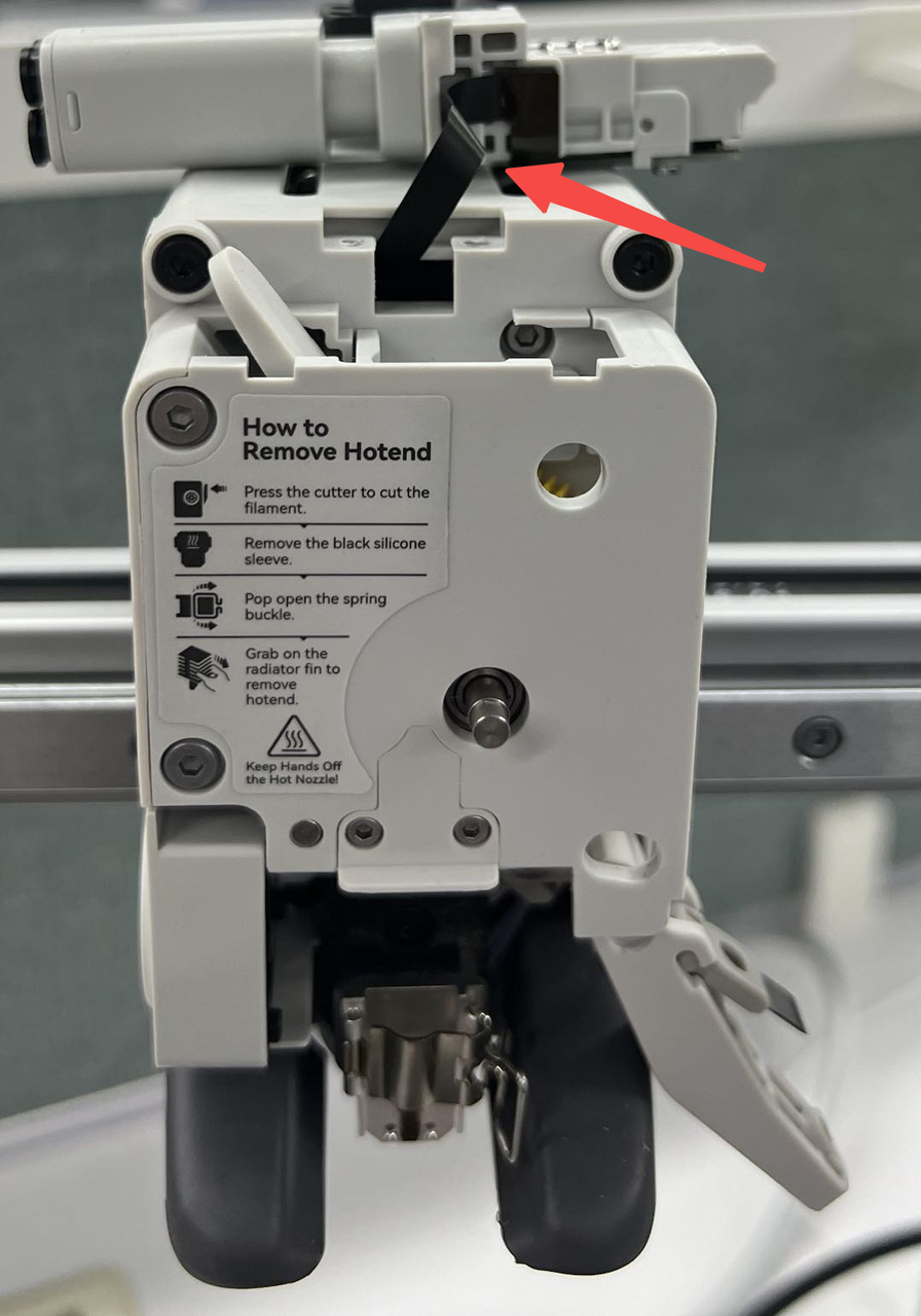
¶ 7.Release the filament cutter lever
The next step is to release the filament cutter lever. To do it, start by holding the filament cutter pressed to allow for easy removal of the single screw holding it in place.
Keep holding the lever pressed until the screw is completely removed, then gently release the cutter.
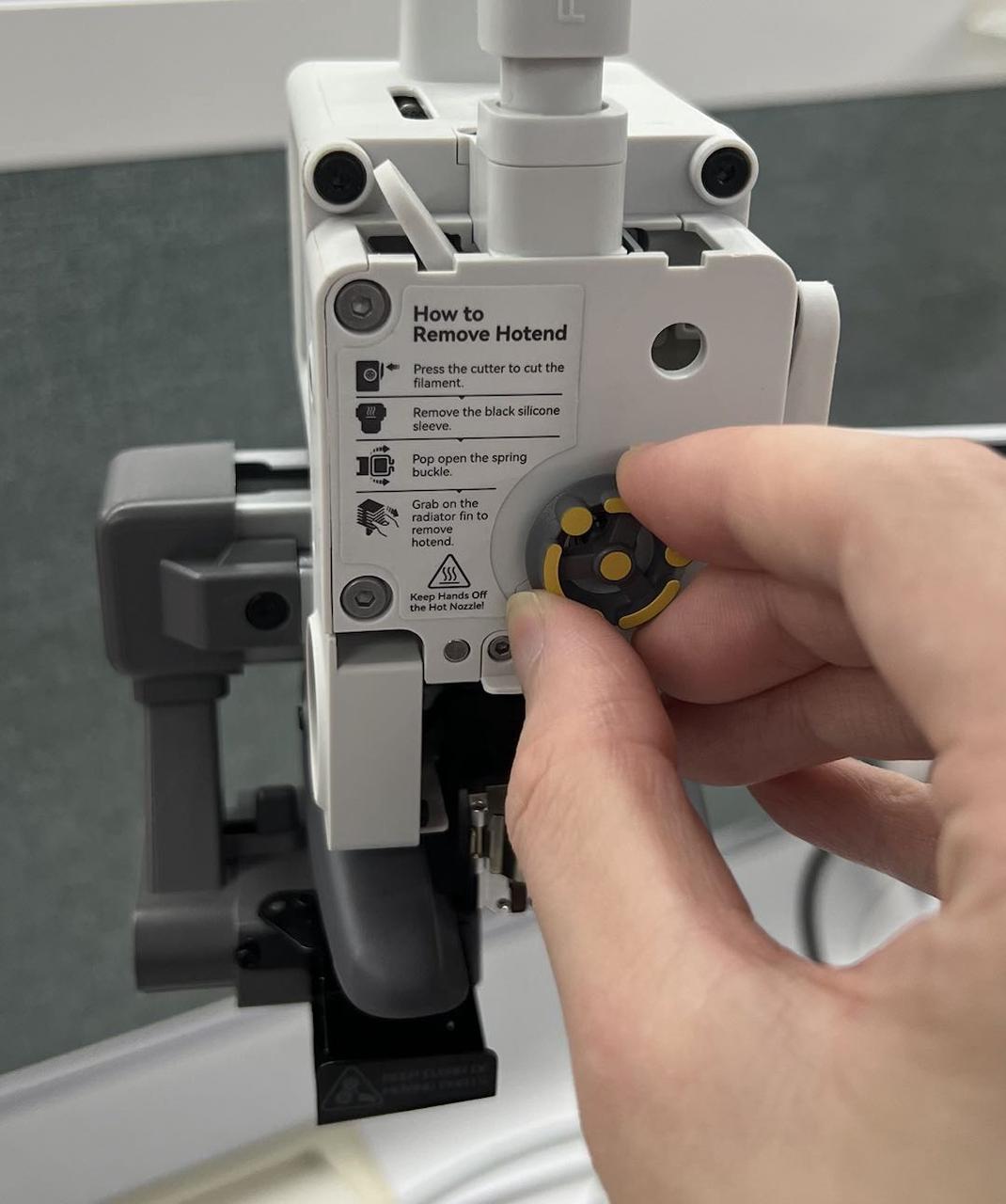
¶ 8.Remove the Extruder Pressure Block
Remove the rotating wheel. Take off the pressure block by using a H1.5 Allen key to unscrew two screws.
 |
 |
¶ 9.Remove the Nozzle Assembly
Remove the silicone sock for hotend, release the clip, and detach the nozzle assembly.
After completing this step, you can proceed to remove the extruder front cover in the next step.
 |
 |
¶ 10.Remove the filament hub assembly
Use an H2.0 Allen key to unscrew two screws and then take out the filament hub. Please be careful not to damage the black FPC cable. After removing the filament hub, you can place it on top of the toolhead as shown in the picture.
 |
 |
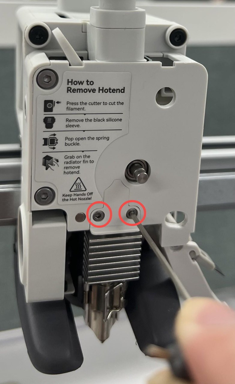
¶ 11.Remove the Extruder Front Cover
Next, to remove the extruder front cover, first take out the four securing screws on the front cover; then loosen the side screw (do not remove it completely to prevent the internal spring washer from falling out), and the front cover can be detached.
 |
 |
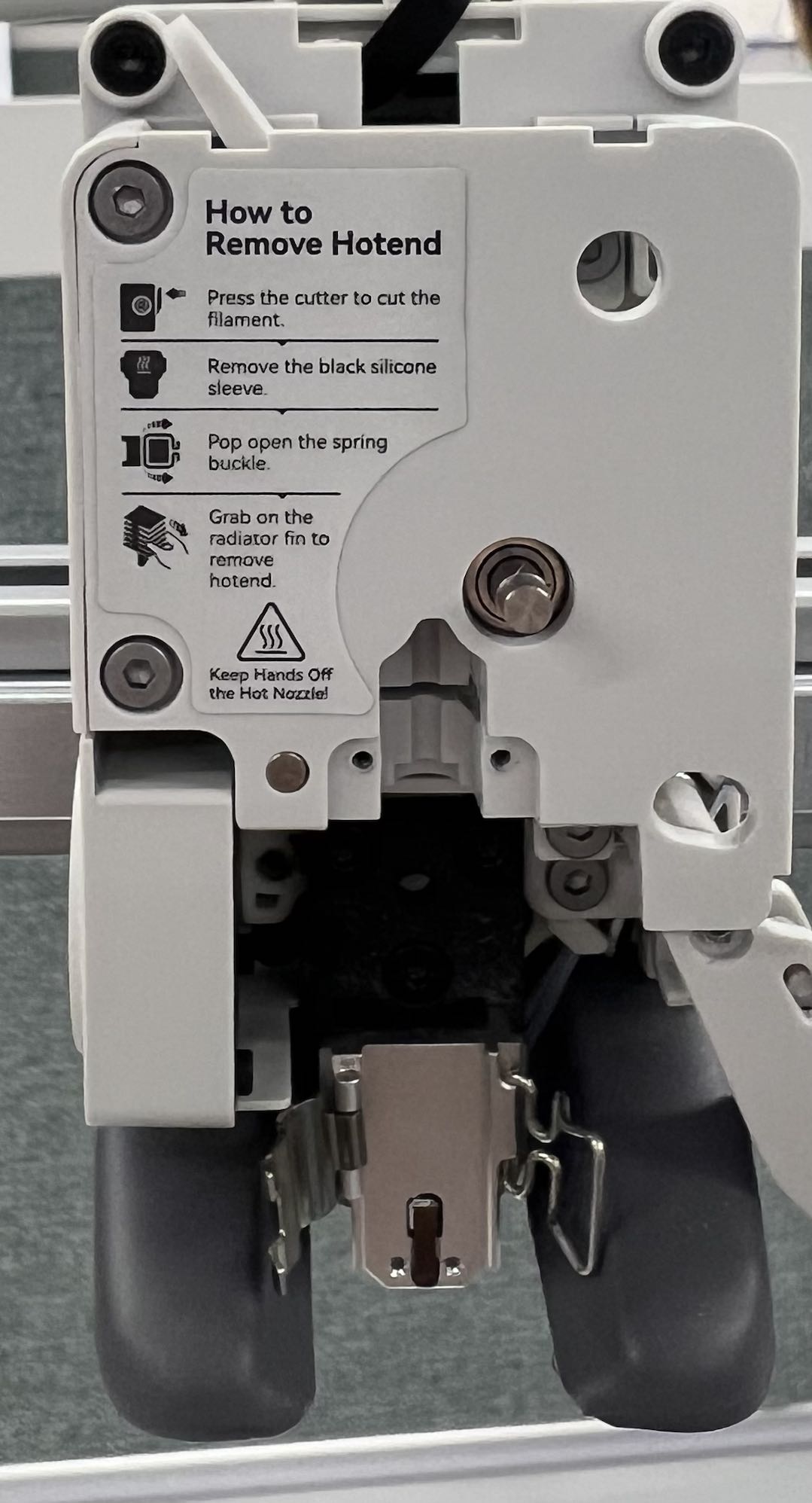
¶ 12.Remove the Extruder Gear
After removing the front cover, completely remove the side screw, take out the washer and spring, and then remove the extruder gear.
 |
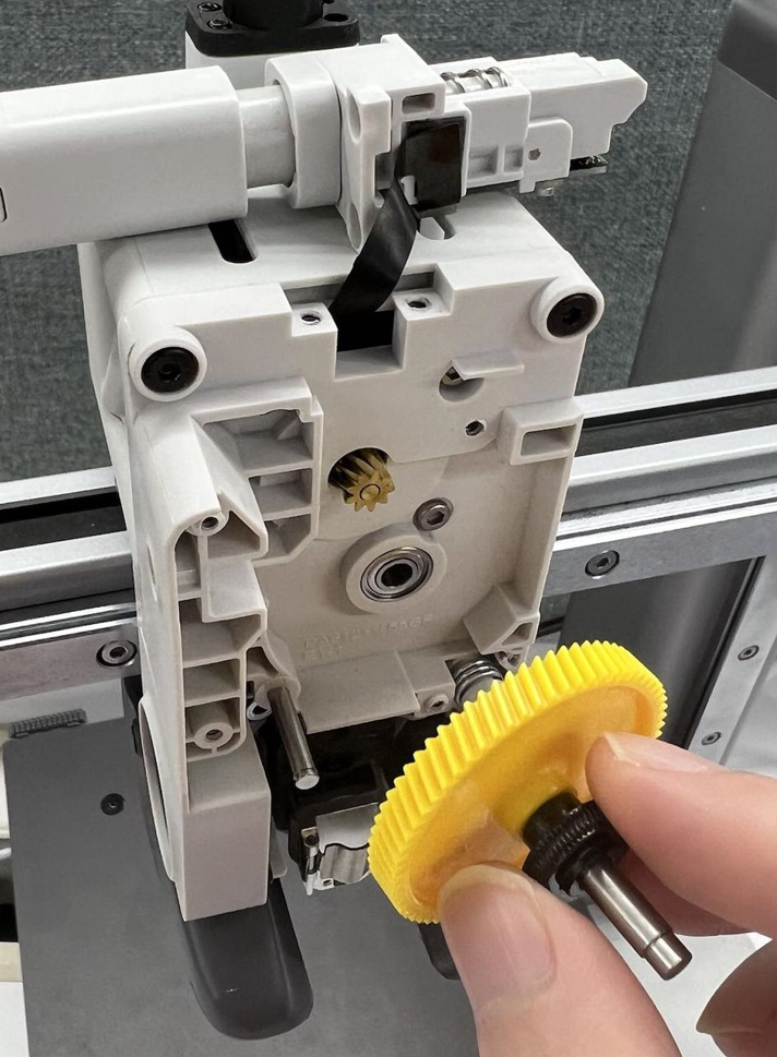 |
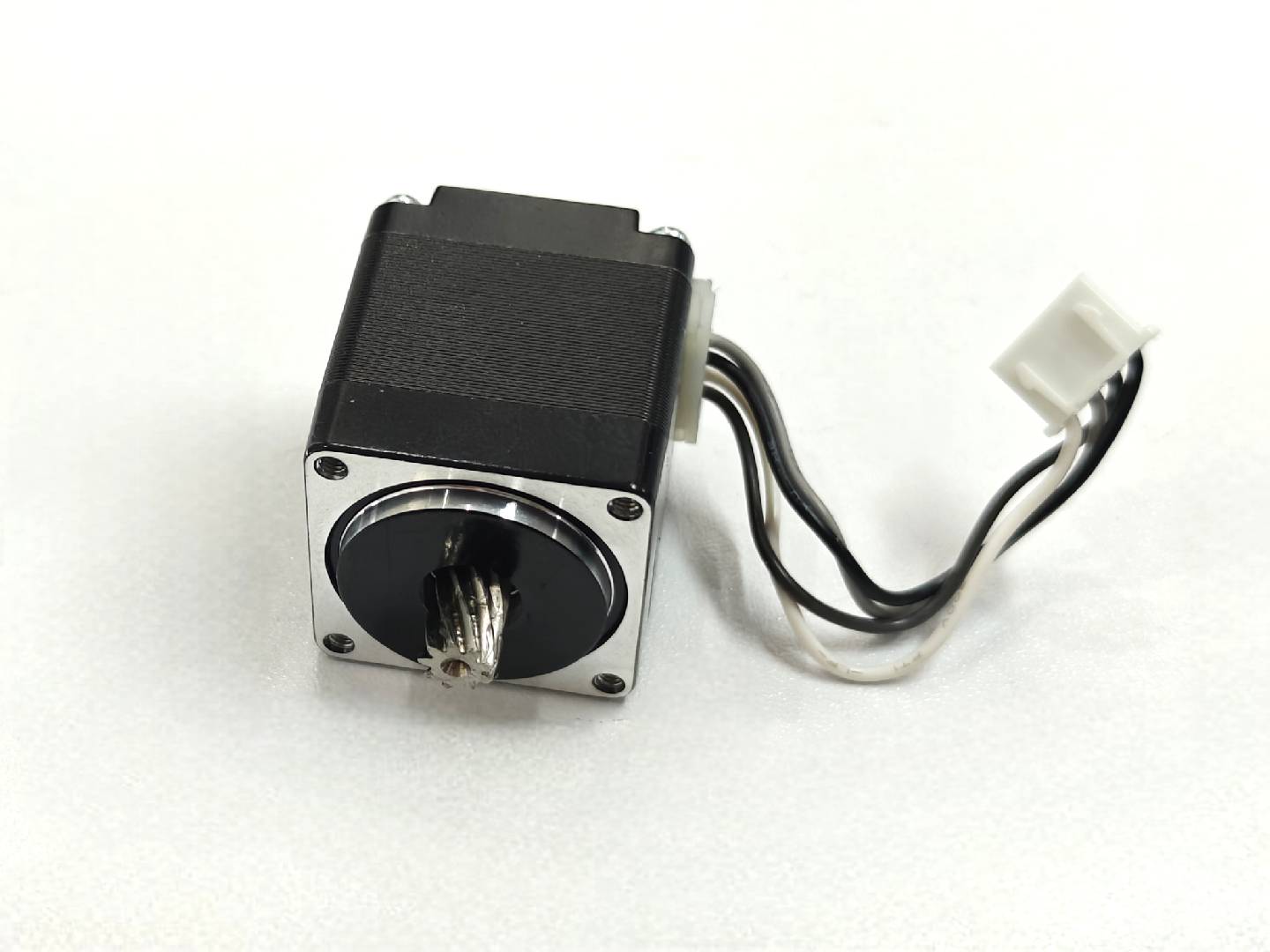
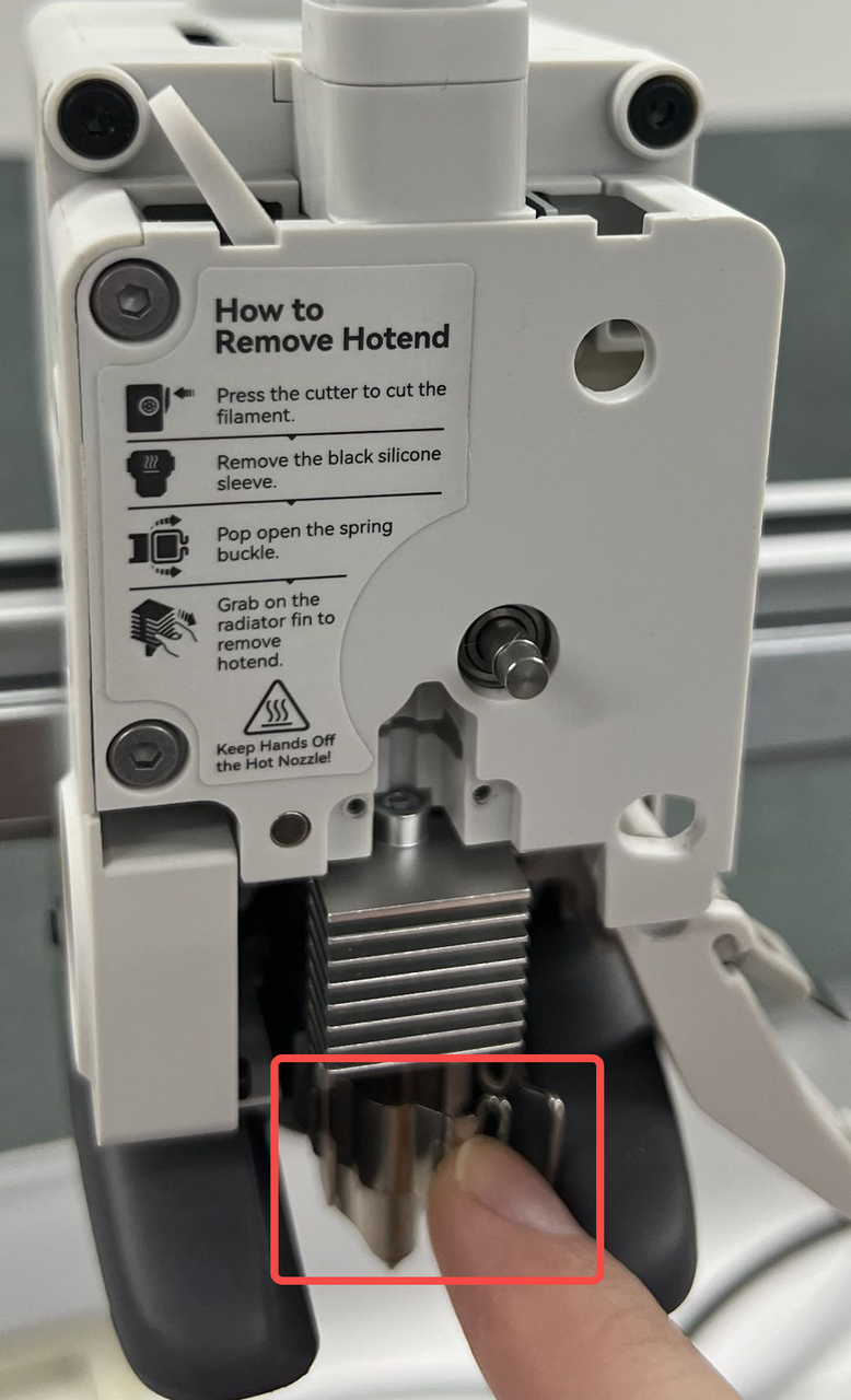
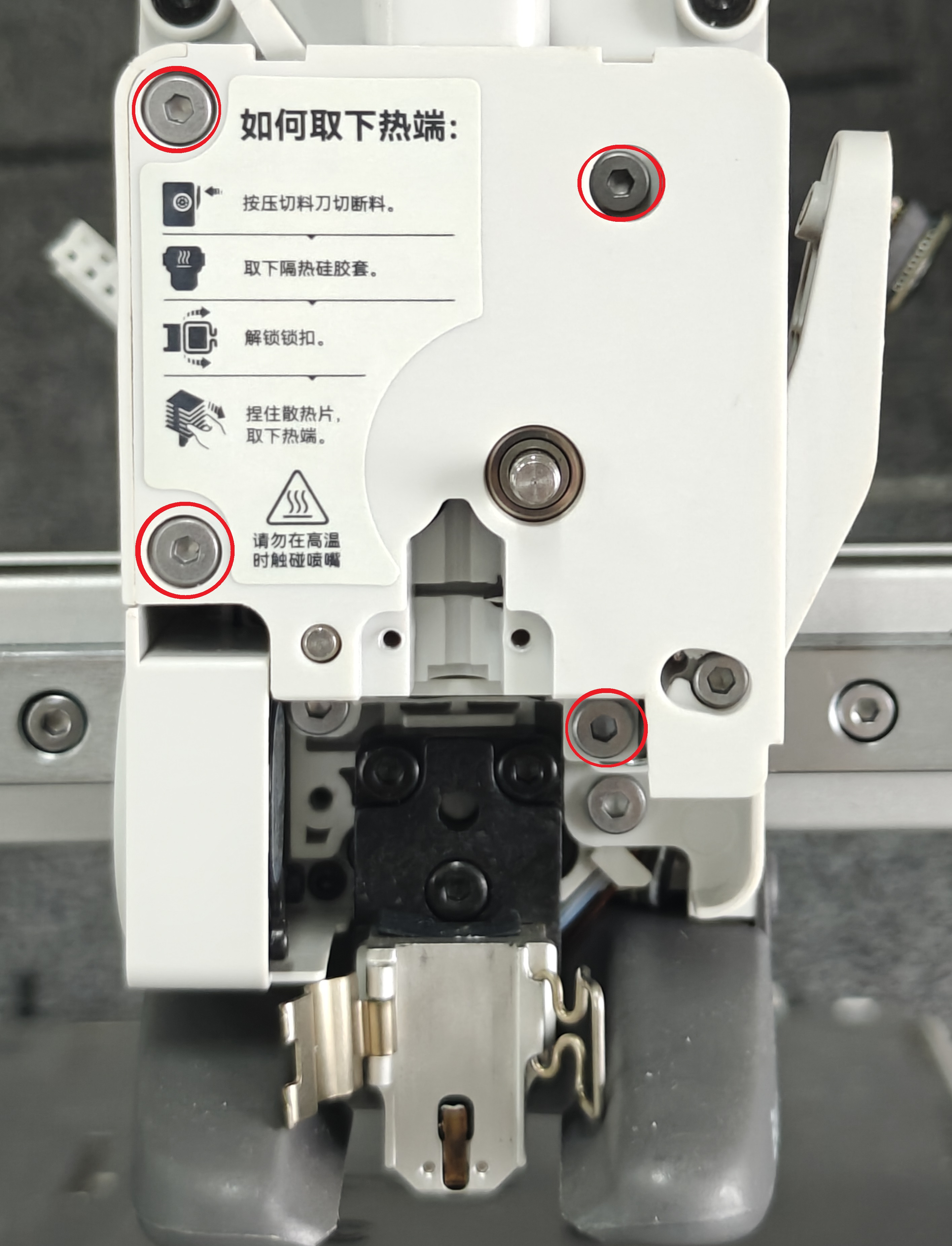
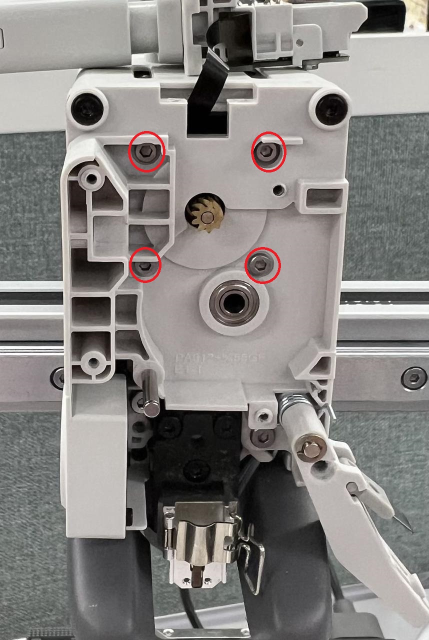
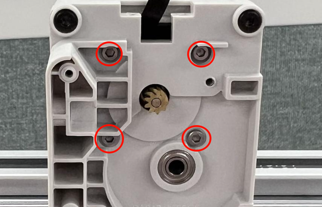
¶ 13.Remove the extruder motor
Remove the four fixing screws of the front motor. At this point, the motor can be removed from the back.
¶ Install the new extruder motor
¶ 1.Fix the extruder motor
First, the motor needs to be inserted from the back of the toolhead. Use 4 M2.5*5 screws from the front to fix the motor.
Note: Ensure the position where the motor cable exits is facing upward.
 |
 |
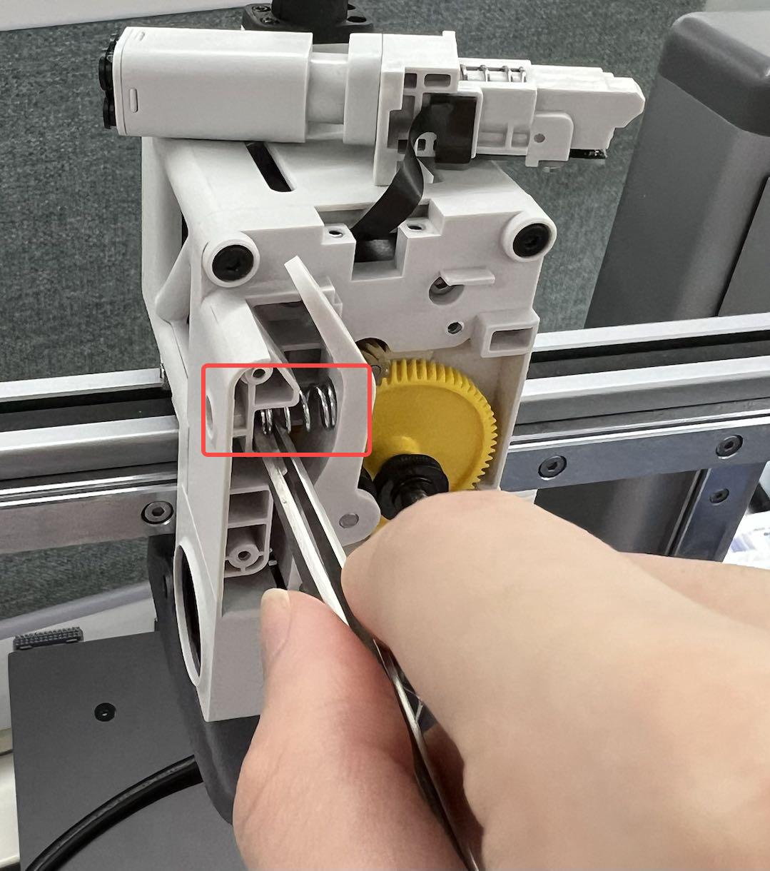
¶ 2. Install the Extruder Gear
First, install the yellow gear into the bearing. Then install the driven wheel bracket. At the same time, hold the washer and spring, and screw in the screw.
Note: The side screws are of M3*11 type. At this time, they do not need to be fully tightened; otherwise, it will be difficult to install the front cover properly.
 |
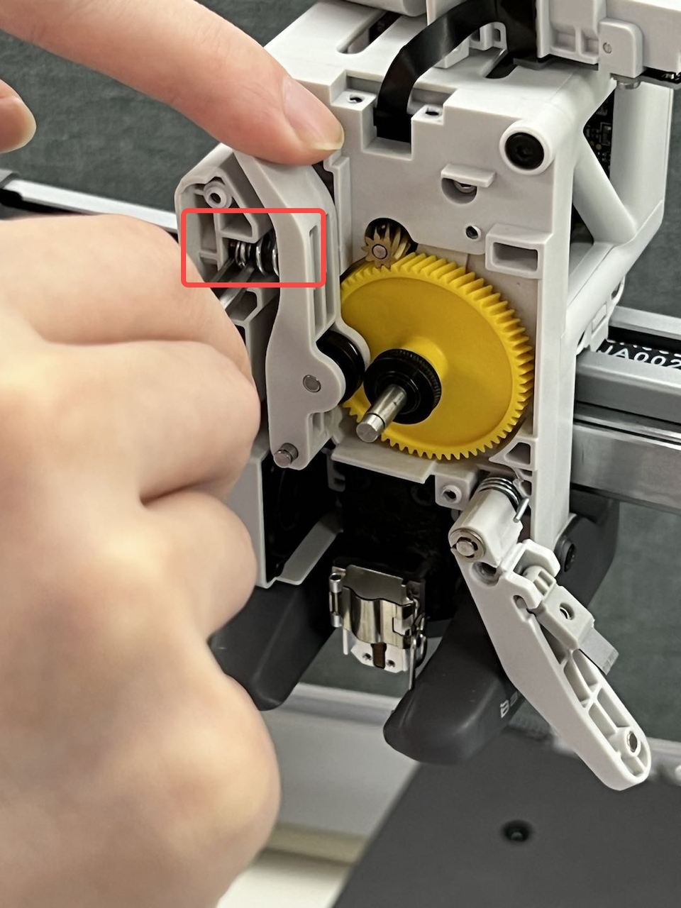 |
Note: Please ensure that the springs and gaskets are correctly installed; otherwise, the extruder may fail to bite the filament, resulting in abnormal extrusion.
 |
 |
¶ 3.Install the front cover of the extruder
Install 4 fixing screws on the front cover and lock the side screws.
Note:The model of the four screws for the front cover is BT2.3*7.
 |
 |
¶ 4.Install the filament hub assembly
Install the filament hub assembly, make sure that the black FPC cable is not folded and smoothly placed in the vacant position. Then, tighten the 2 screws to secure the filament hub in place.
Note:The two screws for the filament hub assembly are of model BT2.6*5.
 |
 |
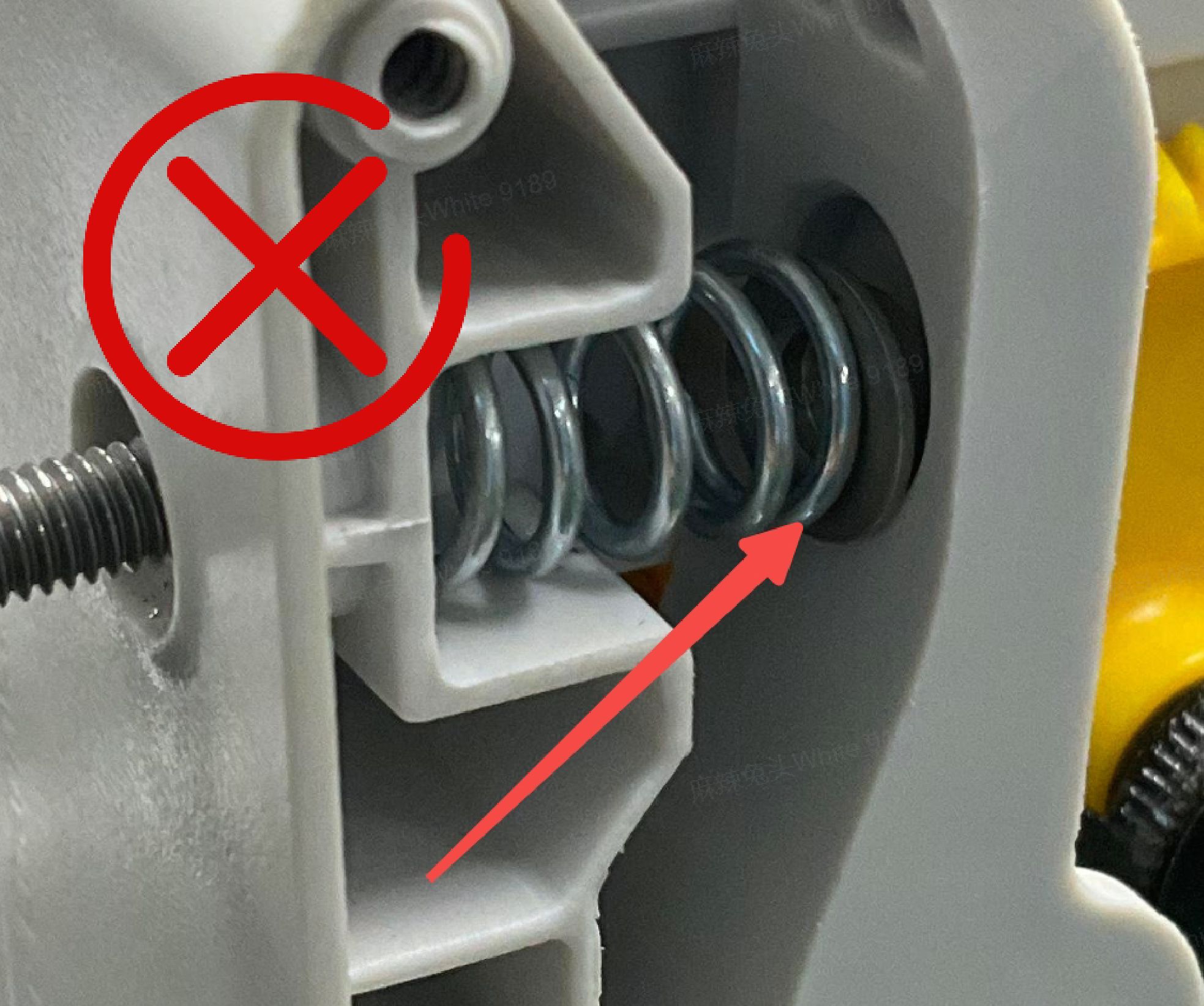
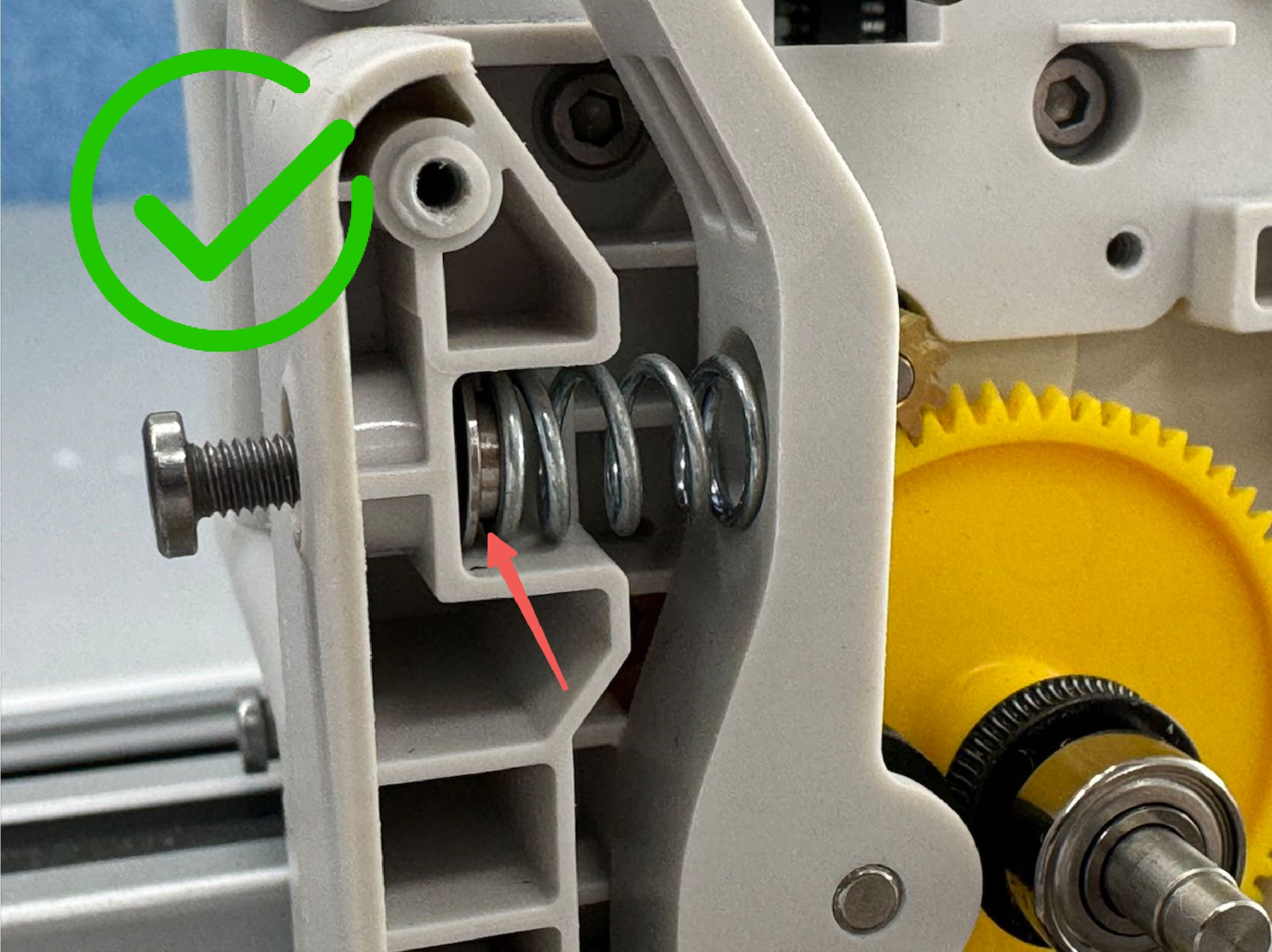
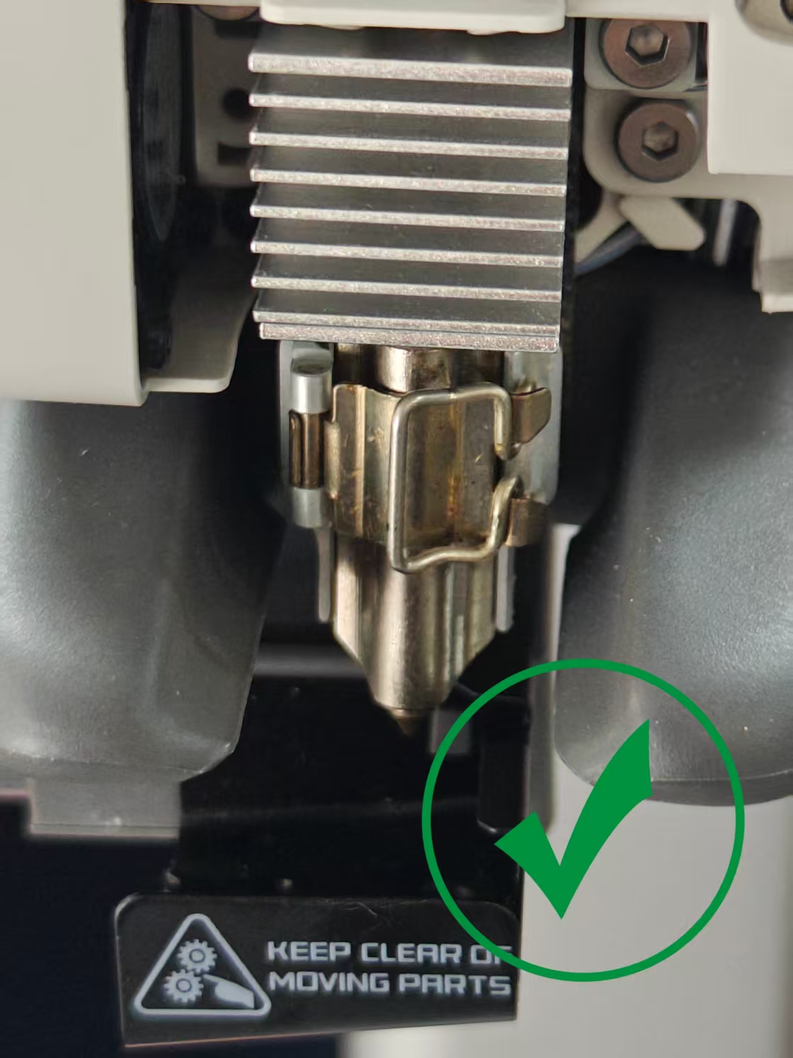
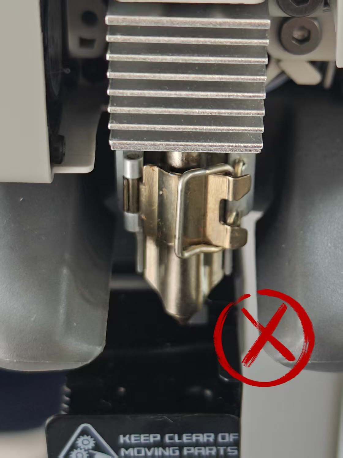
¶ 5.Install the nozzle assembly and the silicone sock for hotend
Then, install the nozzle assembly onto the hotend heating assembly, lock it with the snap-fit, and install the silicone sock for hotend.
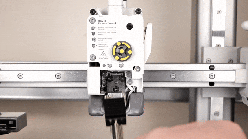
After the nozzle assembly is installed, pay attention to checking whether the installation is correct.
| Proper installation method | Incorrect installation method |
 |
 |
¶ 6.Lock the filament cutter lever in place
First, align the blade with the extruder hole where the blade will slide into.
Next, push on the filament cutter lever and hold it in place while you re-install the screw.
Make sure not to overtighten the screw, to avoid damaging the plastic threads.
 |
 |
¶ 7.Install the toolhead front cover
The toolhead front cover can now be re-installed. Simply attach it on the top of the toolhead by aligning the clips, then gently push on the bottom side.
You will hear the clips when the installation is complete.
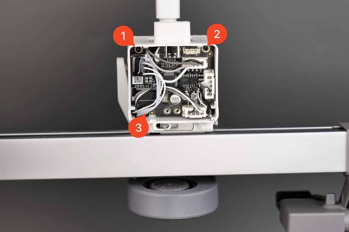
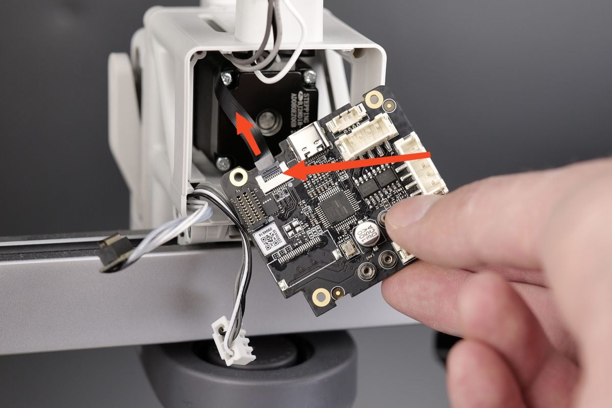
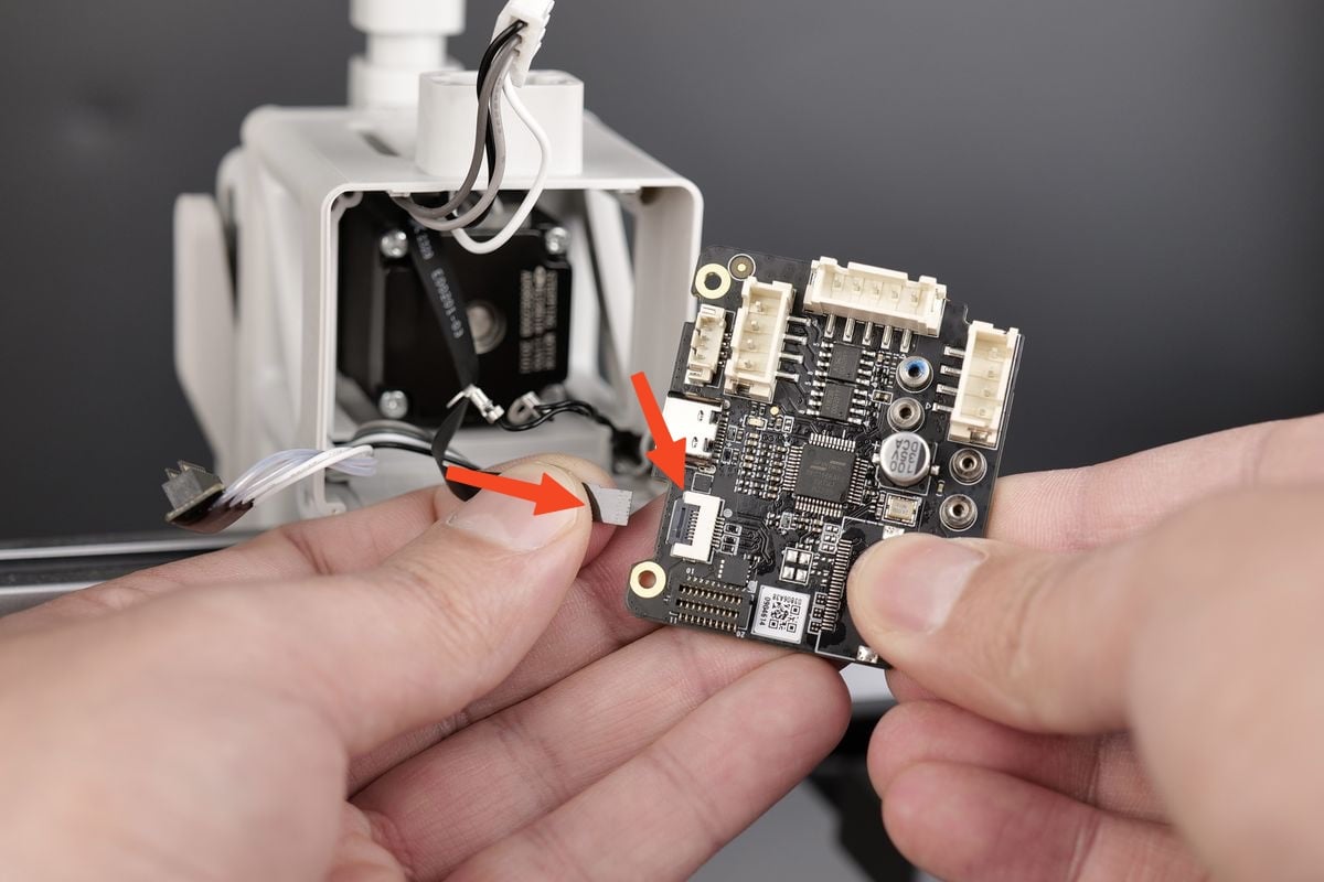
¶ 8.Attach the TH Board to the housing
Open the clip on the TH board for the ribbon cable. Then, gently push the cable in the connector, and close the clip.
Carefully route the Extruder Motor cable next to the ribbon cable as shown in the image below.
After this step is done, you can gently push the TH Board back in its position.
 |
 |
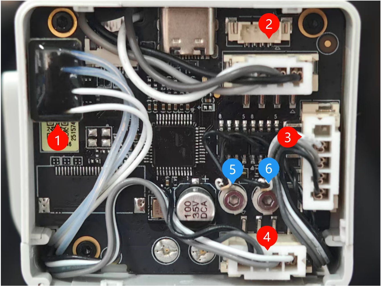
Use the three black screws to re-attach the TH Board back to the print head.
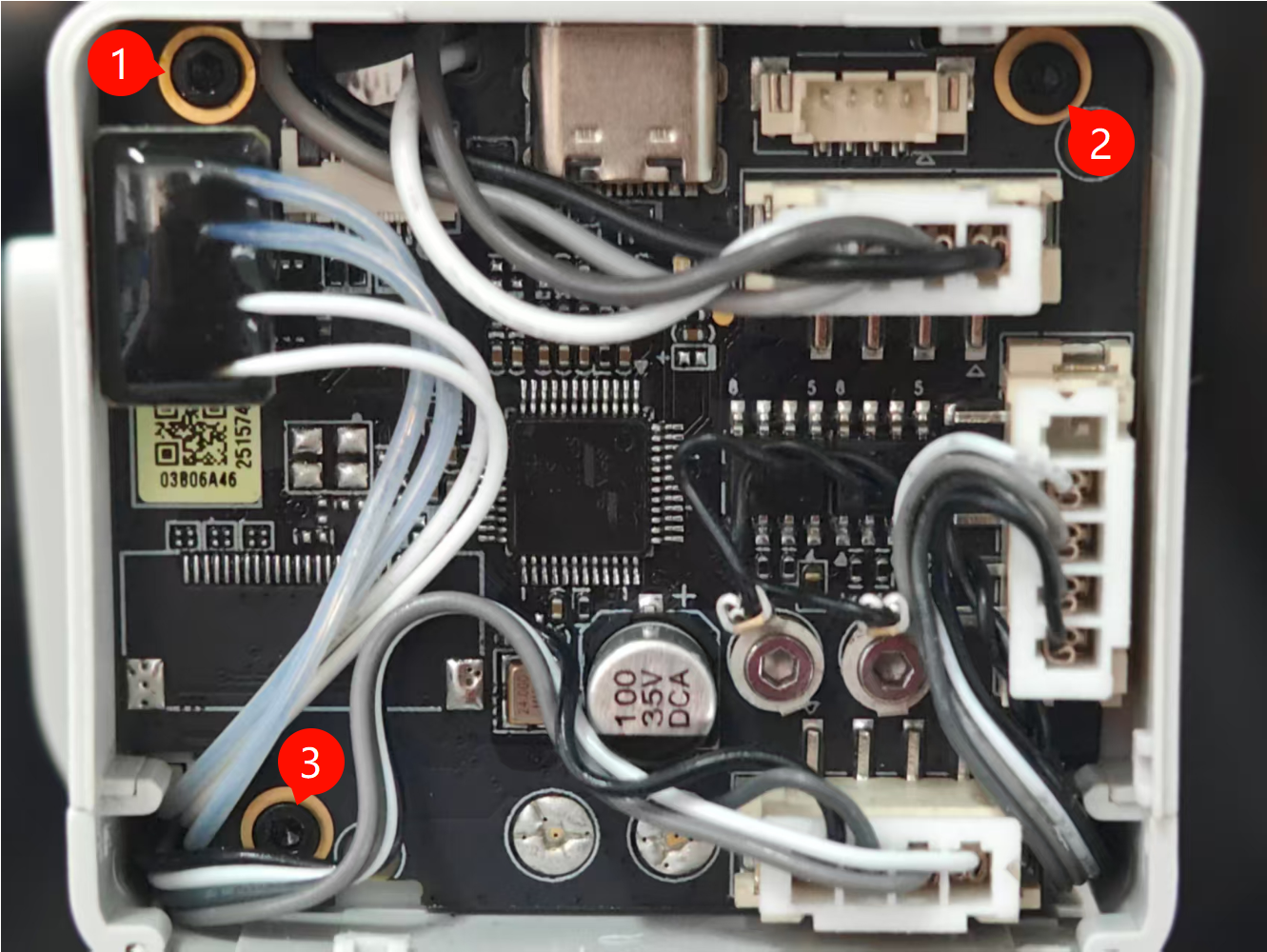
With the new TH Board back in its original position, you can re-connect all the cables as shown below.
- Hotend Heating Assembly
- Extruder Motor
- Hotend Cooling Fan
- Part Cooling Fan
- Eddy current coil
- Eddy current coil
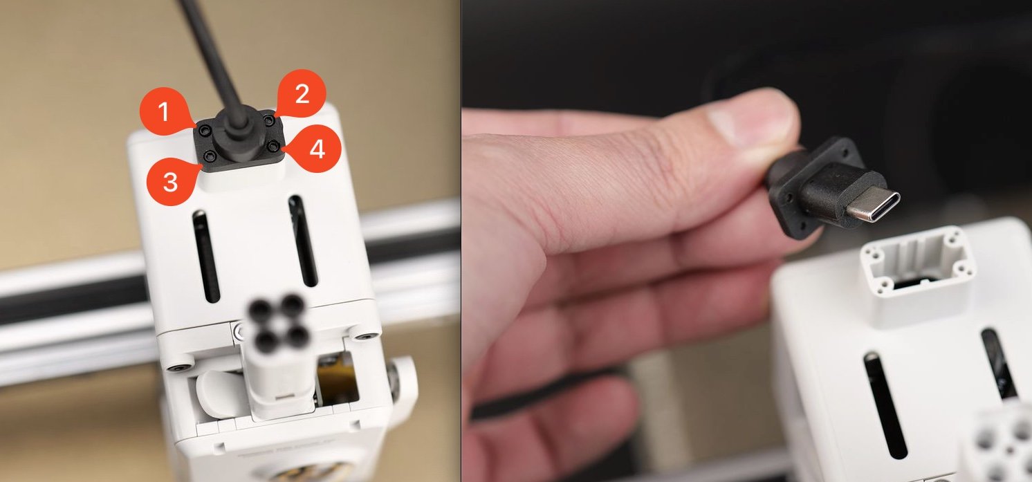
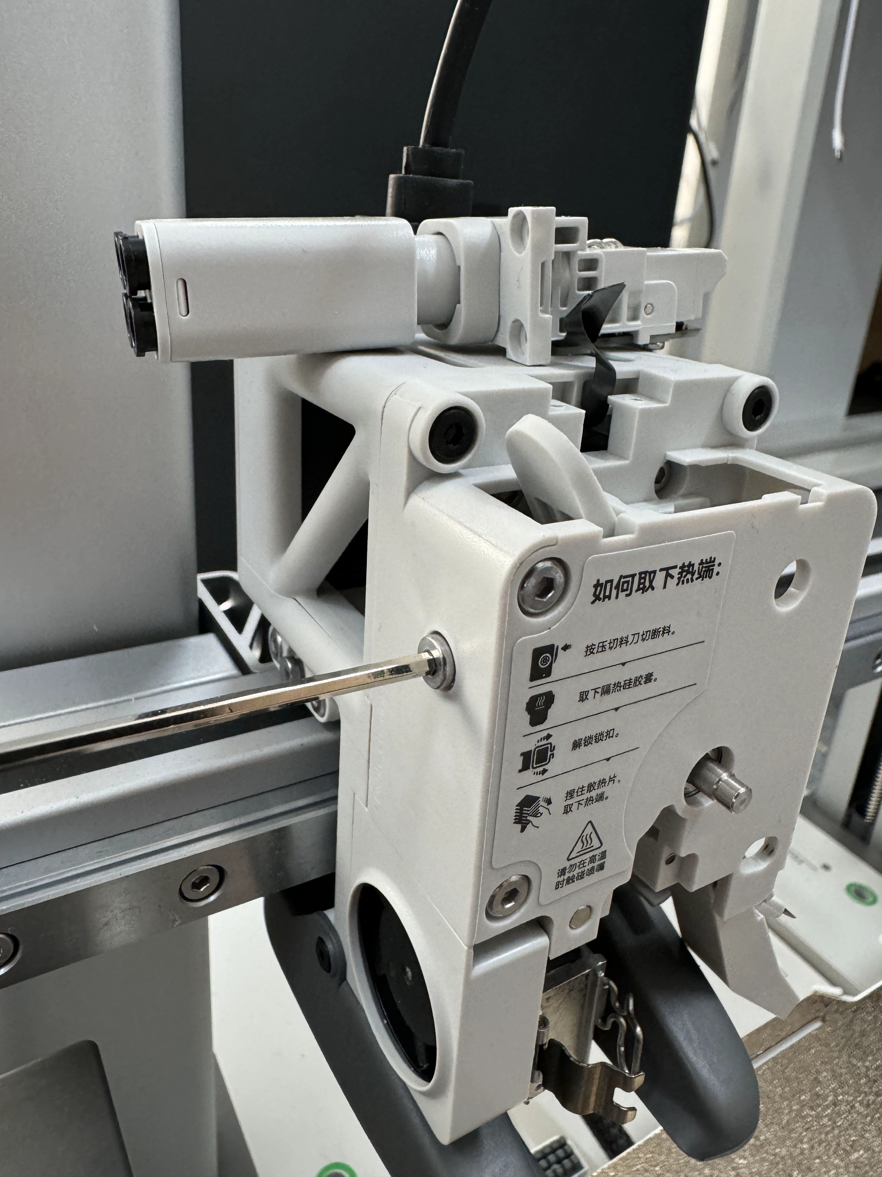
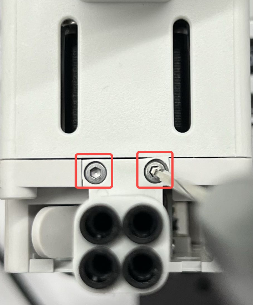
¶ 9.Re-connect the USB-C cable
Re-install the USB-C cable using the four screws we removed in the first step, while being careful about the orientation.
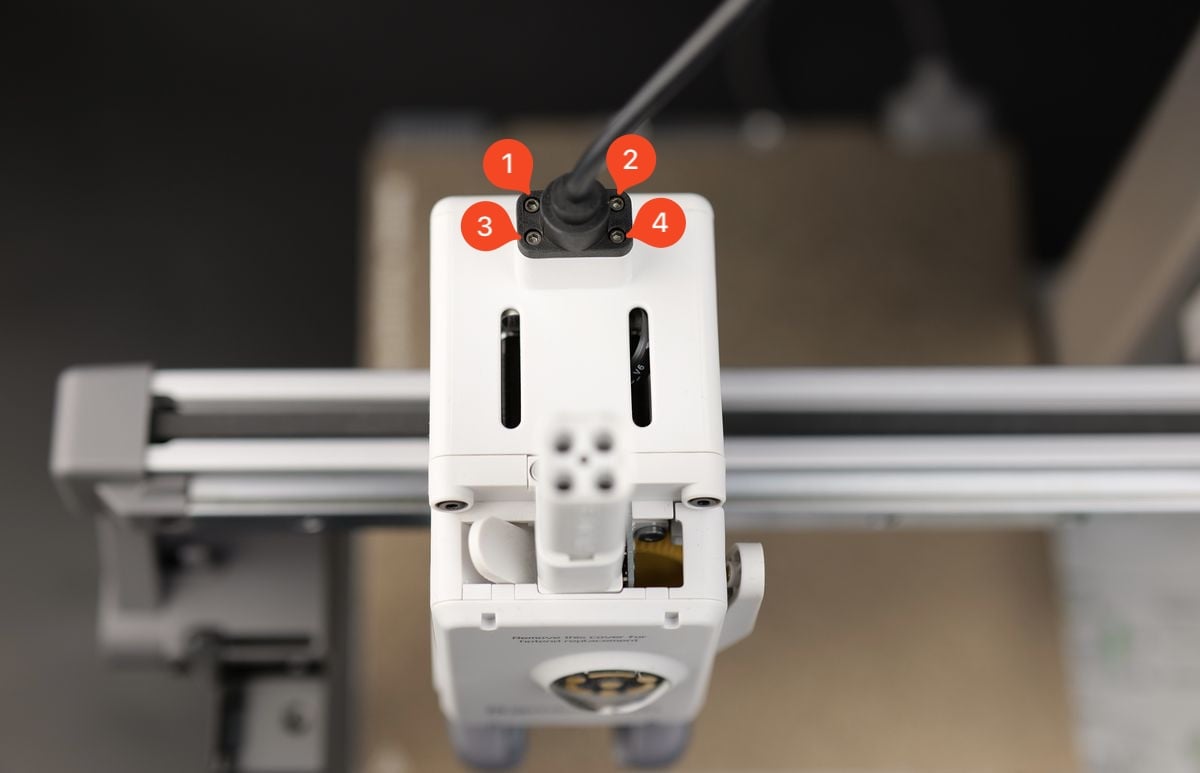
Important!
Do not over-tighten these screws, as the threads can damage the plastic.
Take note of the USB-C cable orientation and the small groove from the back that aligns it.
The USB-C cable only fits in one position, with the correct orientation having the line in the cable connector aligned to the back of the printer and toolhead.
¶ 10.Install the toolhead rear cover
Finally, install the toolhead rear cover.
The rear cover clips in place. Simply align the two brackets on the rear cover towards the top, then push it until you hear a few clicks.
¶ Verify the functionality
Turn on the printer and start a filament loading procedure.
If the operation is successful, you will be able to see the plastic being extruded from the nozzle assembly.
¶ Calibration step after the operation
It is suggested that you conduct a comprehensive calibration after replacing the extruder motor to ensure smooth operation of the printer.
Additionally, it's strongly advised to wash the PEI textured plate before use, as it may have been contaminated during this process.
¶ Potential problems and solutions
If you encounter problems during the installation of a new Extruder motor, please check the potential problems and solutions listed below:
¶ The hotend temperature is 0
Check the Hotend Heating Assembly connector and confirm it is correctly inserted, as shown in installation Step 8 Re-connect all the cables.
It is important to carefully align the connector pins to the Toolhead Board.
If the issue persists, the thermistor wires might have been damaged (white wires)
¶ The hotend cannot be heated
Check the Hotend Heating Assembly connector and confirm it is correctly inserted, as shown in installation Step 8 Re-connect all the cables
It is important to carefully align the connector pins to the Toolhead Board.
If the issue persists, the heater wires might have been damaged (Translucent wires)
¶ Printer is not homing correctly
Check the Eddy Sensor wires (5 and 6) and confirm they are correctly installed on the back of the Toolhead Board, as shown in installation Step 8 Re-connect all the cables
¶ Filament sensor is not working
Check the Ribbon Cable and confirm it is correctly installed on the back of the Toolhead Board, as shown in installation Step 8 Attach the Toolhead Board to the housing
If the ribbon cable is damaged, you will need to replace the Filament Sensor.
¶ End Notes
We hope the detailed guide provided has been helpful and informative.
If this guide does not solve your problem, please submit a technical ticket, we will answer your questions and provide assistance.
If you have any suggestions or feedback on this Wiki, please leave a message in the comment area. Thank you for your support and attention!