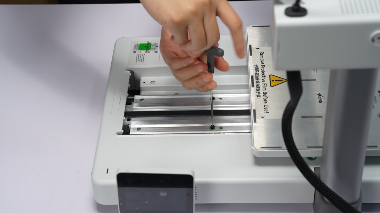
If there are stoppers on the Z-axis of your printer, use the H2.0 hex wrench to unscrew and remove them.
For the latest packaging, other changes may also be applied. Please refer to the one you receive.
Please note that the protective film, foam, and cardboard may differ from what is shown in the unboxing video. For example, the newly shipped A1 has removed the cardboard around the toolhead. Please refer to the machine you actually received for accurate information.
Also, please be aware that the protective film on the surface of the heatbed has been removed. We have discontinued the use of protective film on the heat bed for two reasons:
1. User feedback indicated difficulty in removing the film.
2. Some users forgot to remove the film.
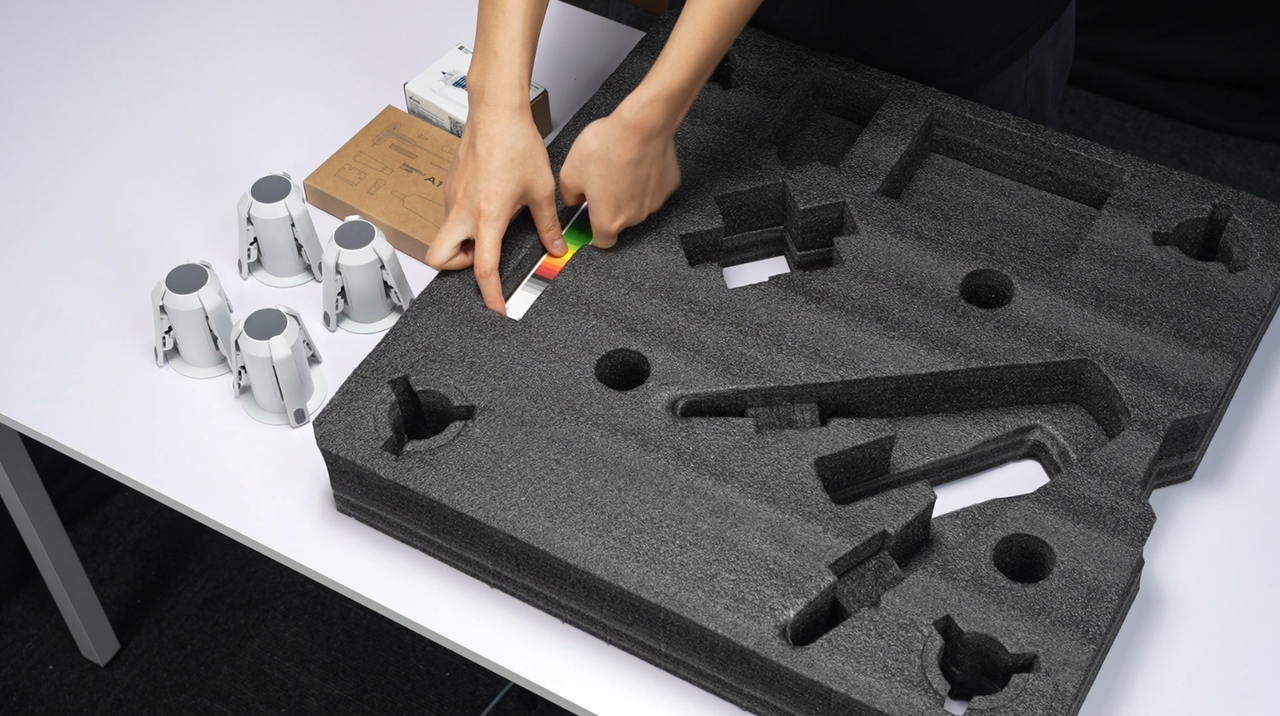
Filament swatches are no longer included in the latest packaging of A1 series.
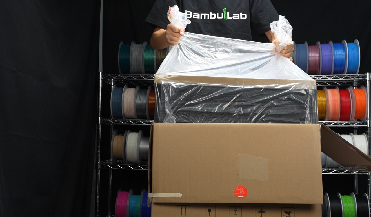
¶ Step 1: Unbox and take out A1, AMS lite, and its accessories.
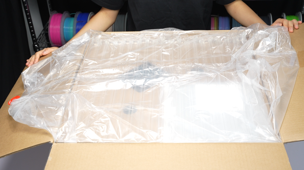
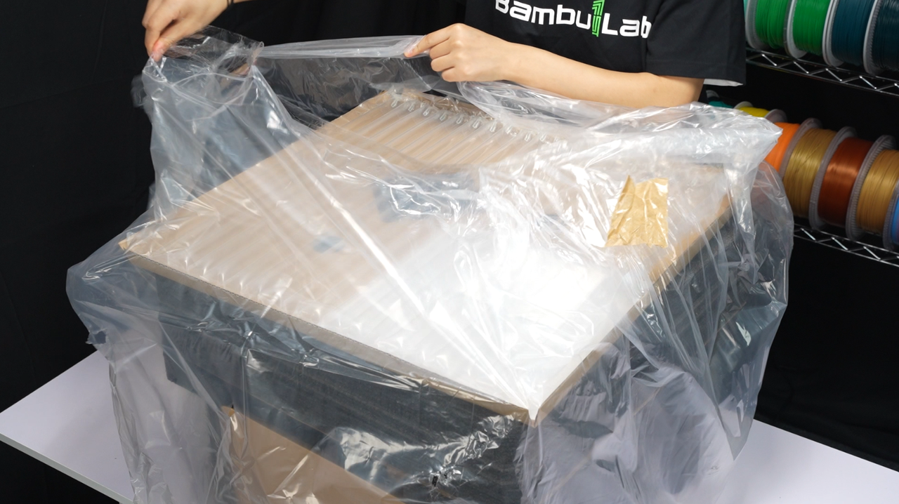
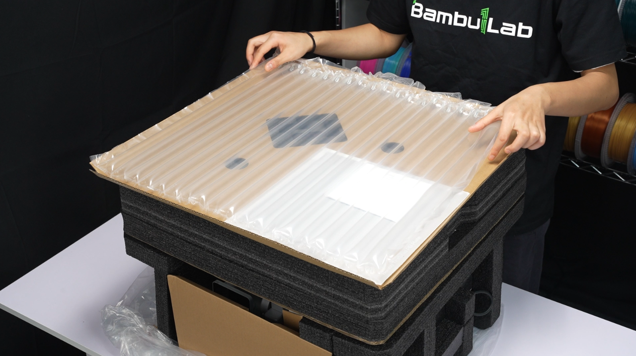
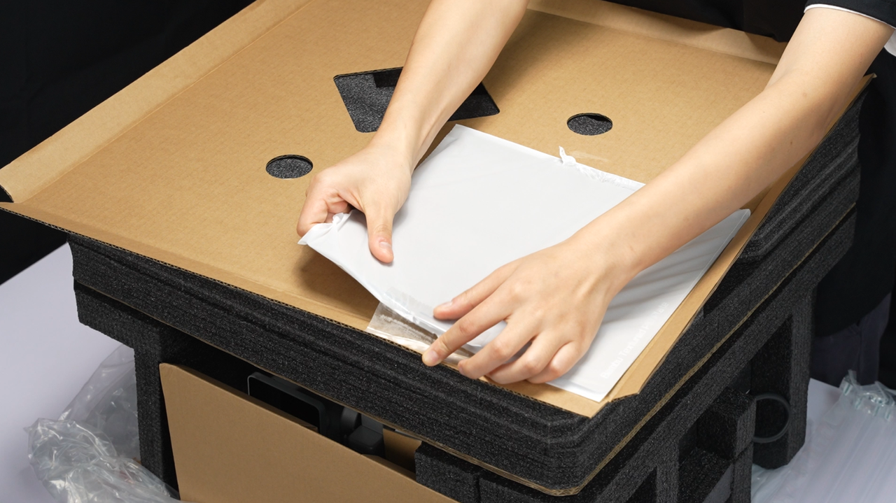
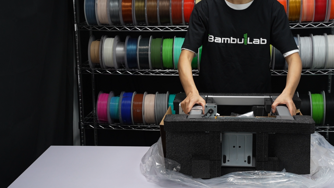
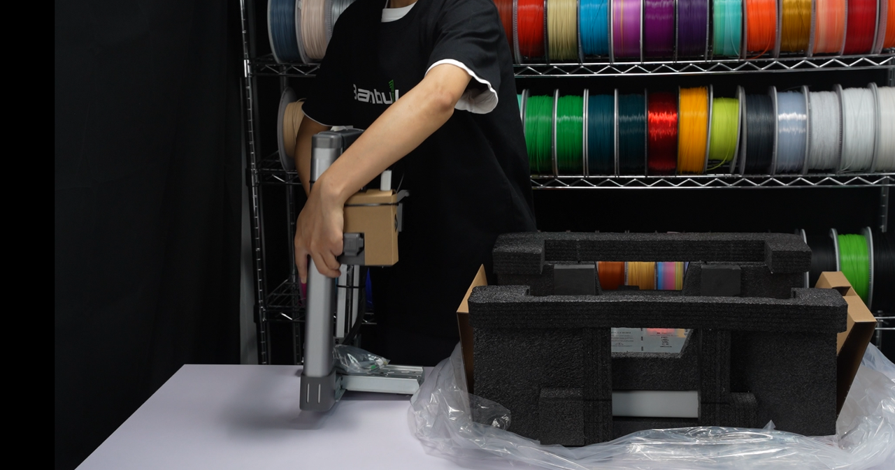
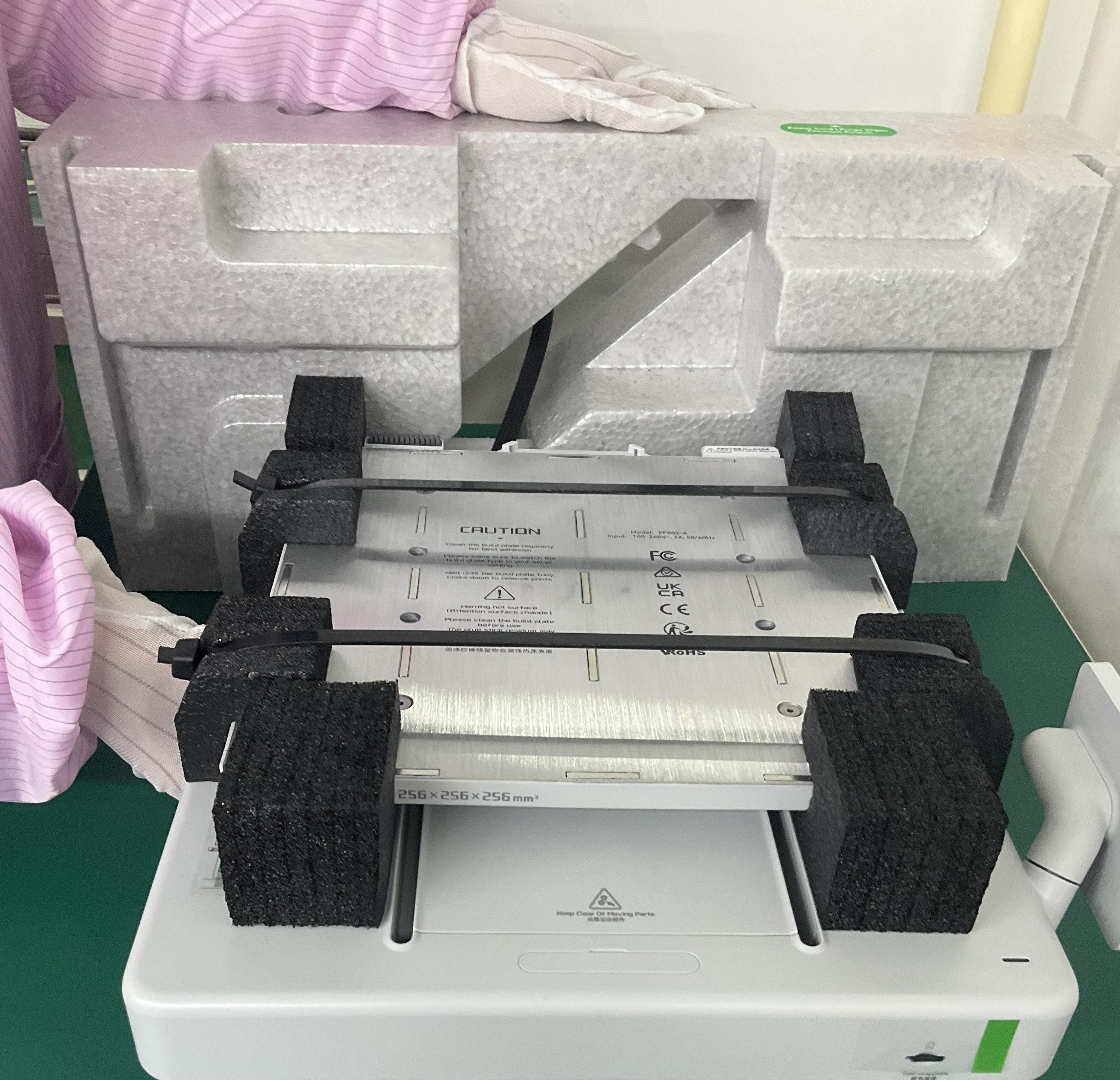
1. Use the handles on both sides of the plastic bag inside the cardboard box to take out the printer from the box. Place the printer on a flat surface and remove the protective foam from its surface.
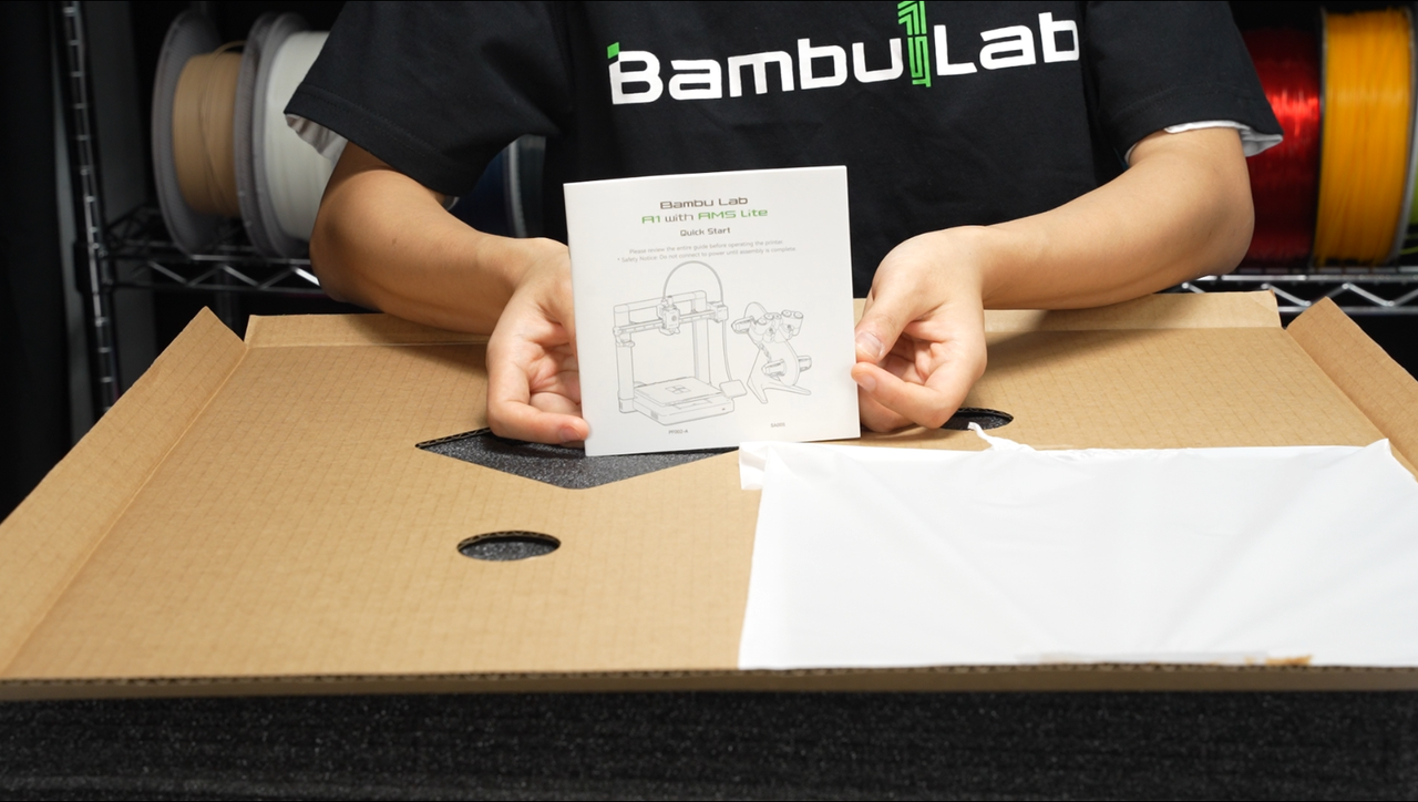
2. Read the quick start guide and familiarize yourself with the precautions for unboxing. Take out the accessories, AMS lite, and the printer.
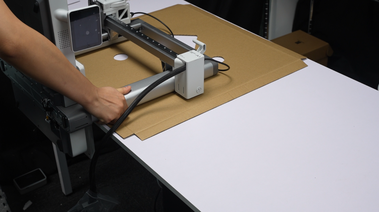
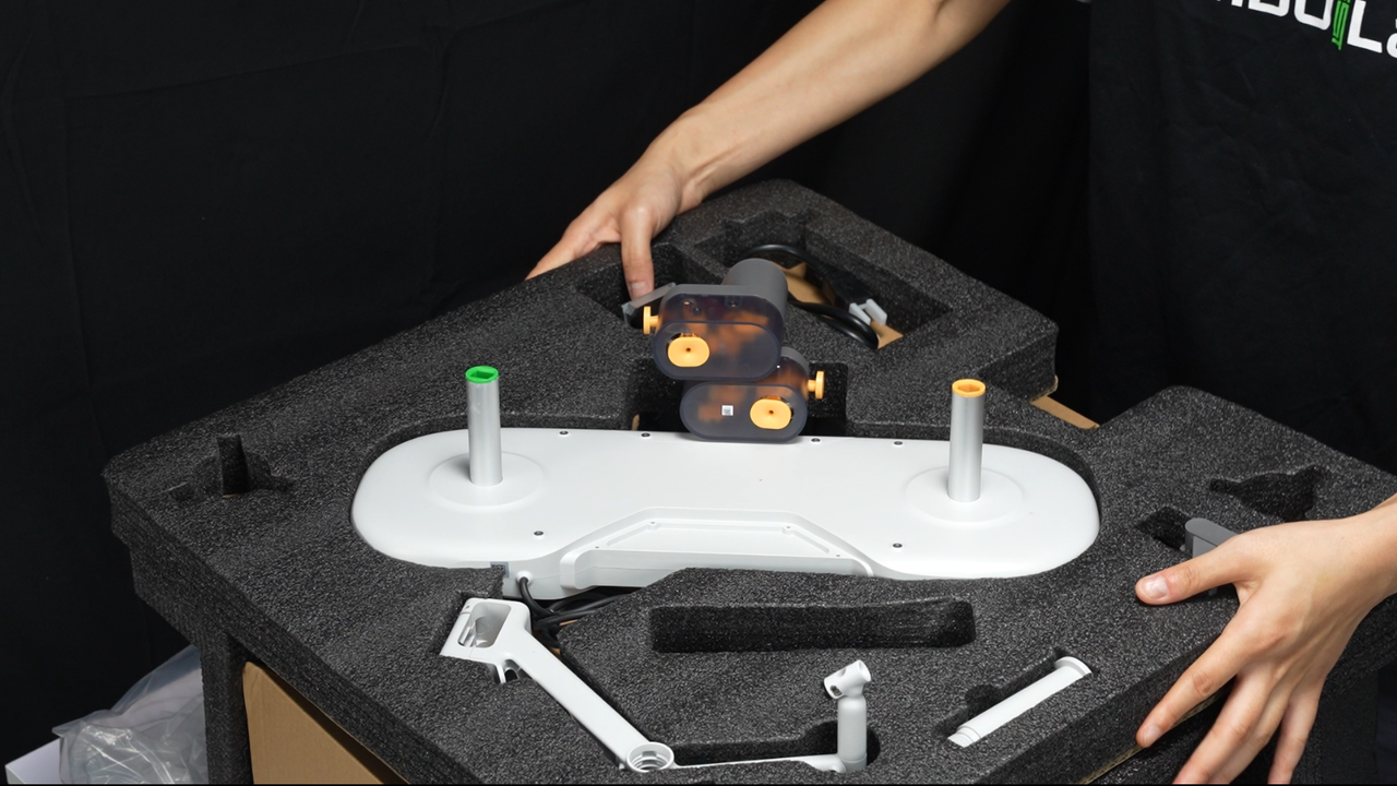
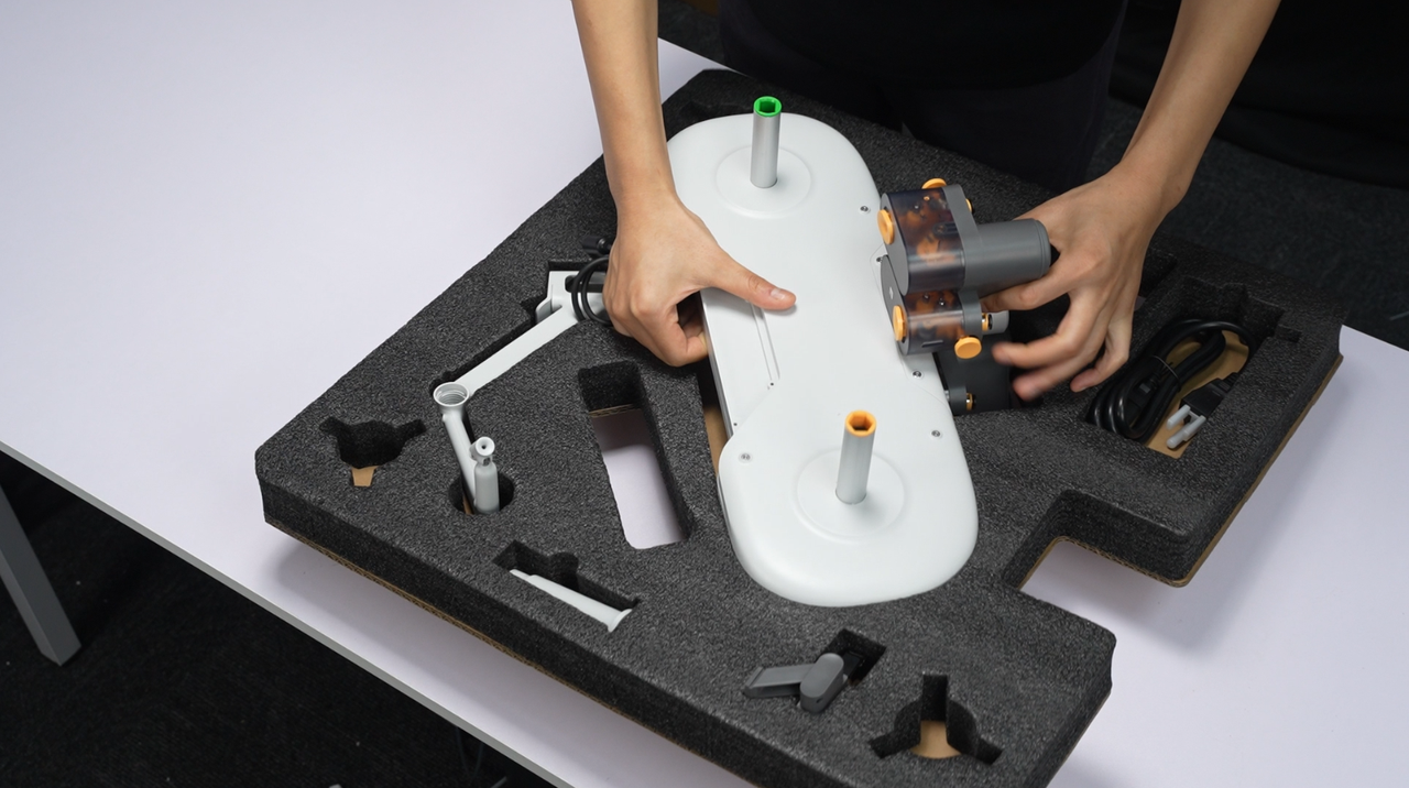
Please do not support the X-axis by hand when removing the printer gantry. Instead, grasp the Z-axis bracket with your hand.
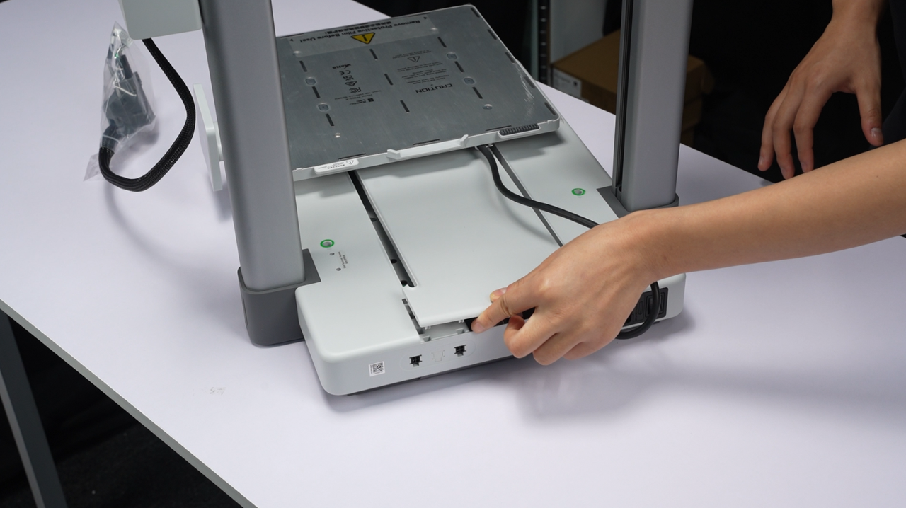
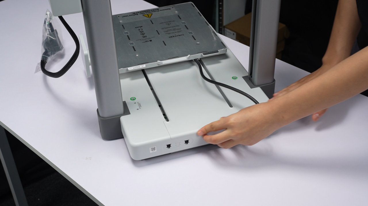
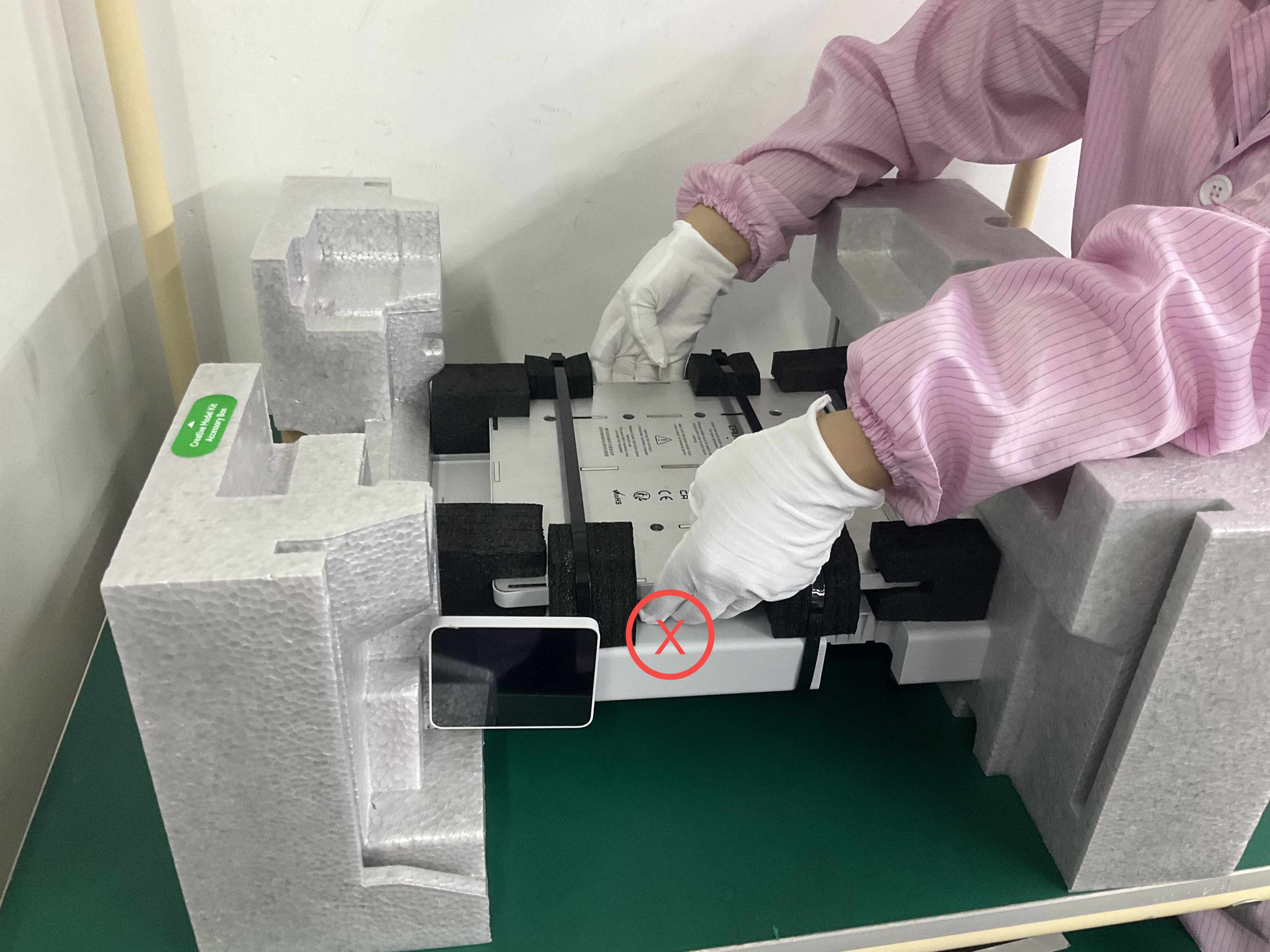
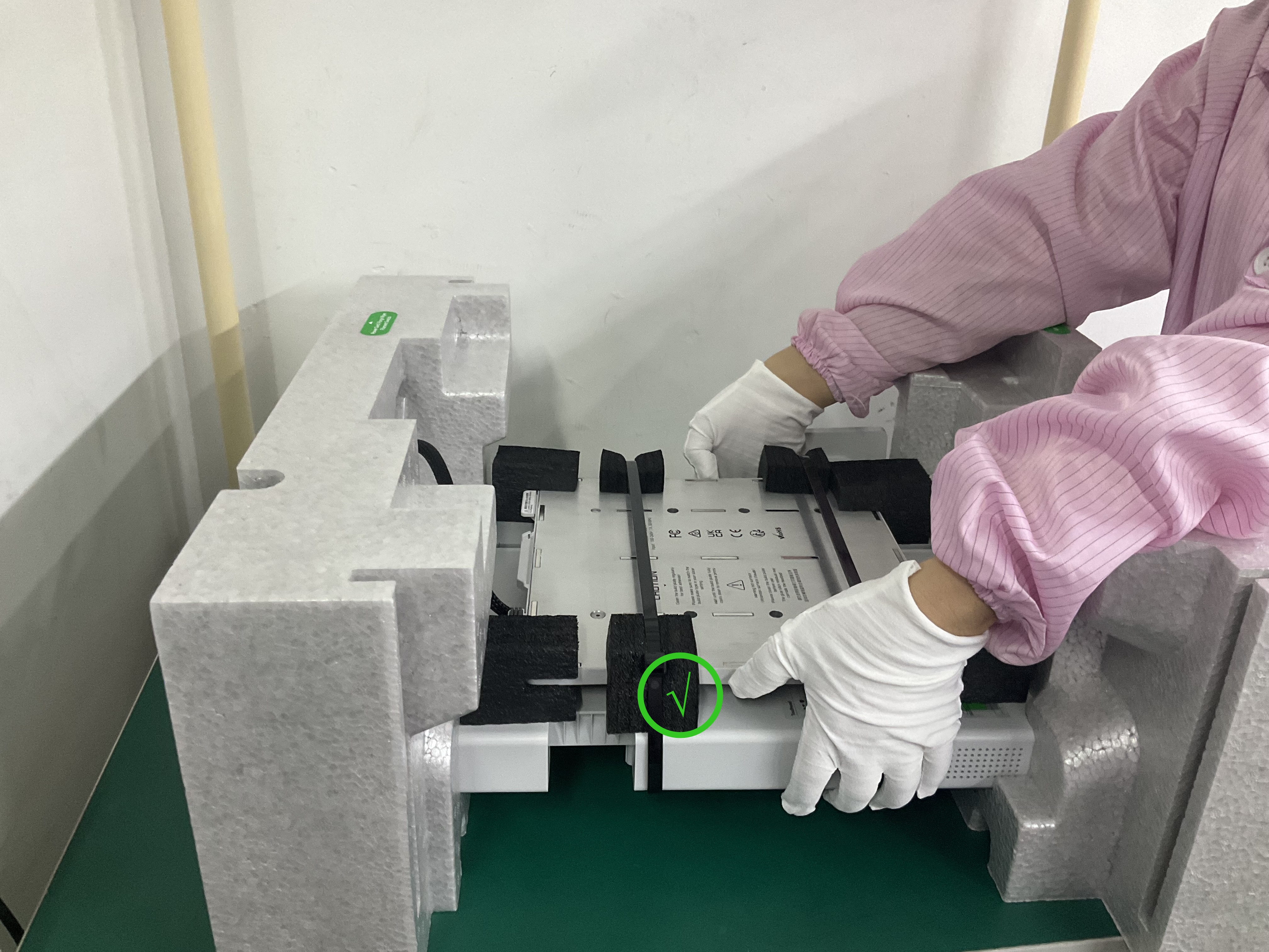
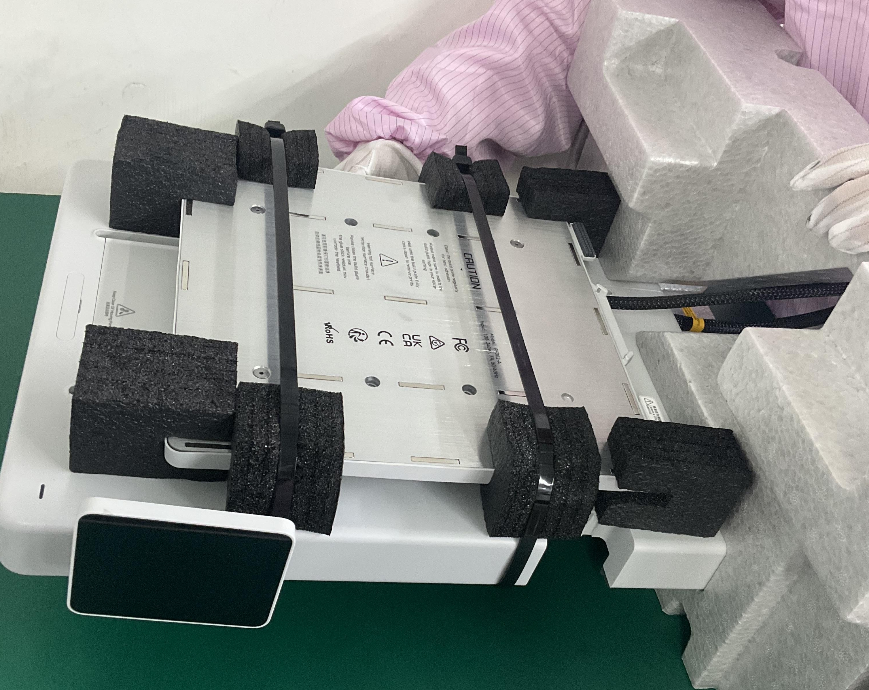
3. When removing the printer base, please do not hold the heatbed by hand. Instead, lift the entire plastic base.
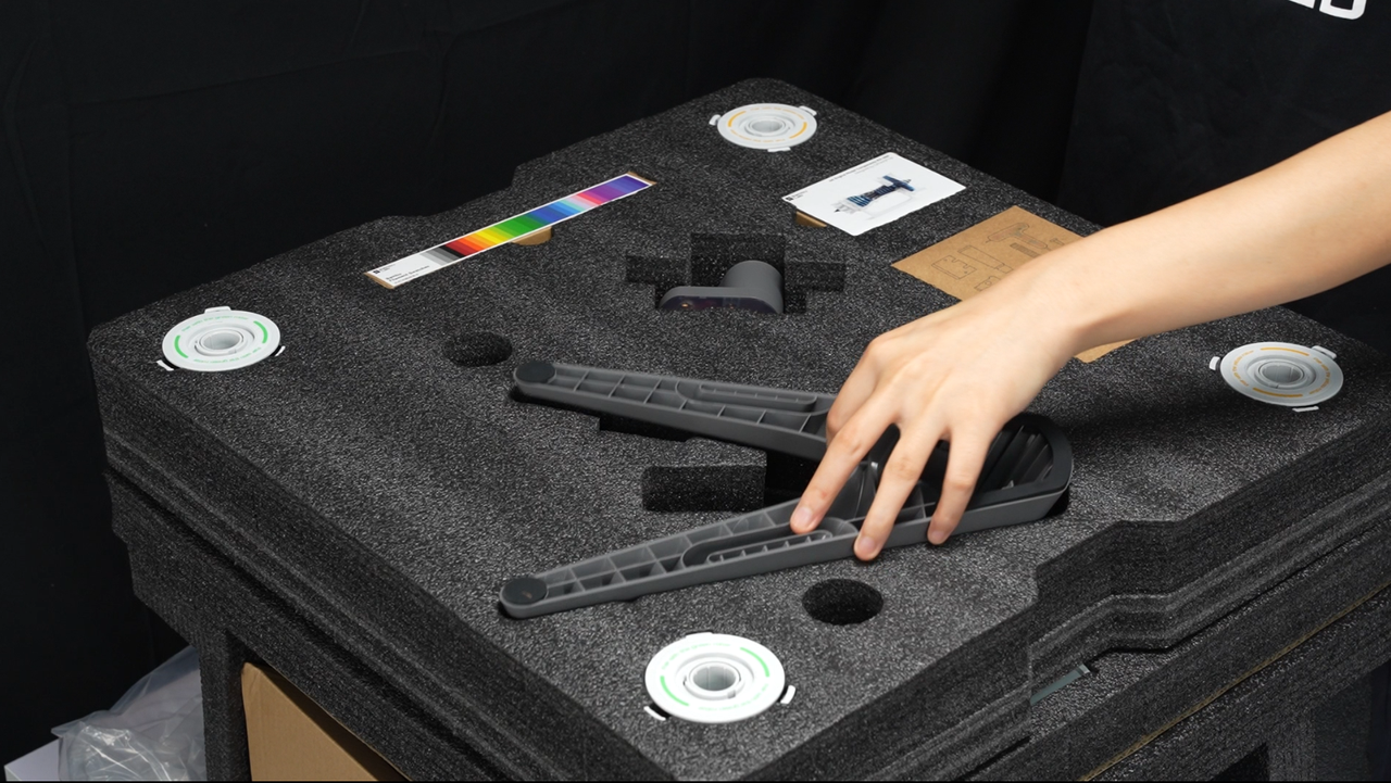
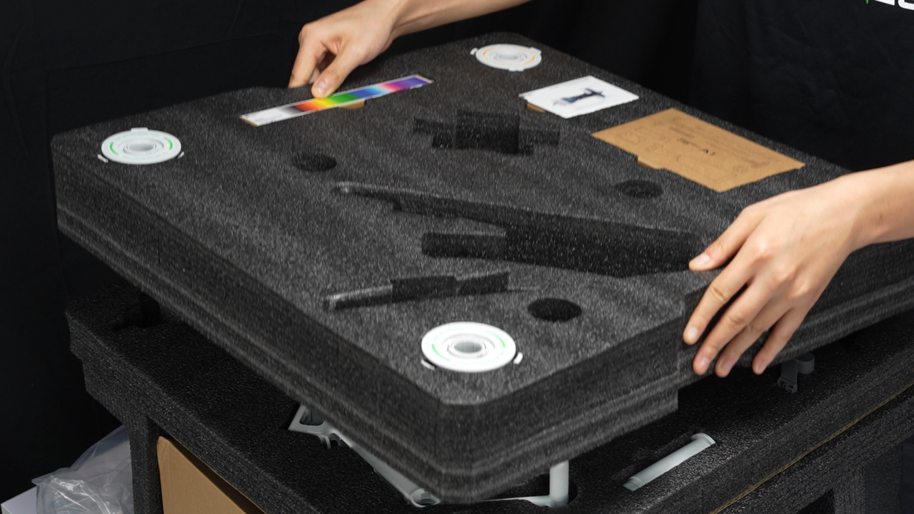
Remove the foam.
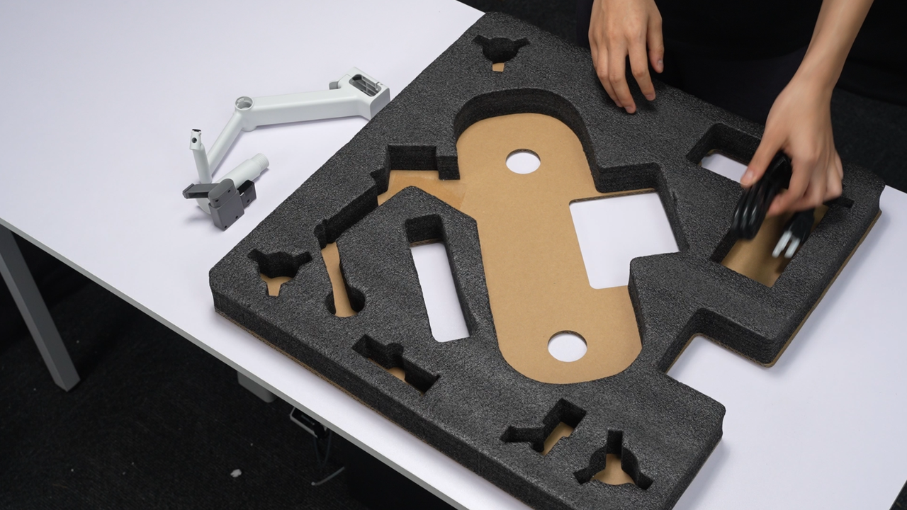
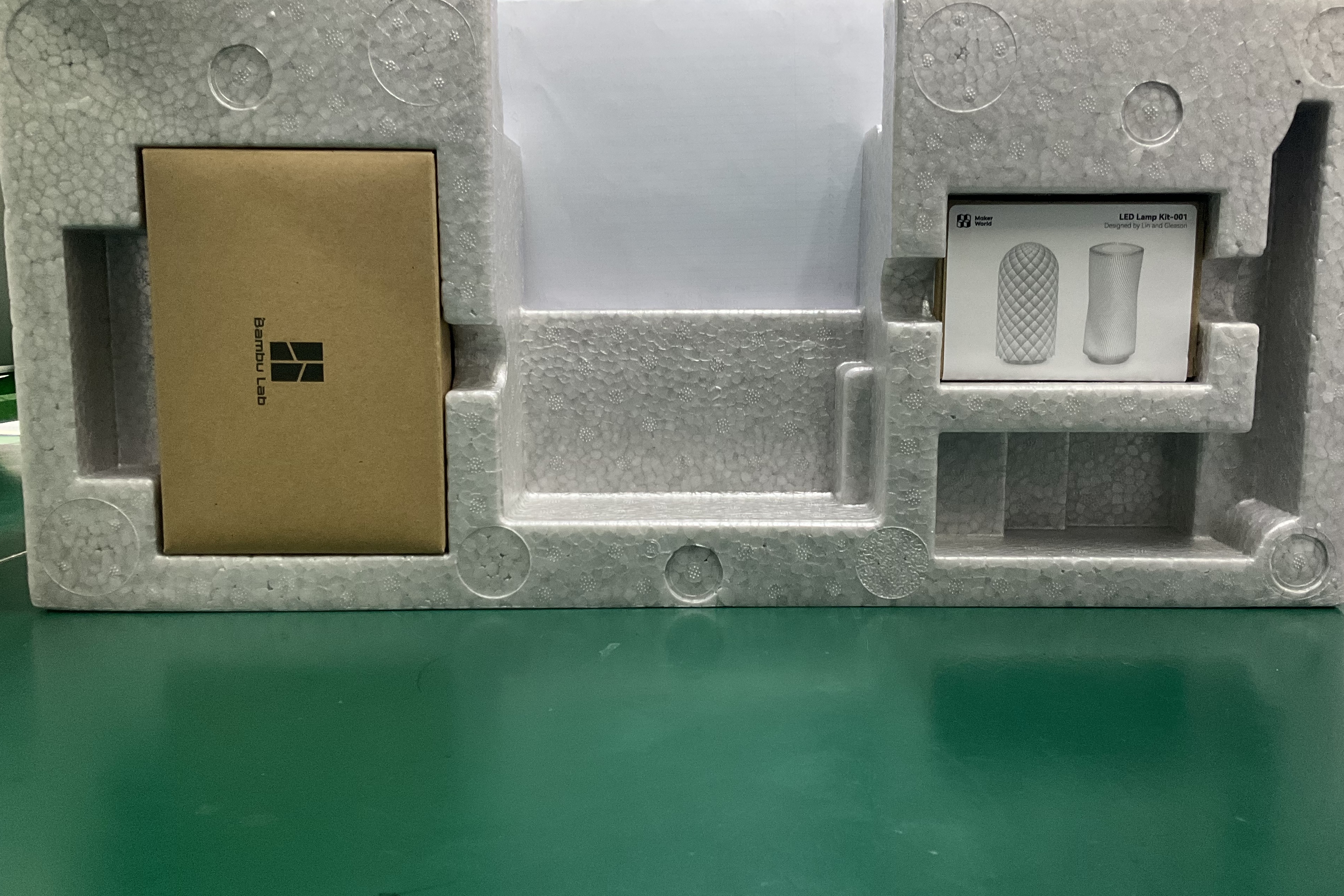
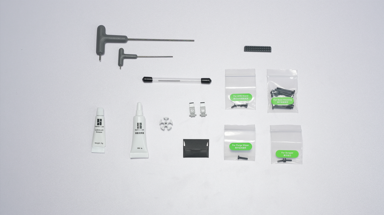
¶ Step 2: Check the accessories in the packaging box.
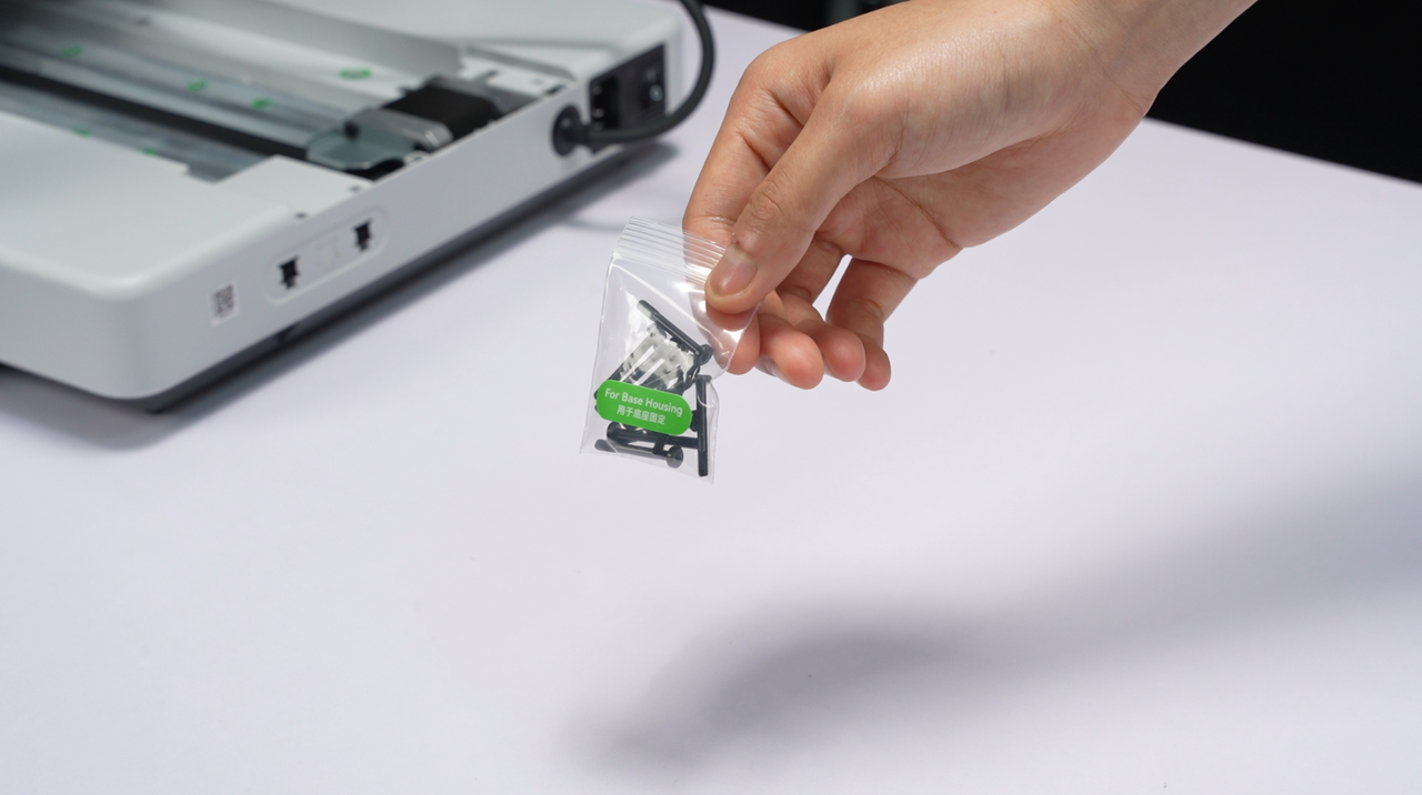
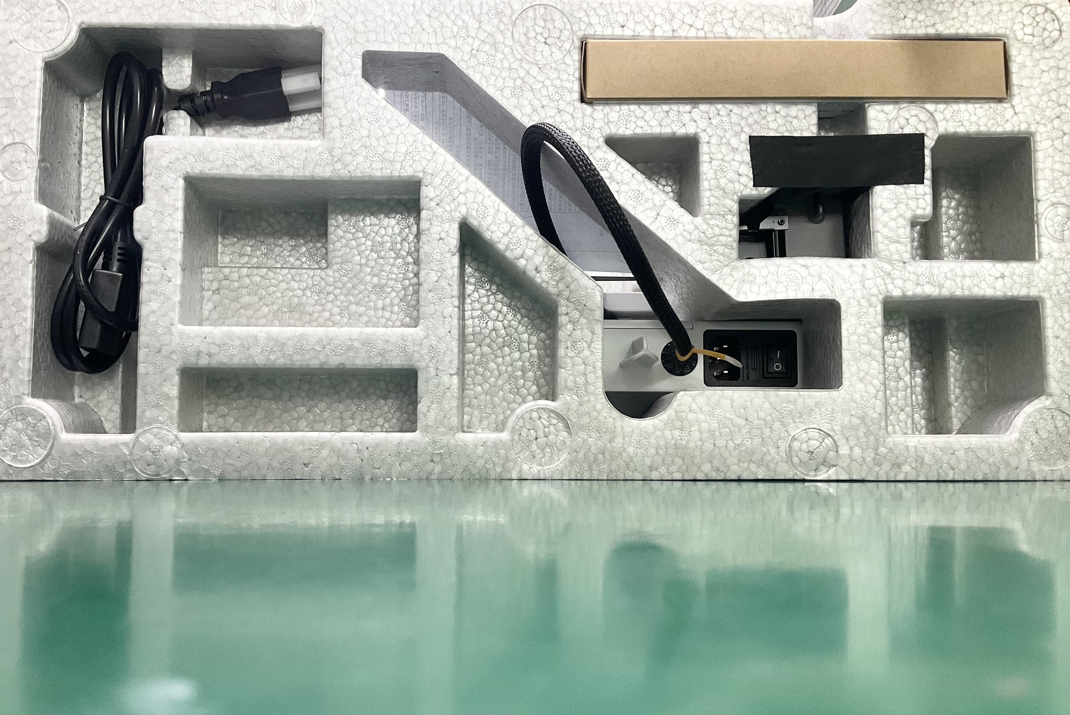
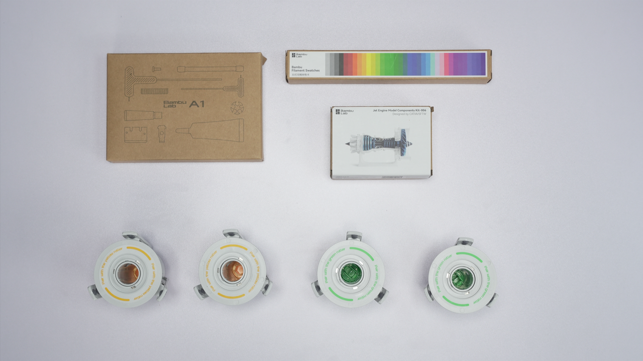
The packaging box includes the following items: A1 printer base housing, A1 printer frame, A1 printer base housing screws (ST3-23 screws for the base), AMS lite body, AMS lite Stand and installation screws (BT3-6 screws for the AMS stand), AMS lite rotary spool holder, Bambu Filament Swatches(Some versions do not include), Purge Wiper and its screws(M3-12 screws for the purge wiper), Spool Holder, PTFE tubes (4 in total, two longer and two shorter, for AMS lite), PTFE tube (1 for external spool holder), Textured PEI Plate, Sample Filament, Unclogging Pin Tool, Allen keys (H2 and H1.5), Heatbed Nozzle Wiper, Cable Organizer, Bambu Scraper Blade and it screws, Spare Filament Cutter, and Lubricant Grease, Lubricant Oil, Quick Start Guide, Warranty Leaflet, Disclaimer, and safety guidelines, 32 GB MicroSD card (inside printer).
In the latest packaging, the items in the accessory box are now placed in transparent plastic bags.
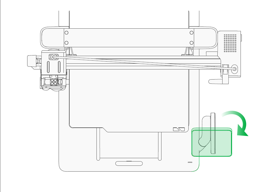
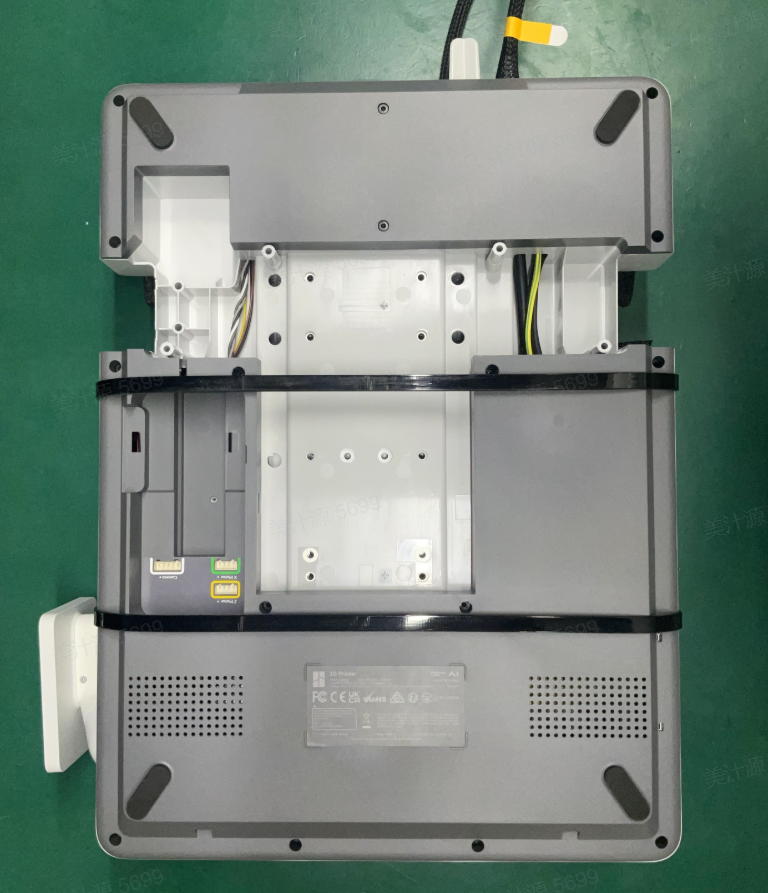
¶ 1. Flip the base housing 90 degrees to the side opposite to the screen.
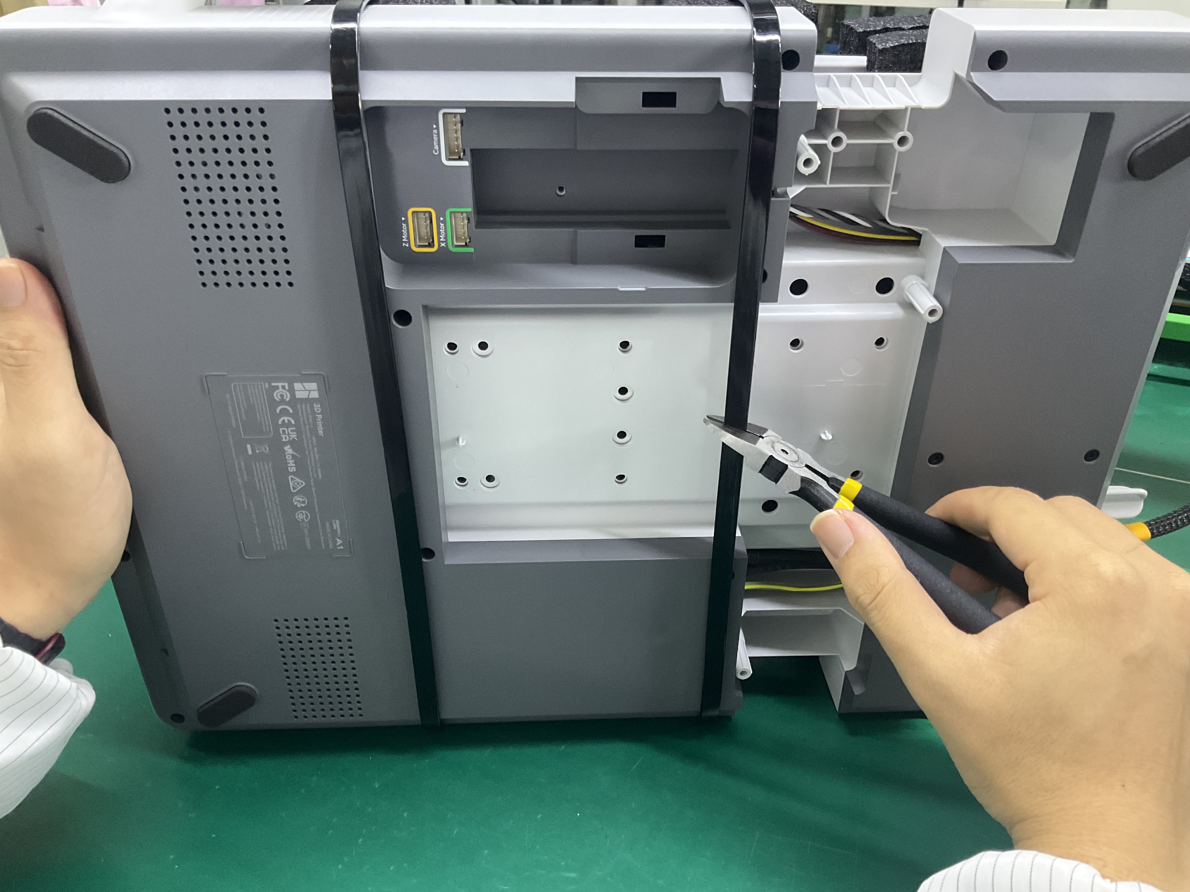
¶ 2. Unlock the heatbed by cutting the bottom zip tie.
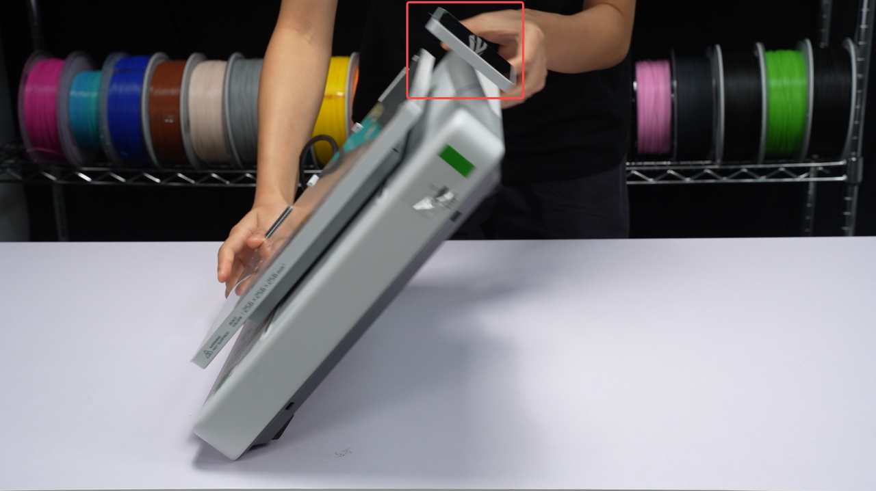
¶ Step 4: Assemble the printer base and printer frame.
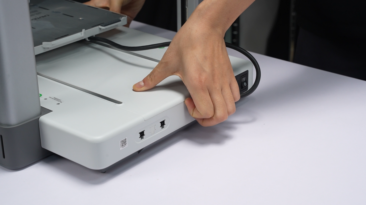
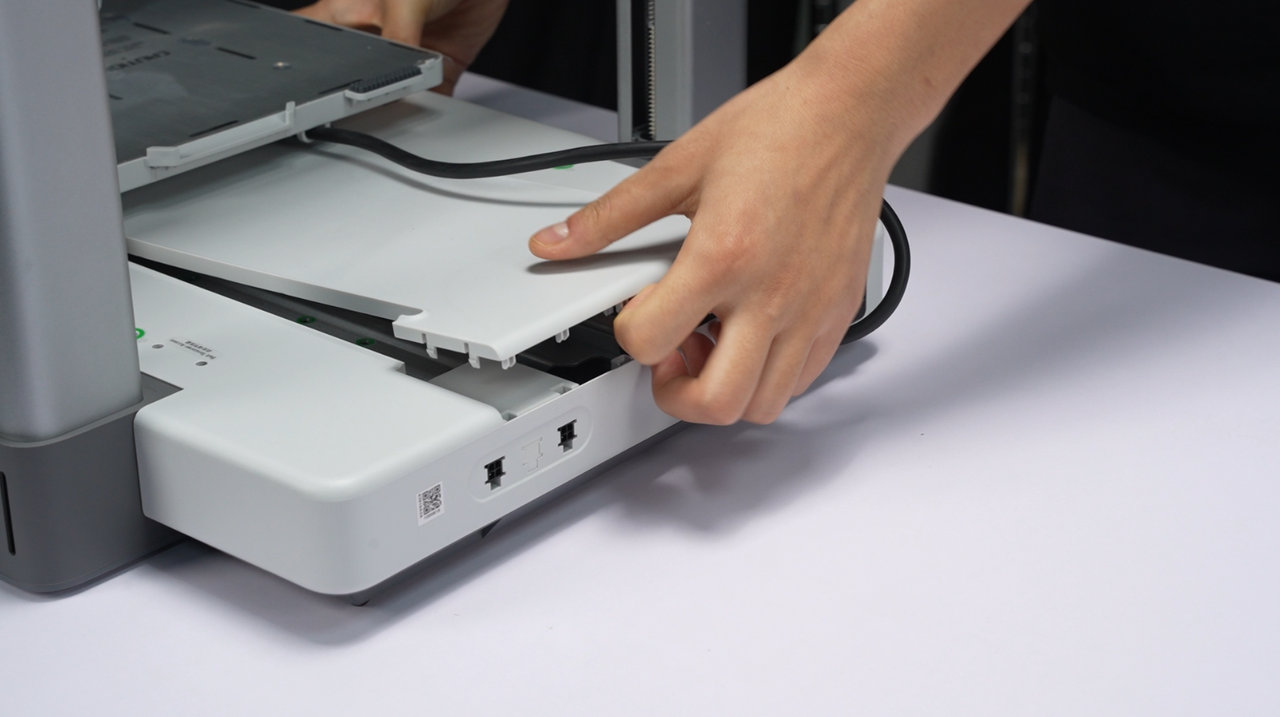
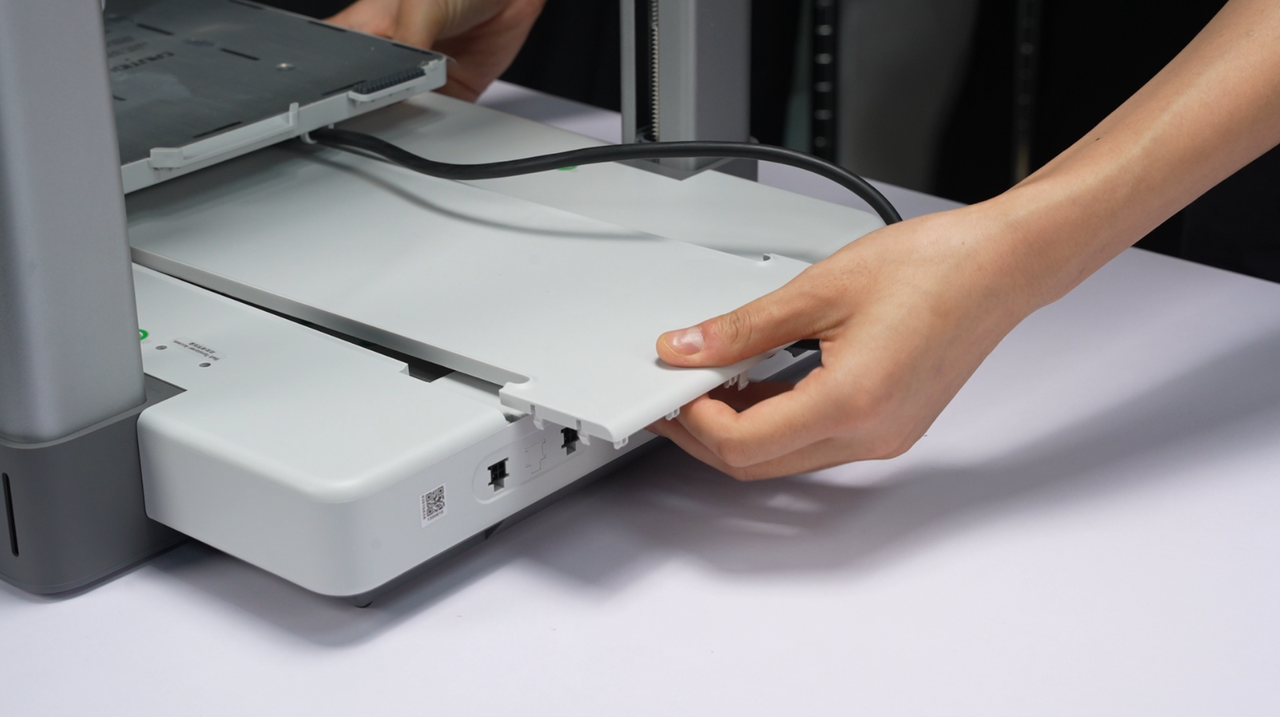
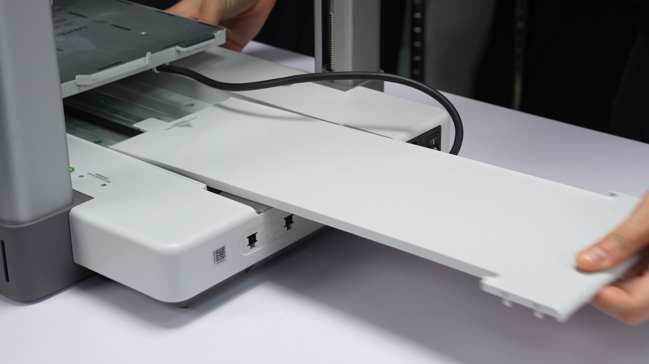
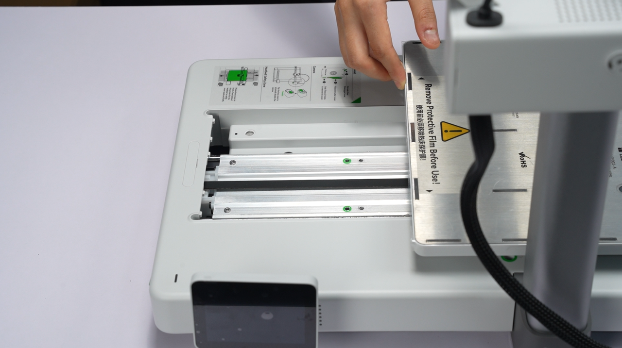
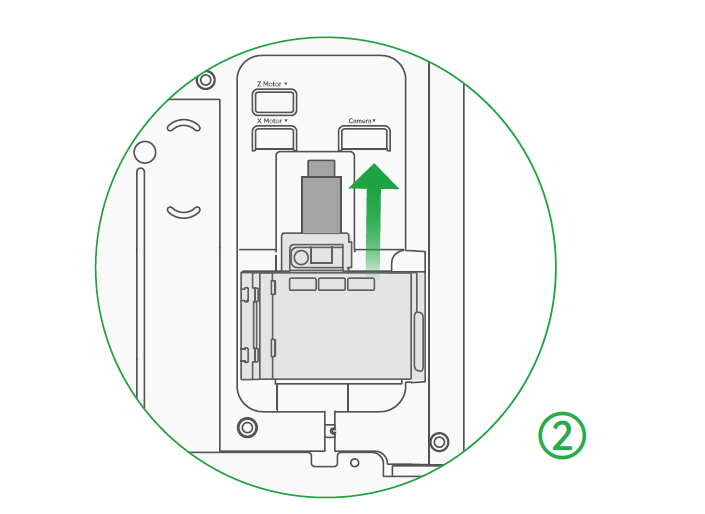
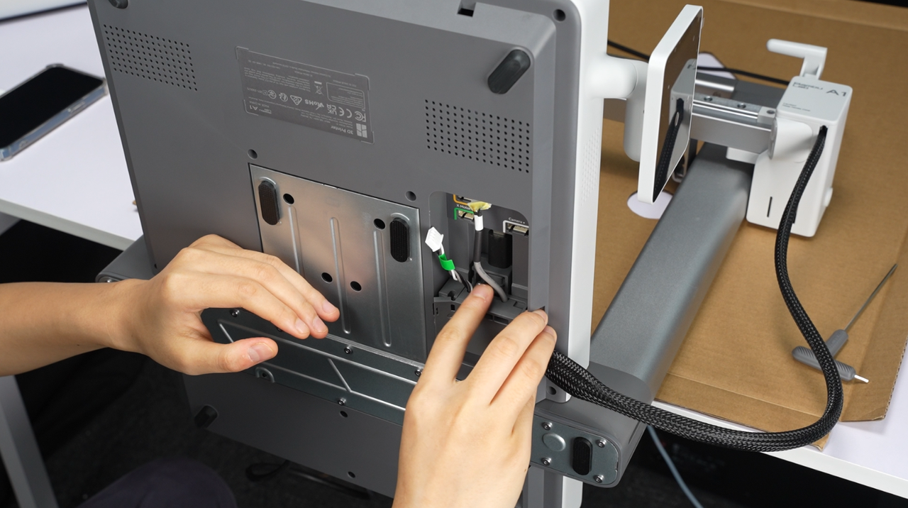
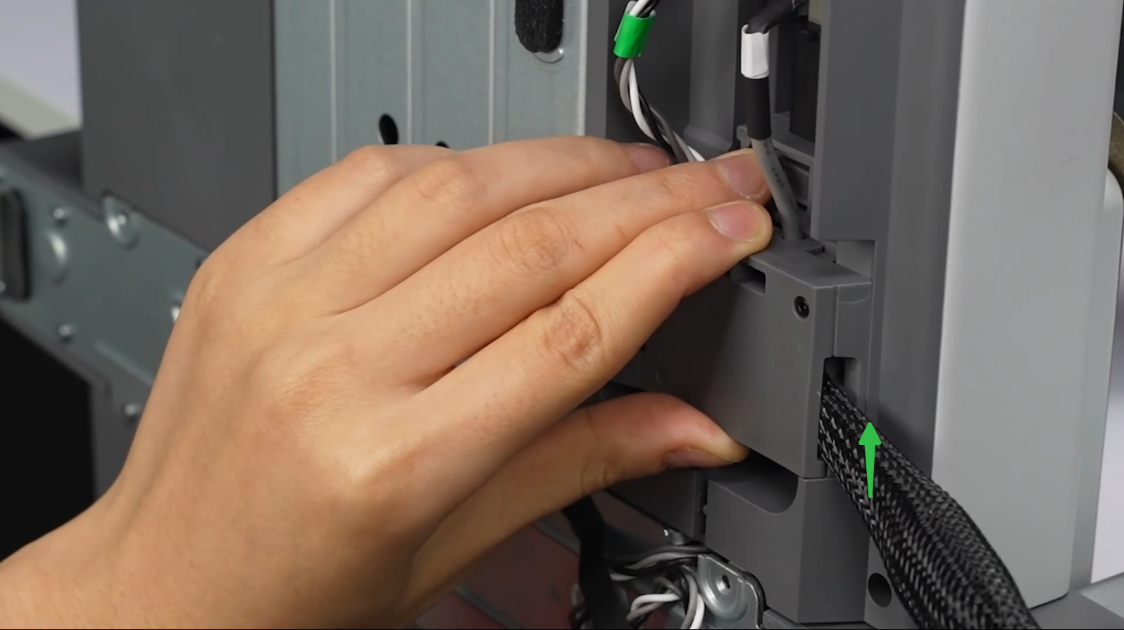
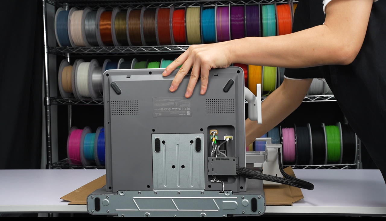
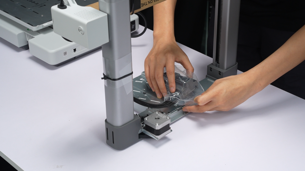
¶ 1. Place the printer frame as shown in the picture, removing the cable box on the base.
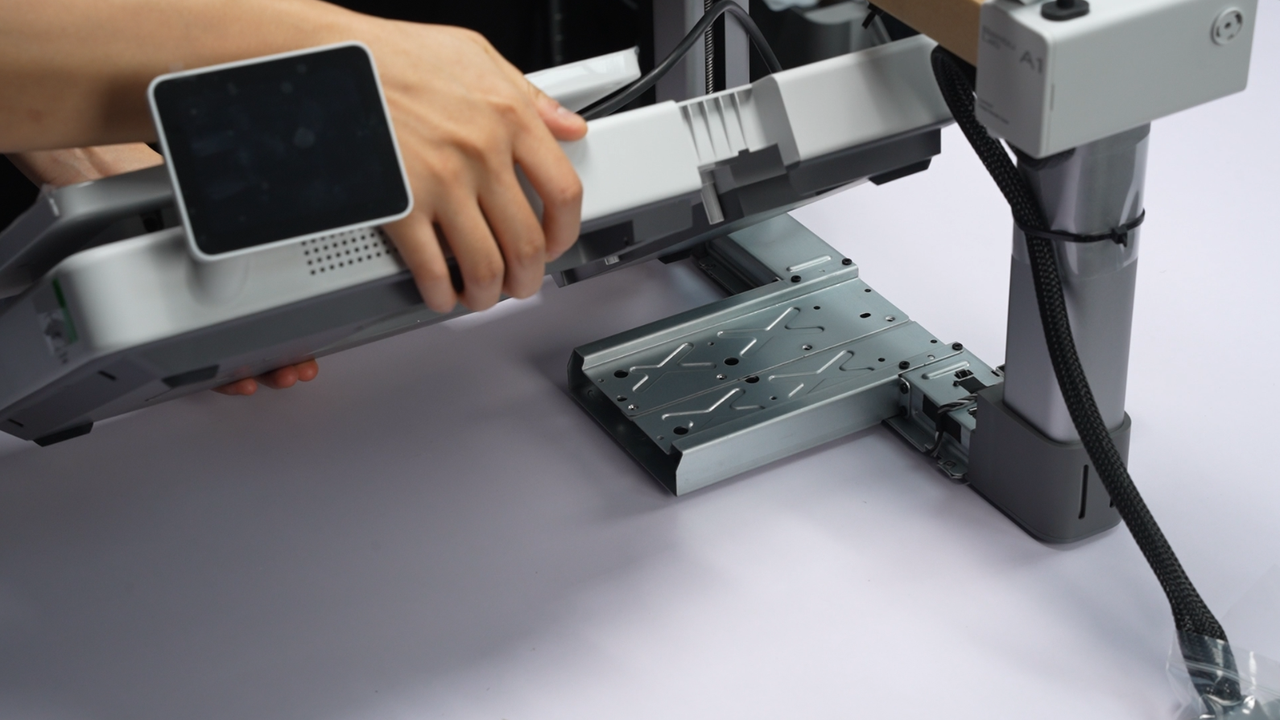
¶ 2. Tilt the Base Housing about 45 degrees to pass through the Printer Frame. (Use the screen as an indicator for orientation; it is recommended to lift the side with the screen higher for more effortless operation)
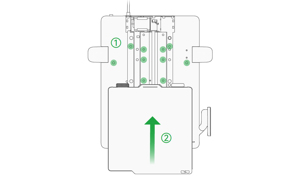
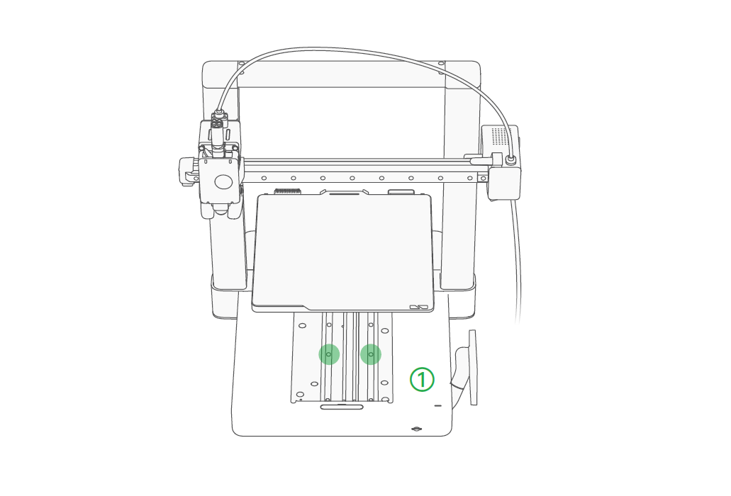
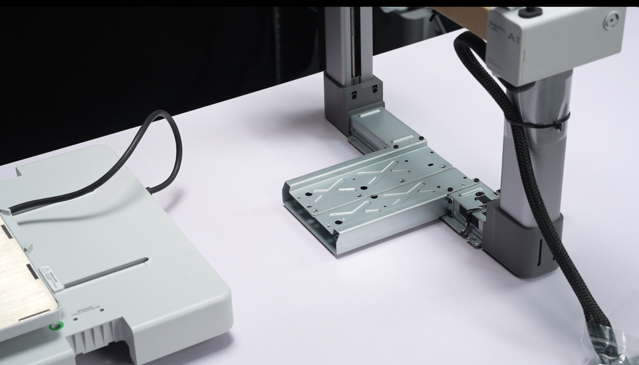
¶ 3. Align the slot with the Printer Frame as shown in the picture.
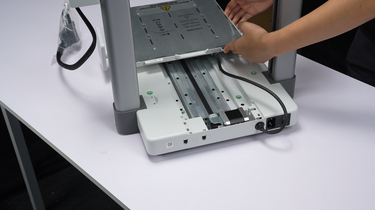
On the new A1 printers, there will be two versions of a stopper near the heatbed cable.
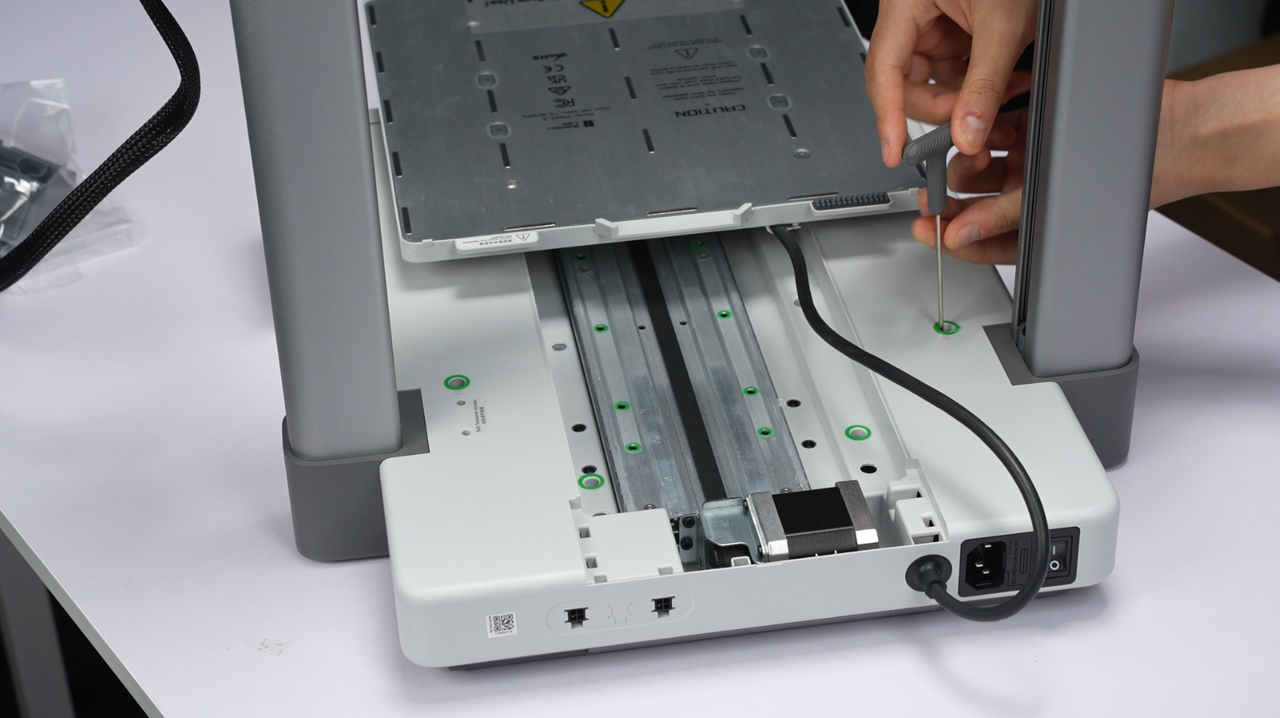
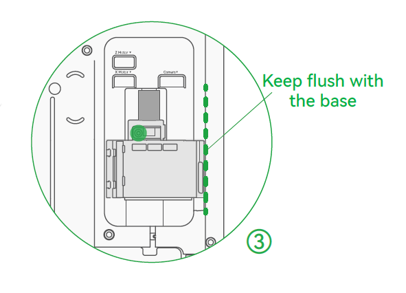
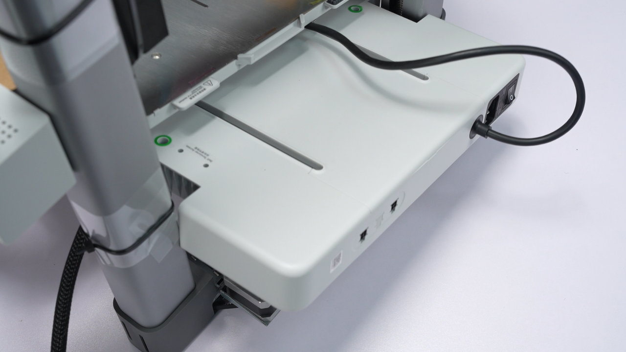
¶ 4. Slowly lower the Base Housing until fully flush with the Printer Frame on the table.
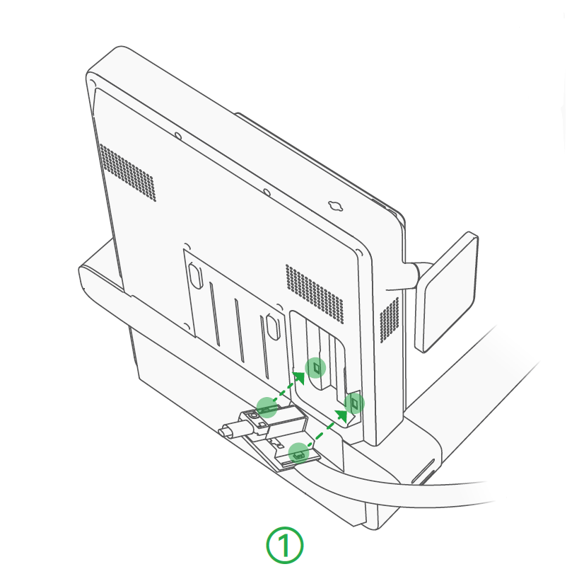
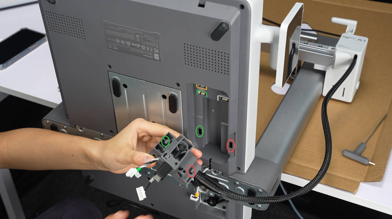
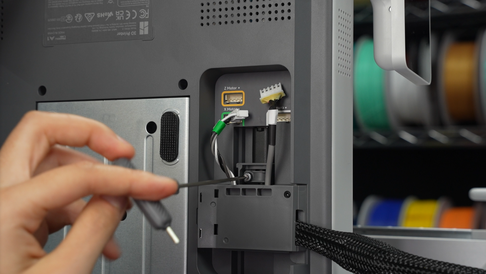
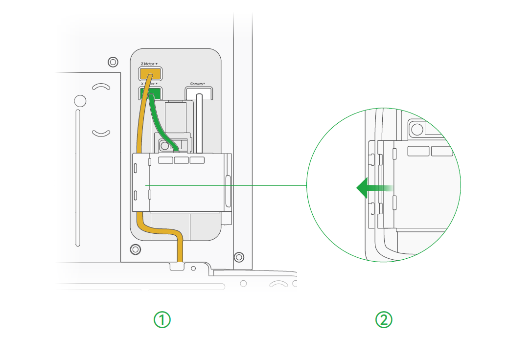
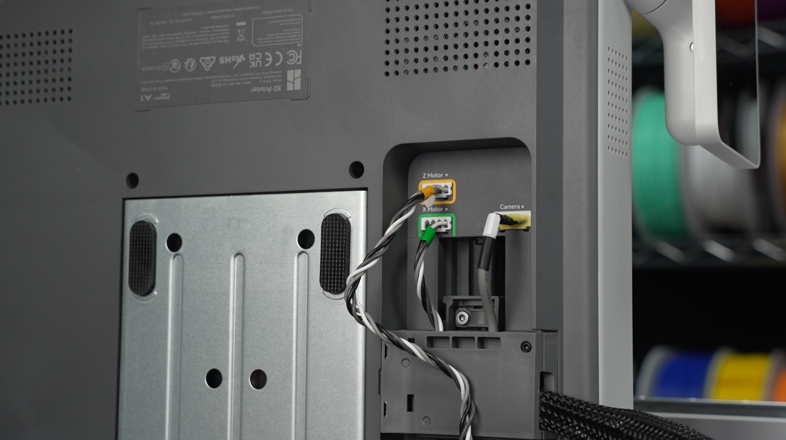
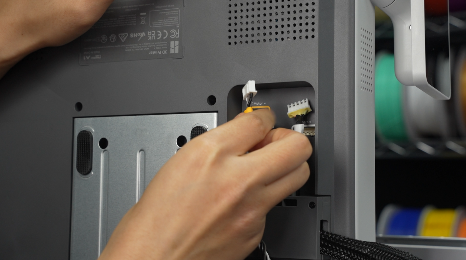
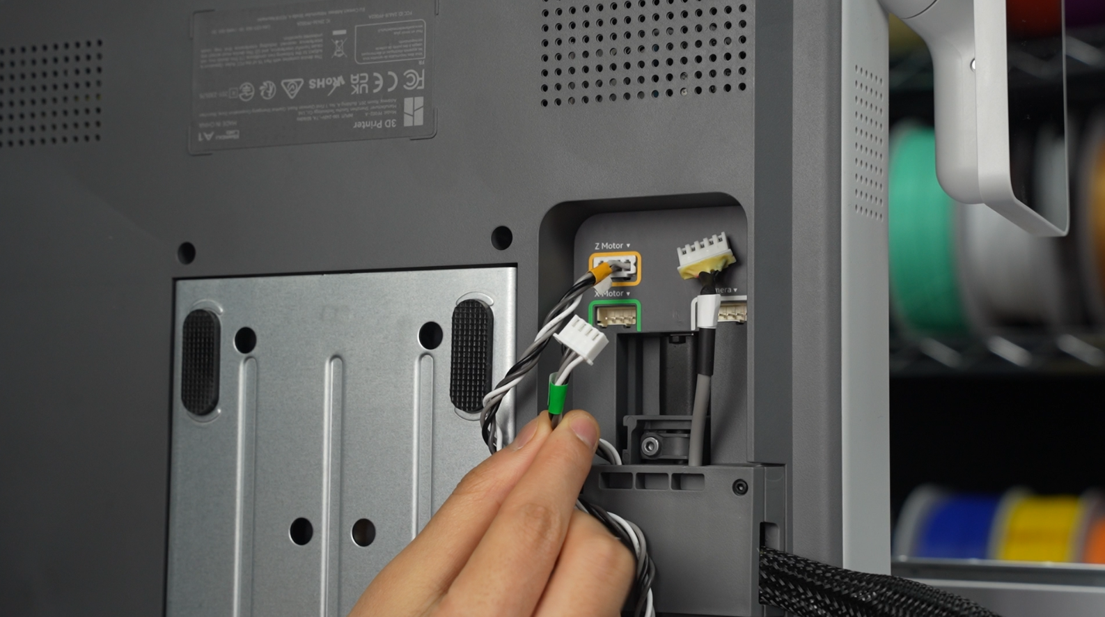
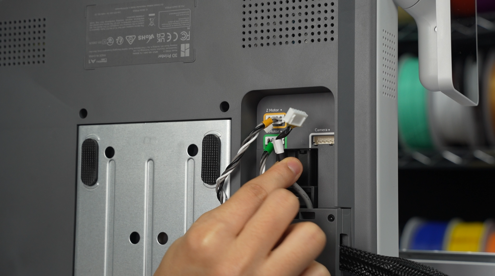
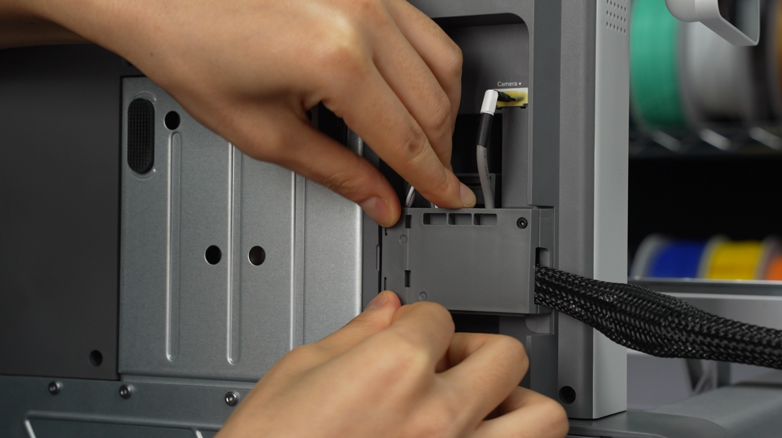
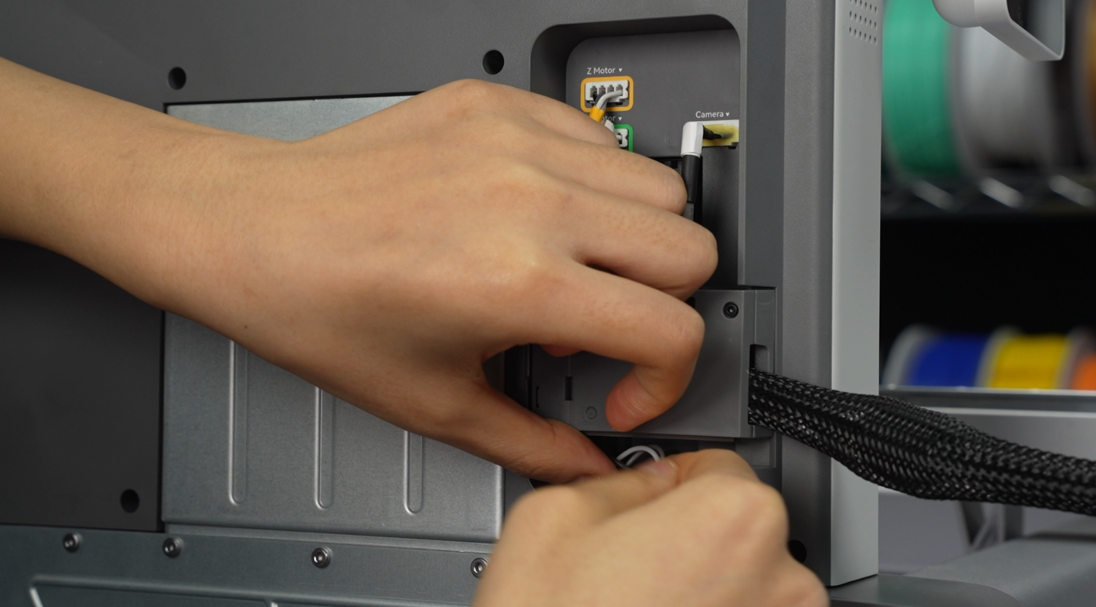
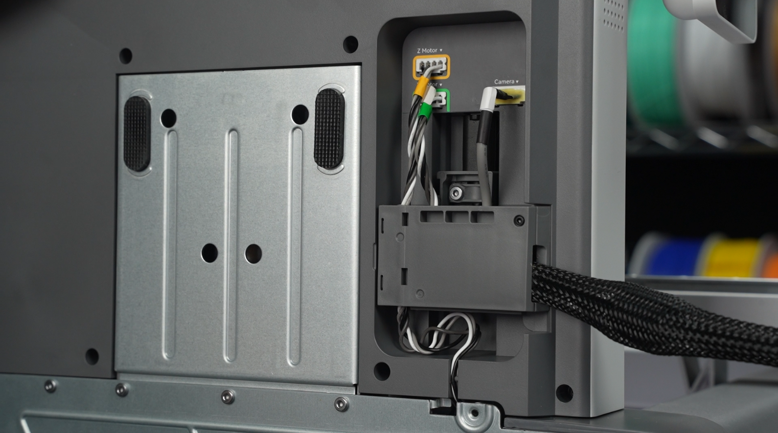
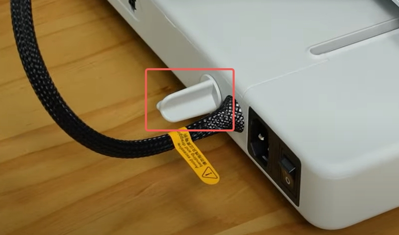
¶ 1. Plug in the three harnesses according to color.
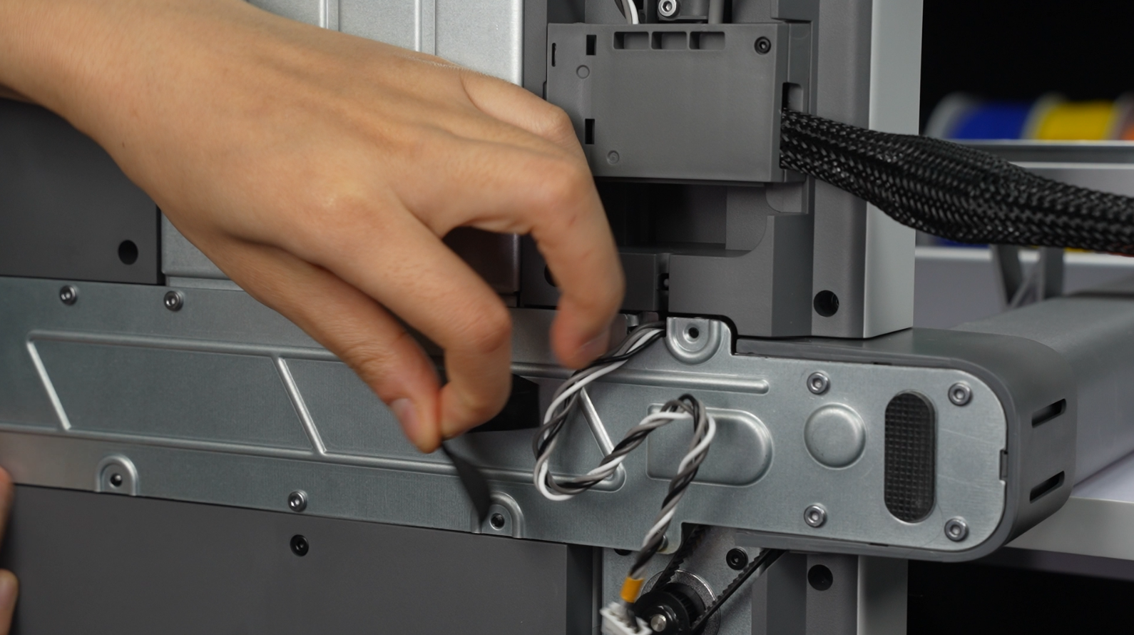
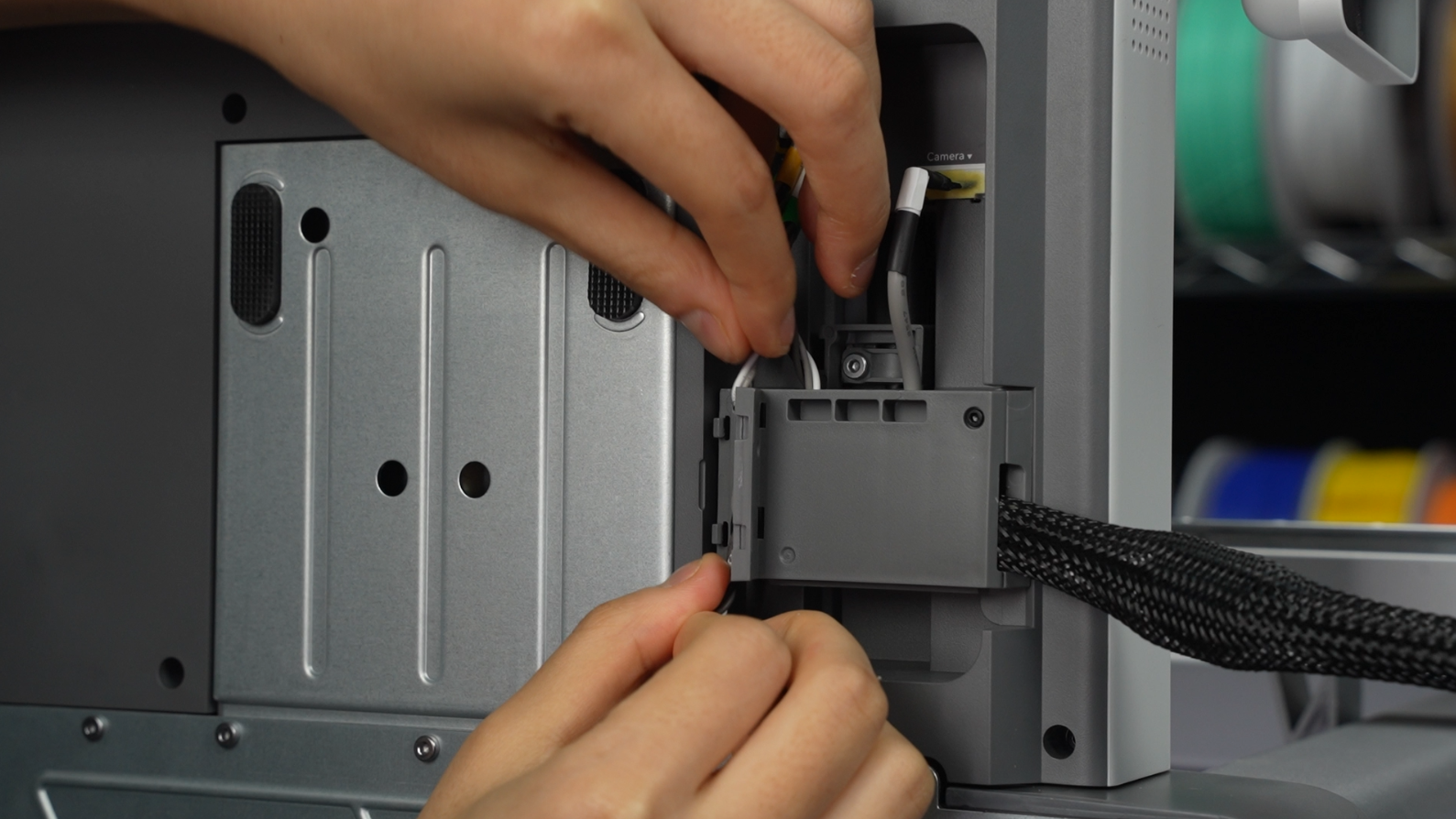
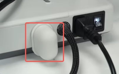
¶ 2. Insert the cable with the yellow label into the cable slot, then close the cable box cover.
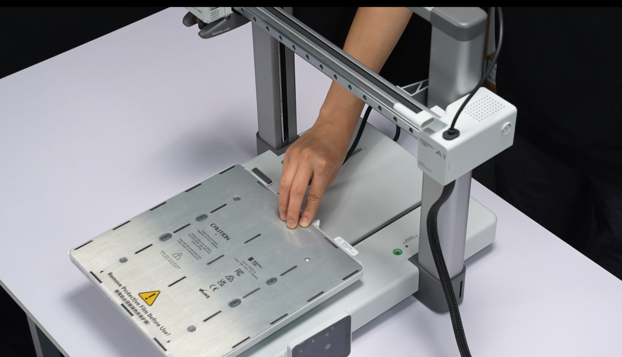
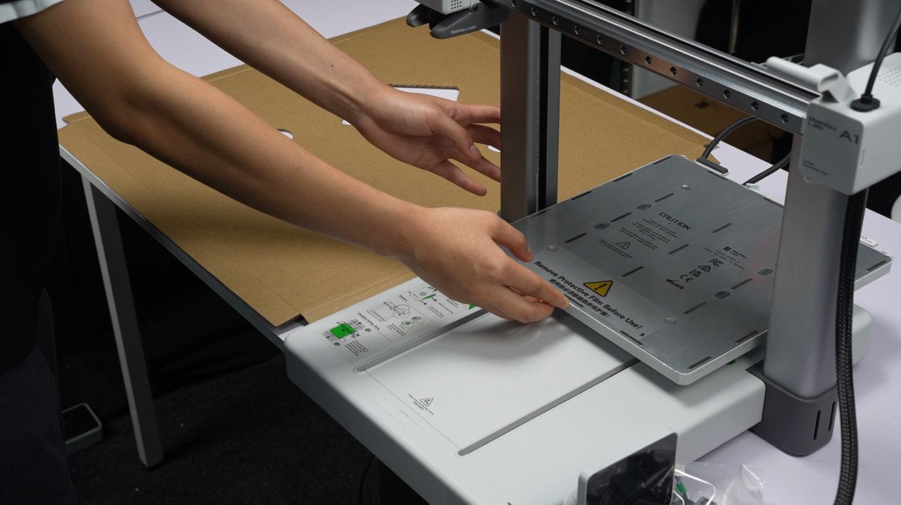
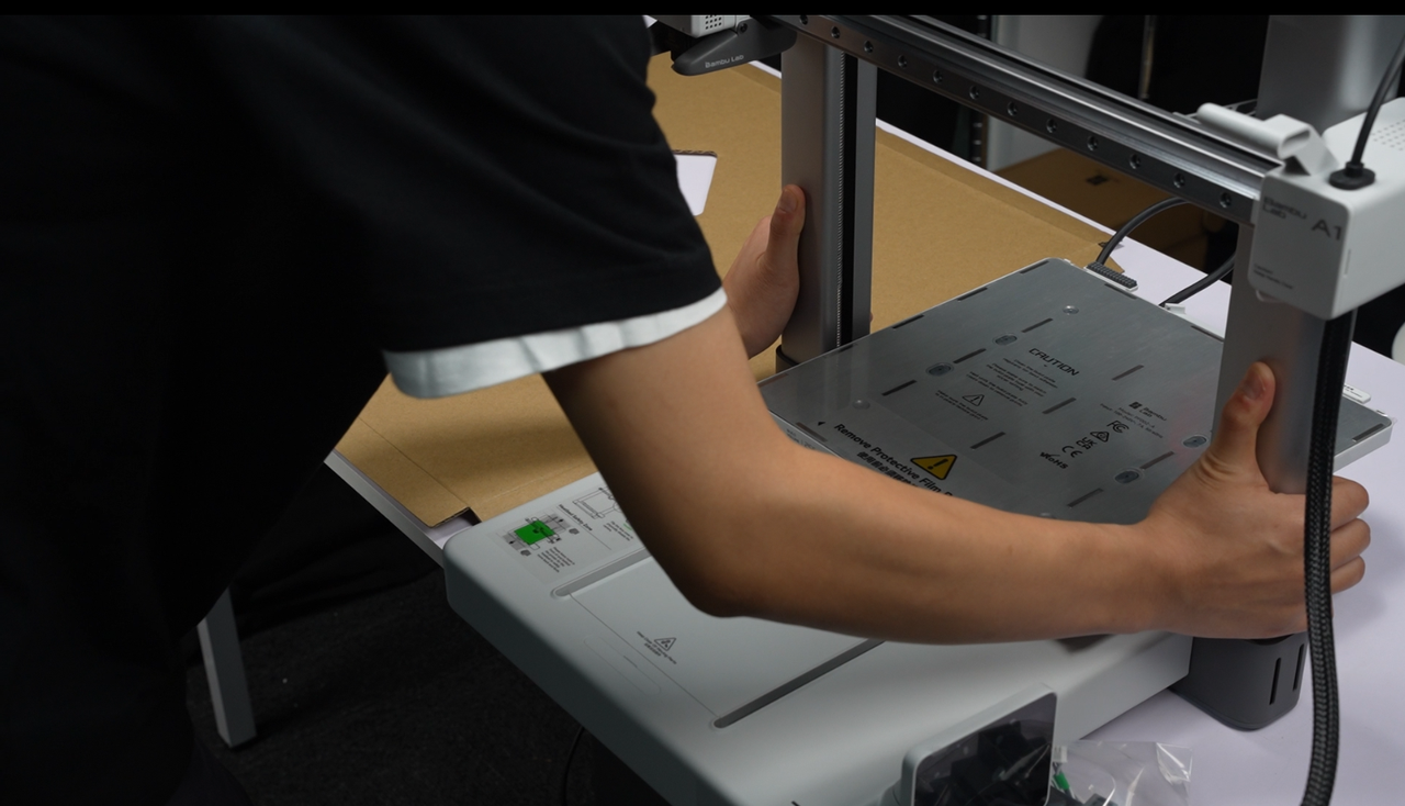
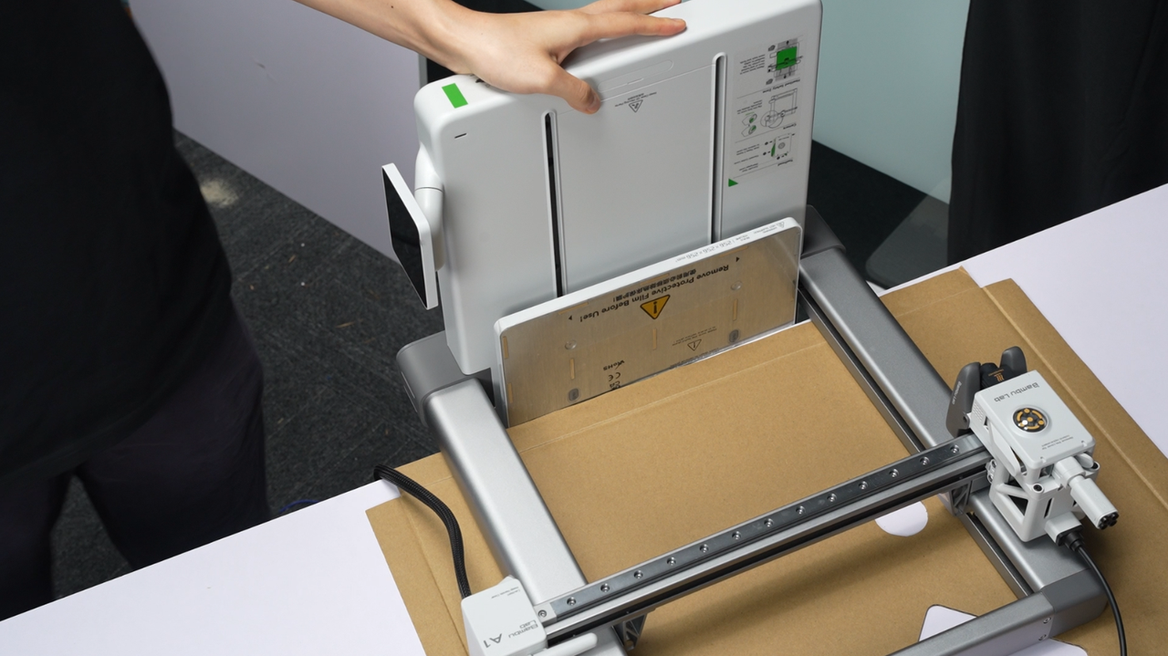
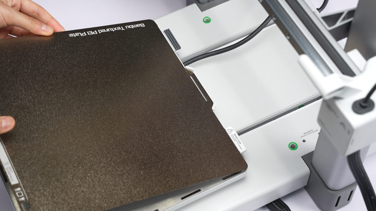
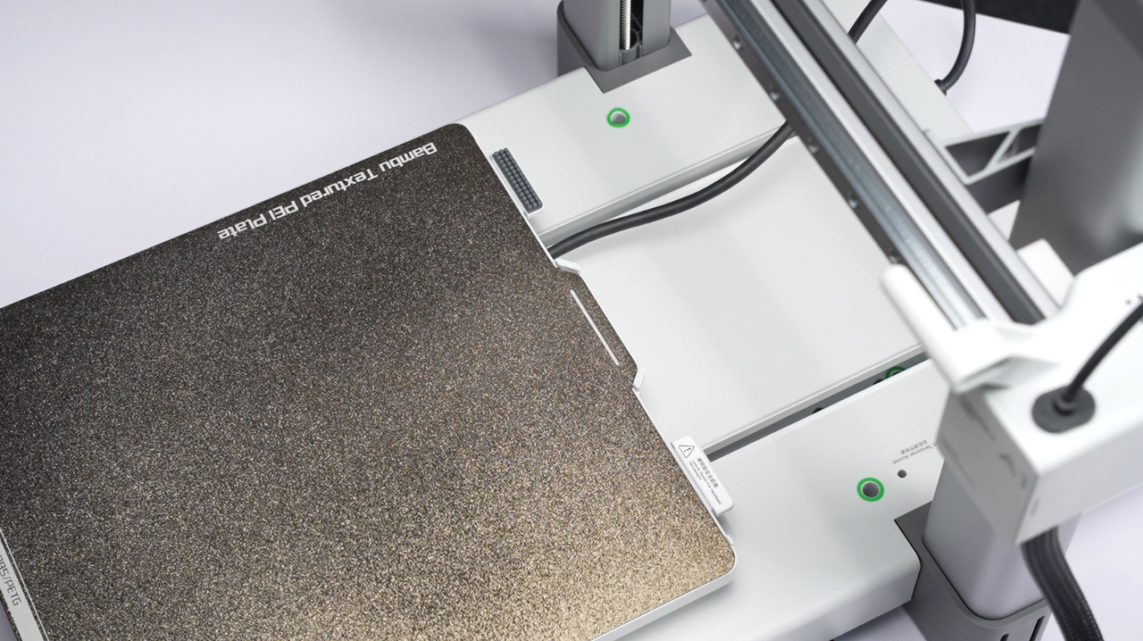
¶ Step 13: Place the printer upright, peel off the protective film on the surface of the heatbed, and place the build plate.
The packaging methods of machines shipped at different time periods may vary slightly, and some of the printers require removing the protective film on the heatbed surface. Please refer to the labeling on the bed surface to determine whether the film should be removed.
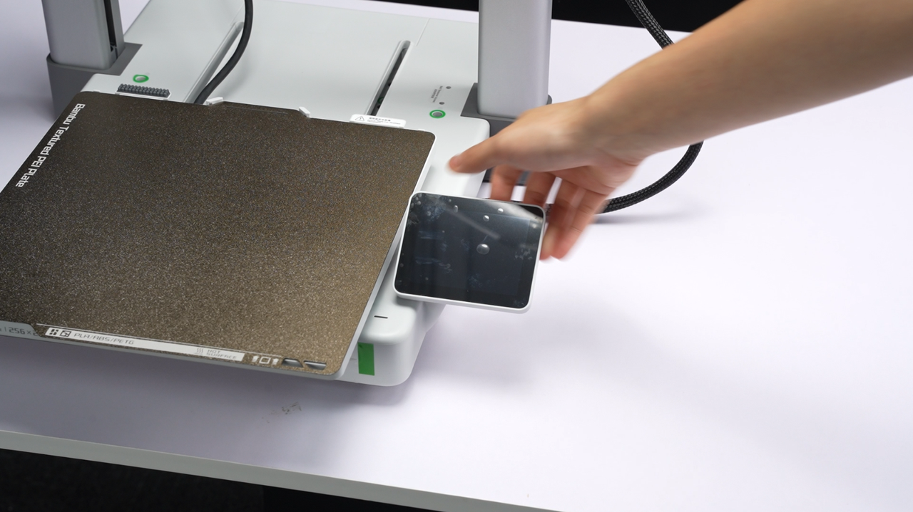
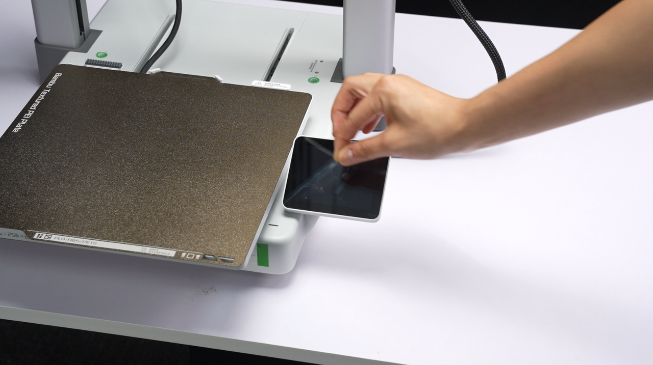
¶ Step 14: Fold out the touchscreen and peel off the screen protective film.
¶ Fold out the touch screen, and make sure the touch screen is in place, as shown in the picture.
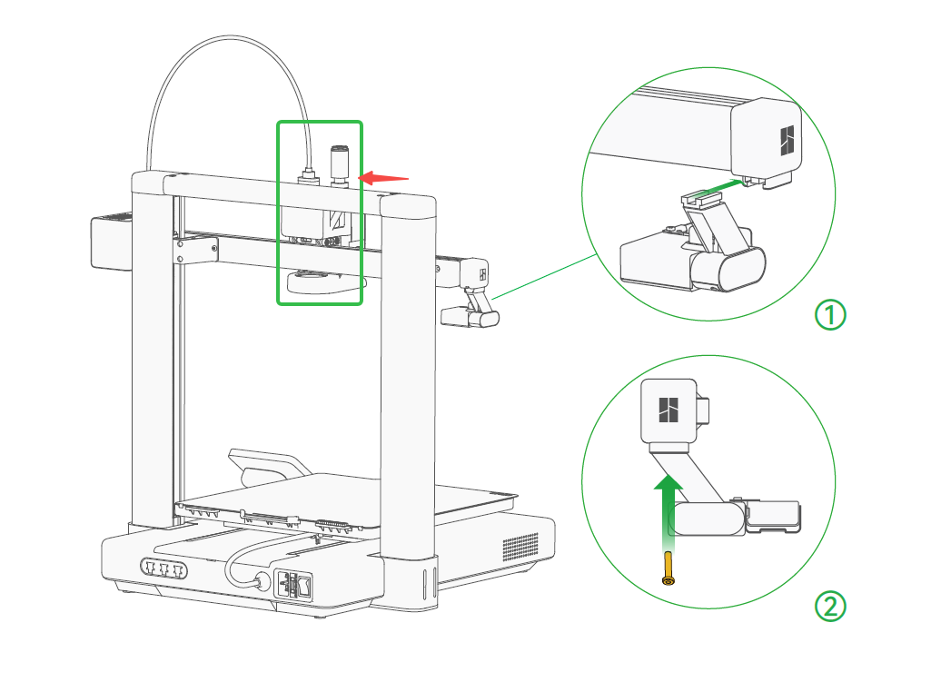
¶ If the tool head is moved to the far left during operation, please gently push the tool head towards the motor cover before installing the purge wiper, allowing space for installation.
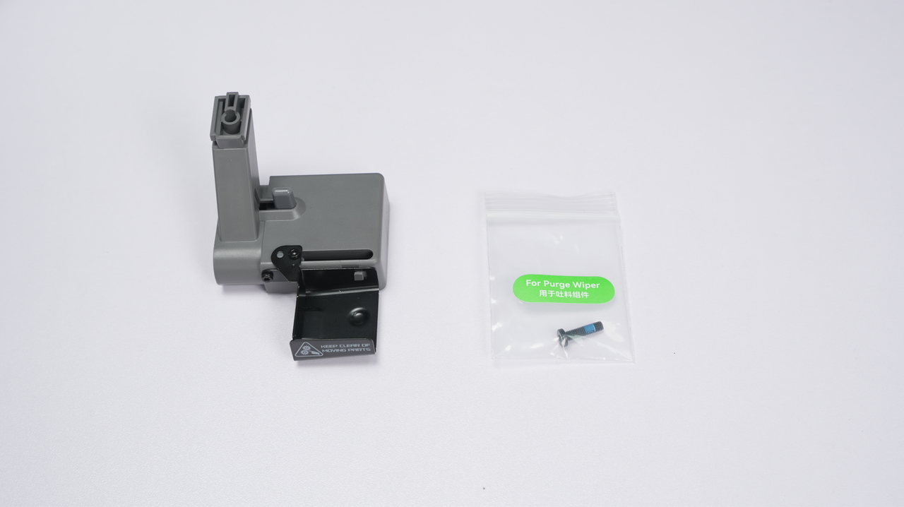
¶ Slide the Purge Wiper unit into the slot at the end of the X-Axis from the back to the front. Install the 1*M3-12 screw (For Purge Wiper) from the accessory box to fix the Purge Wiper in place.
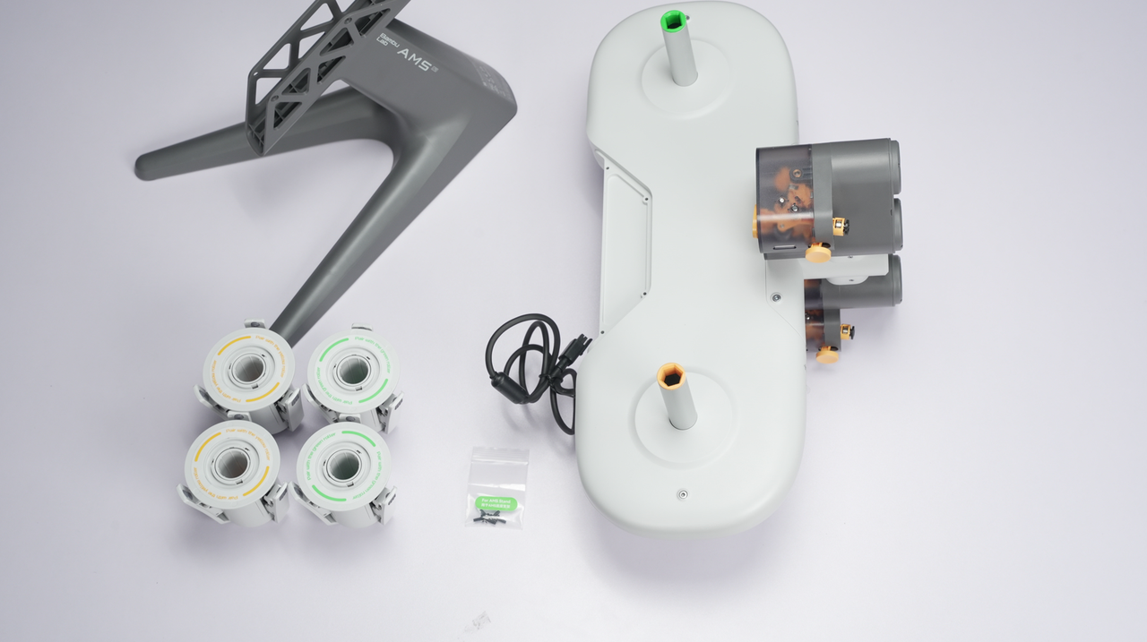
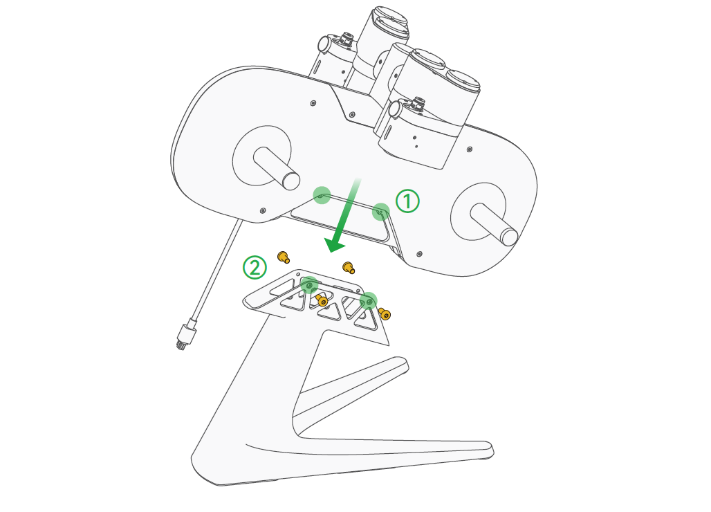
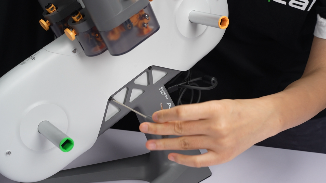
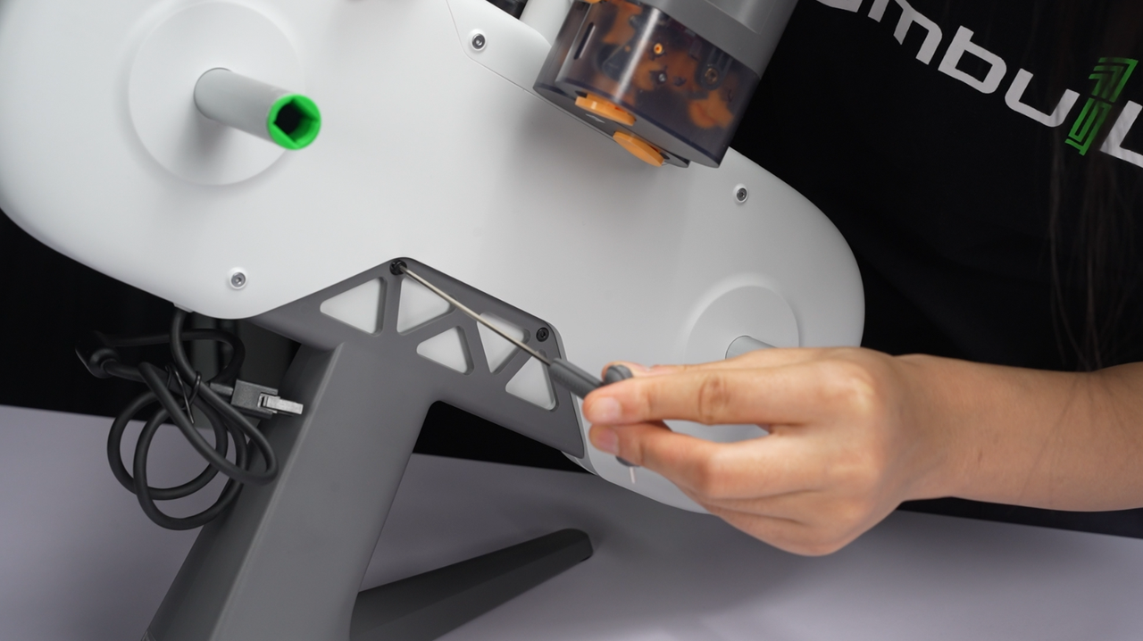
¶ 1. Put the AMS lite body on the stand. (cable on the upward end)
¶ 2. Secure the AMS lite with the 4*BT3-8 screws (For AMS Stand) from the accessory box
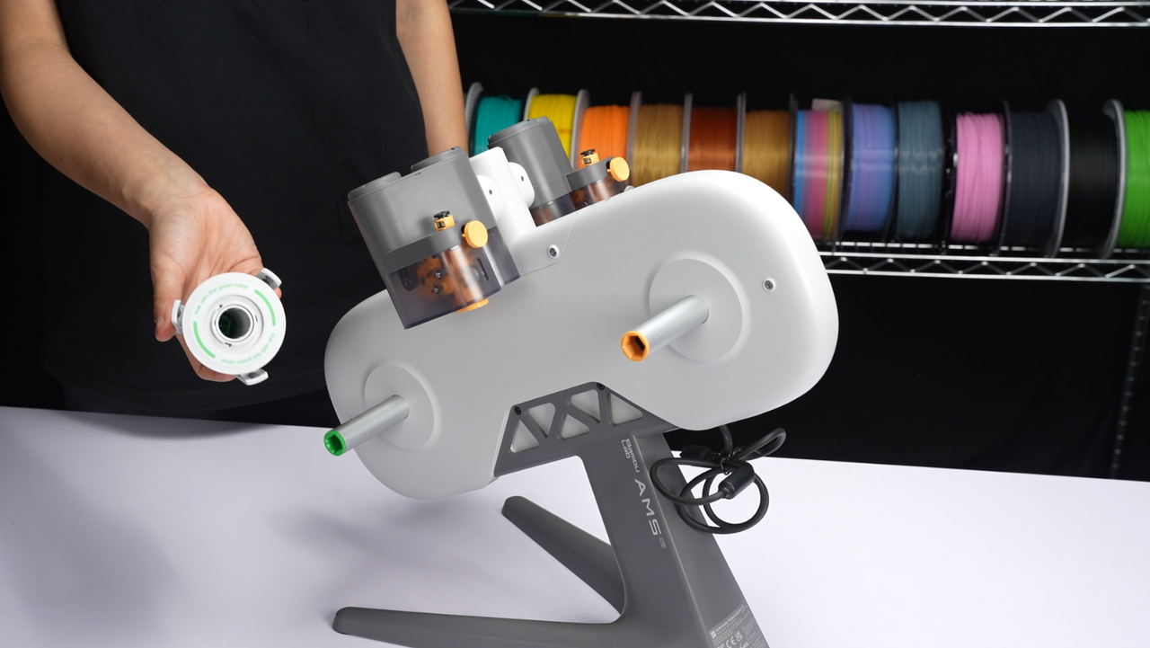
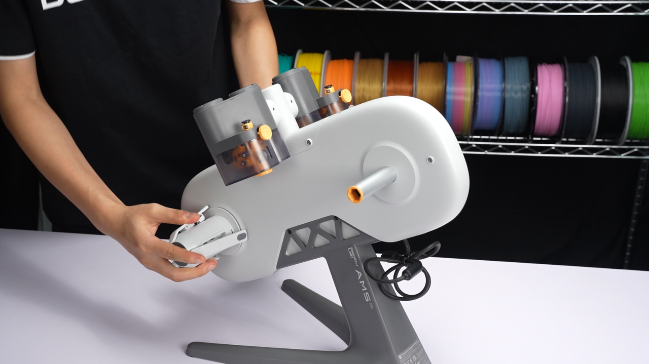
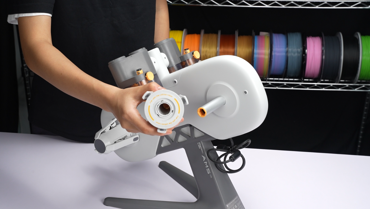
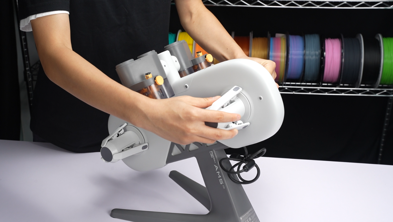
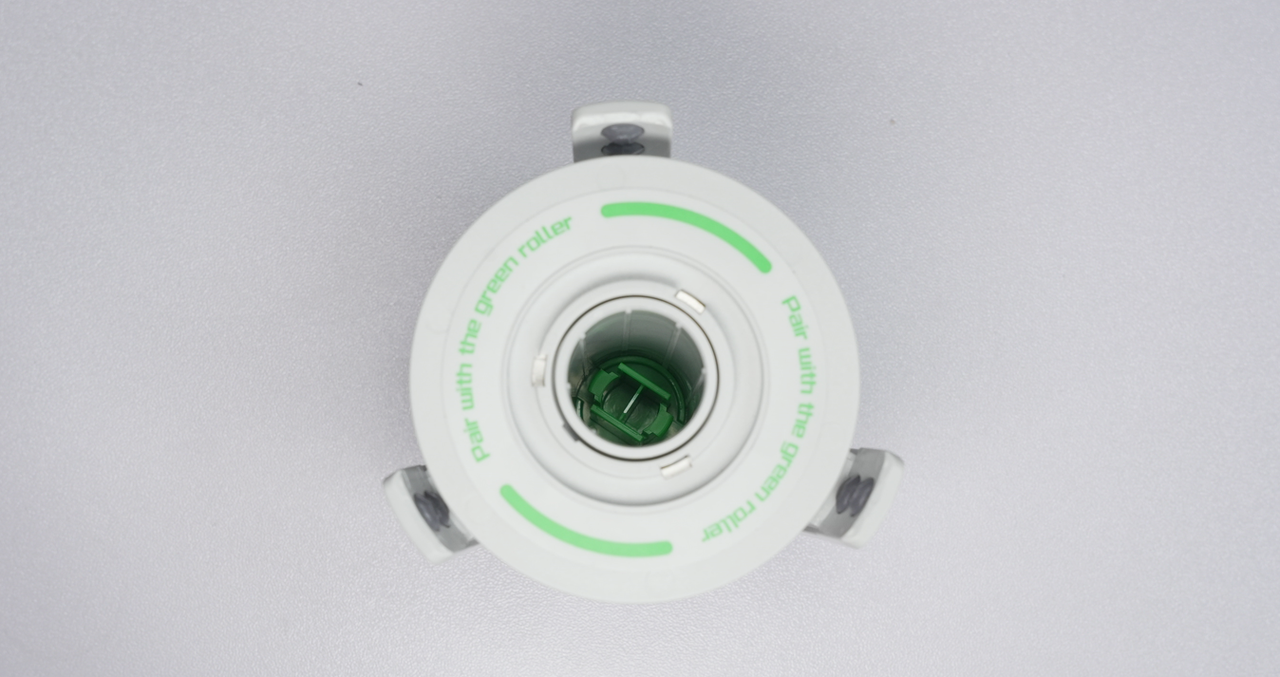
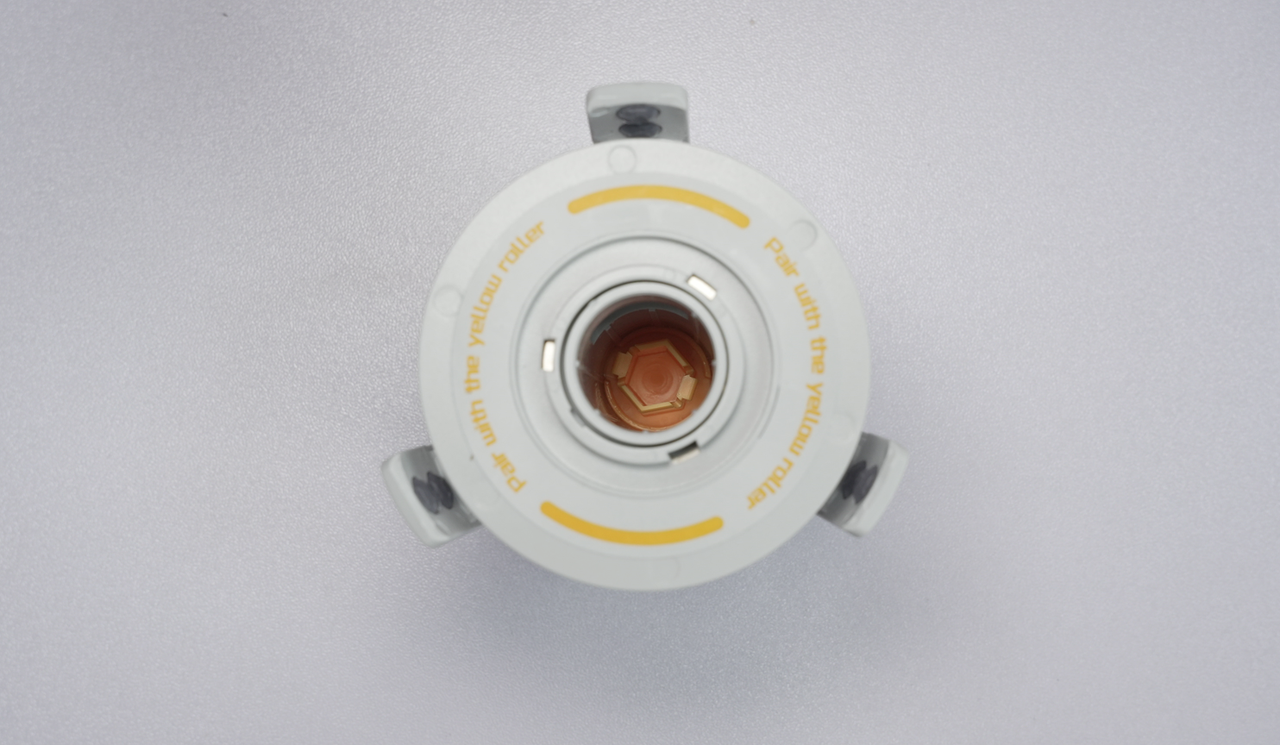
¶ 3. Slide the rotary spool holders on (in), being careful to match colors to avoid damaging any parts. (as shown in the diagram, yellow matches with yellow, green matches with green)
The yellow rotary spool holders have a hexagonal clip inside, making aligning with the locking position relatively easier. The green rotary spool holders are rectangular, so it is recommended to align them roughly with the hole before insertion, then move them parallelly with slight adjustments to ensure alignment with the locking position.
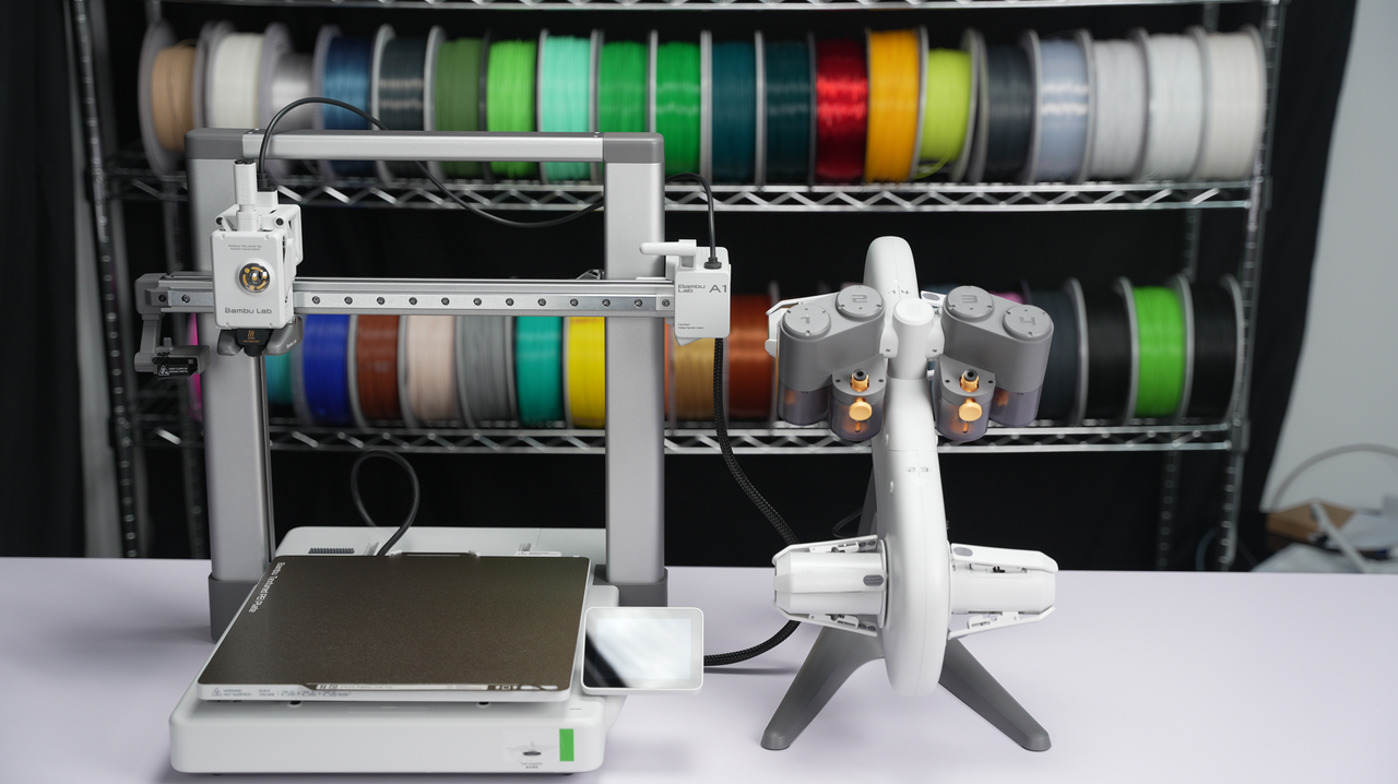
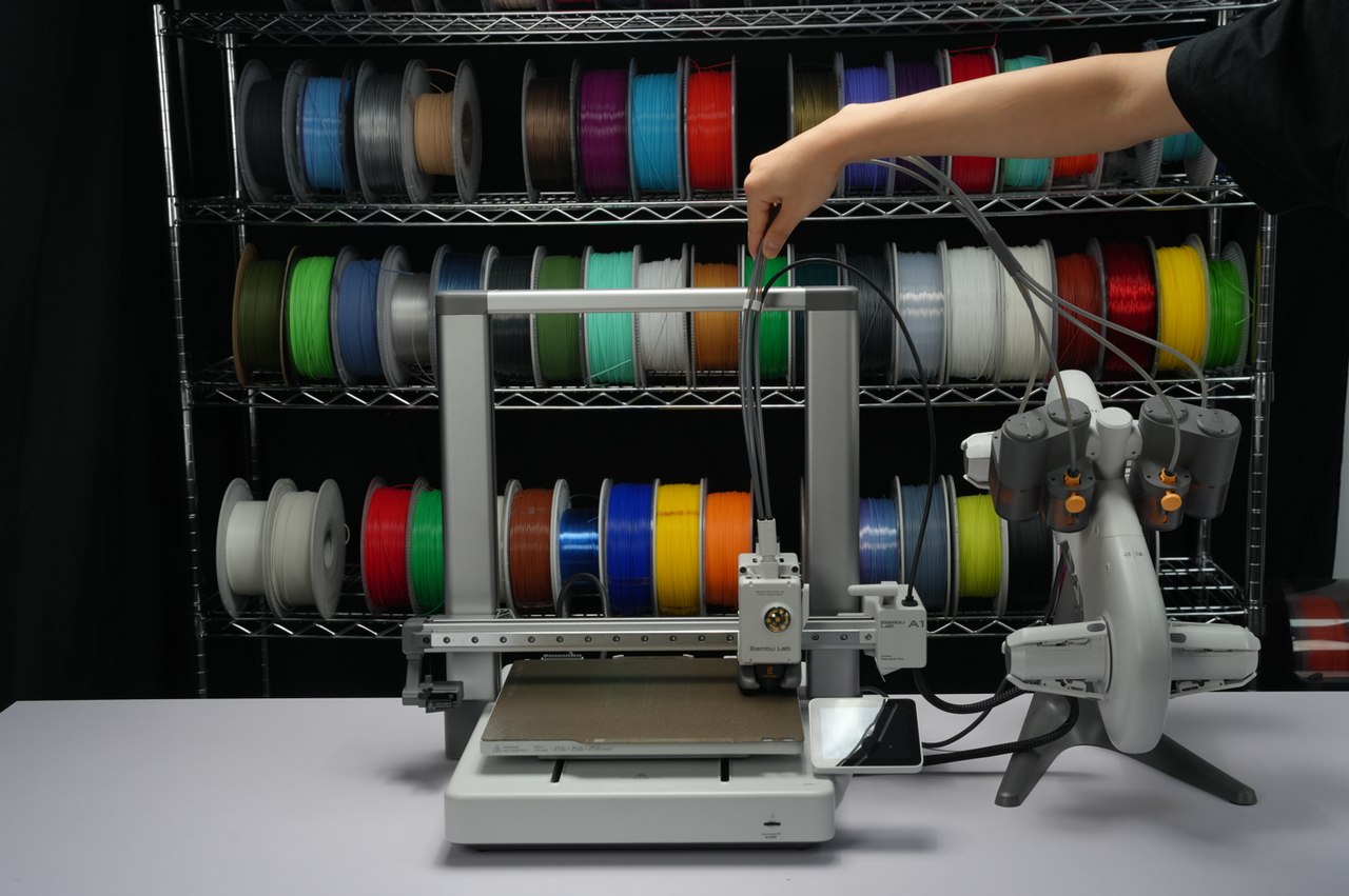
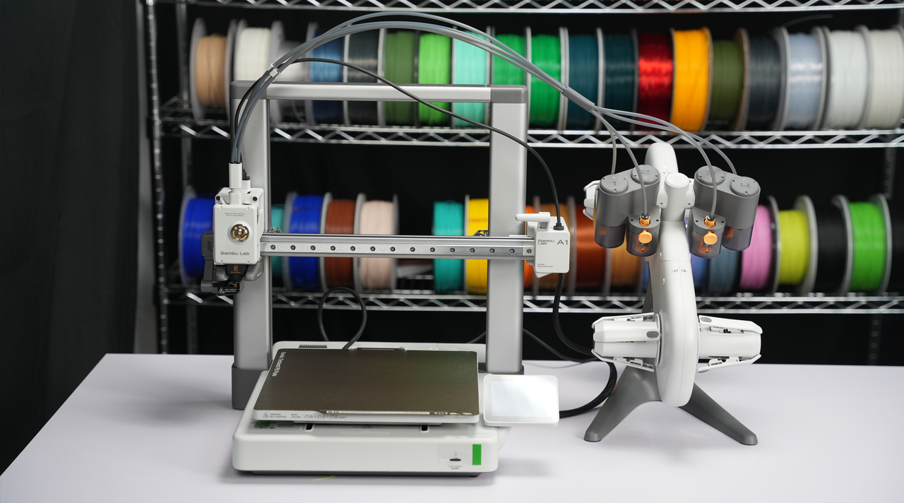
¶ 4. Place the AMS lite on the right side of the A1 printer after successfully installing the rotary spool holders.
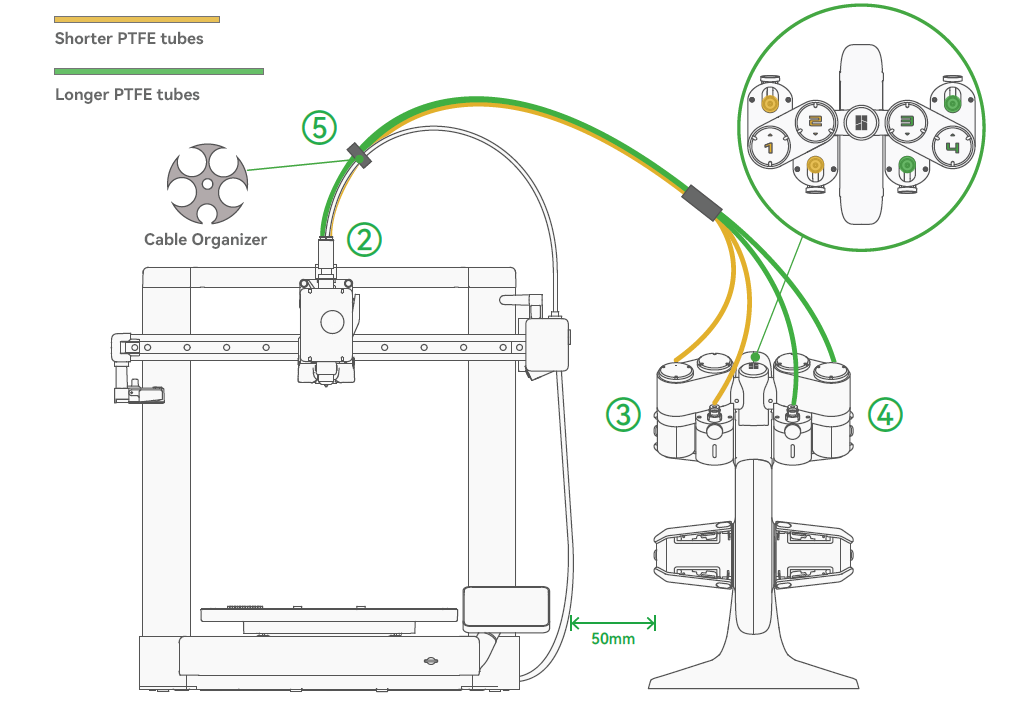
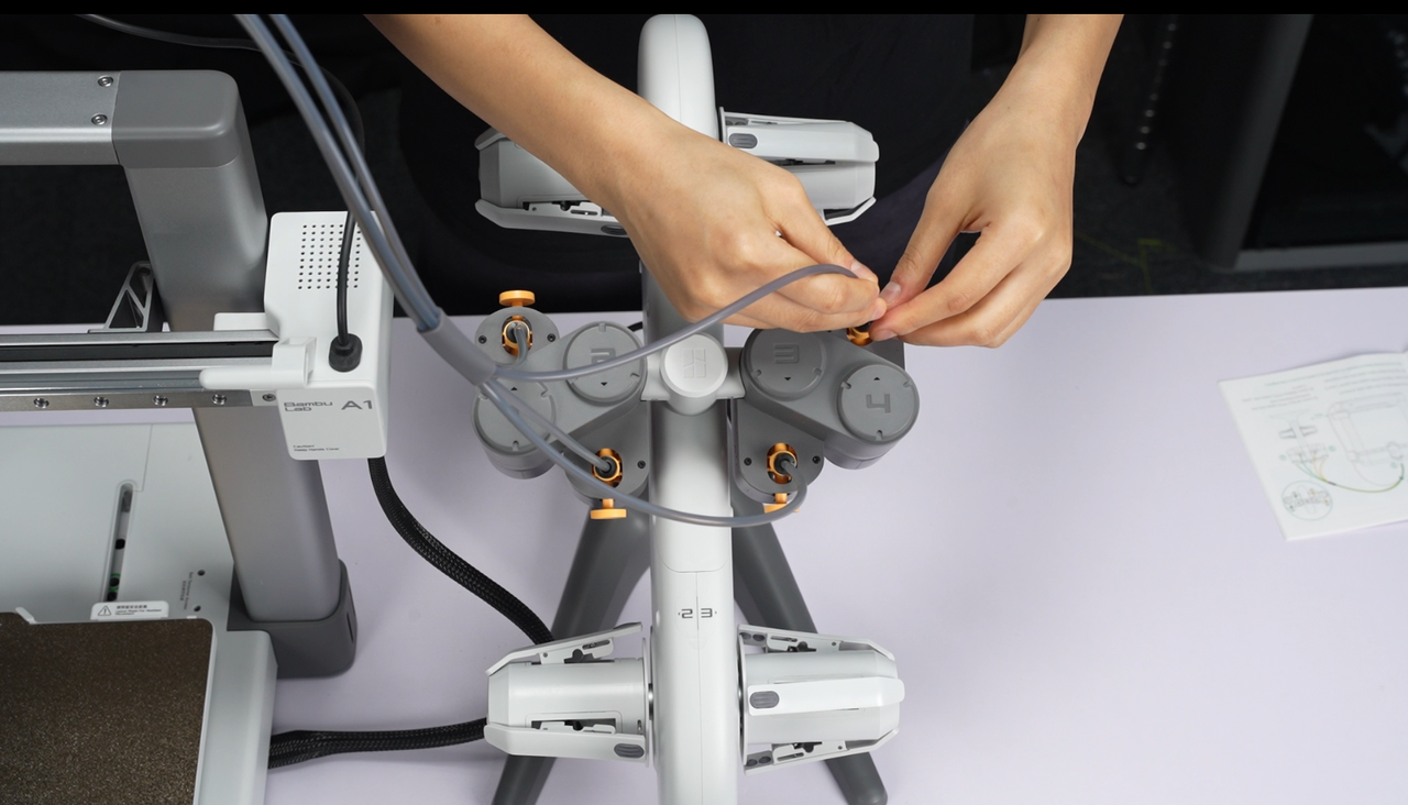
¶ 5. Insert all four PTFE tubes into the toolhead filament hub.
Insert two shorter PTFE tubes into ports 1 and 2. Insert two longer PTFE tubes into ports 3 and 4.
Friendly reminder: Ensure proper placement of the silicone organizer on the PTFE tubes of the AMS lite to avoid excessive feeding resistance and potential error.
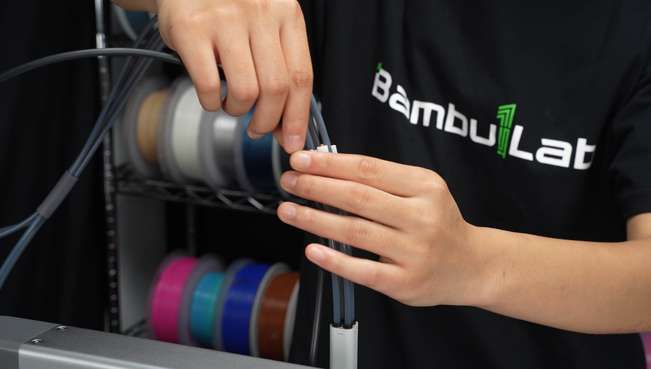
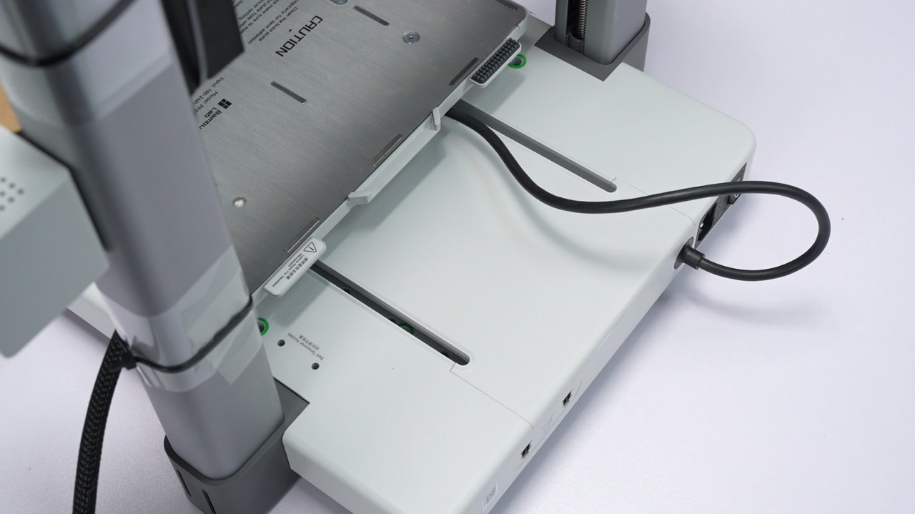
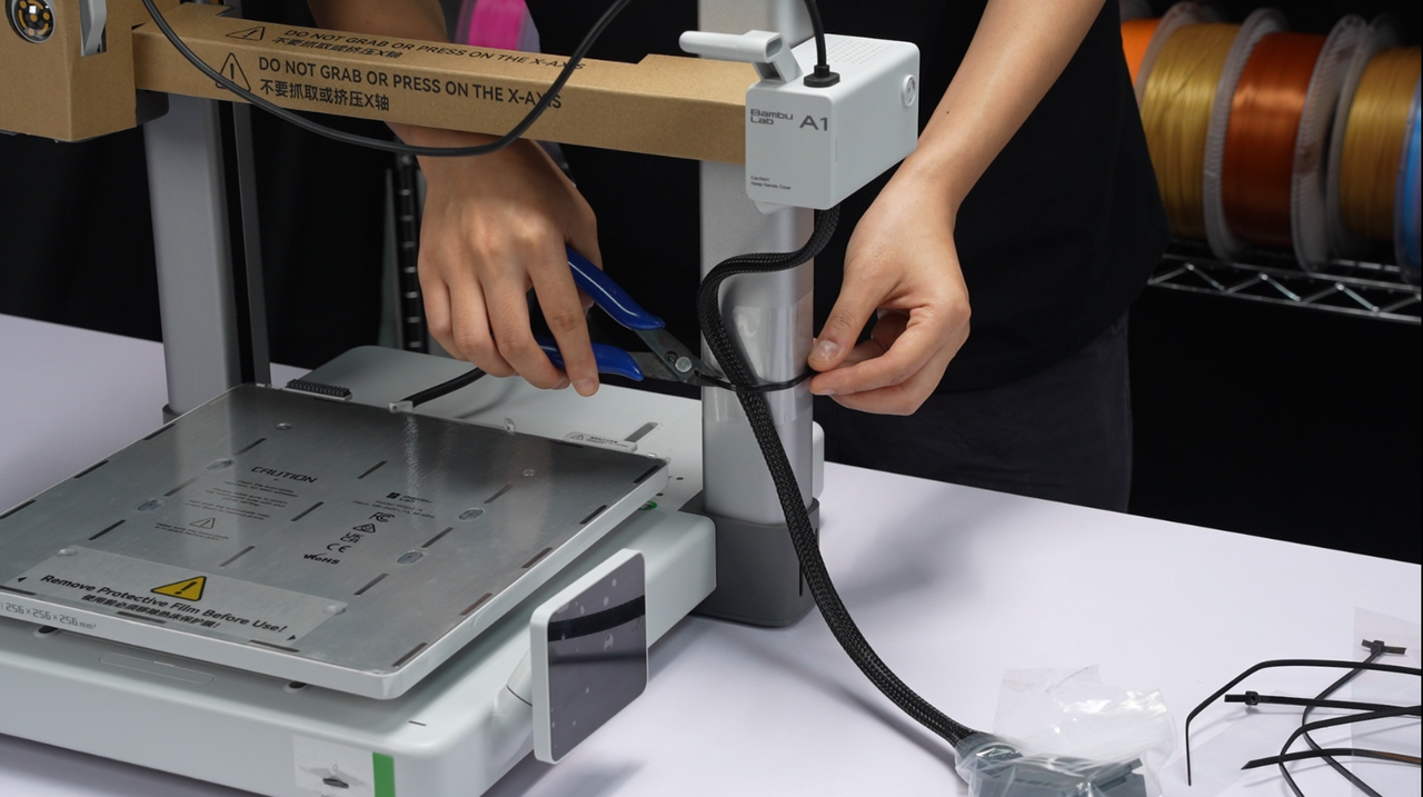
¶ 6. Insert the tool head cable into the organizer.
The optimal position for the organizer is to align the edge of the hub with the lower edge of the beam once it comes into contact with the hot end and heatbed. This is because, at this position, the likelihood of the Type-C interfering with the Z-axis column is minimized, thus avoiding any disruption to the Type-C connection.
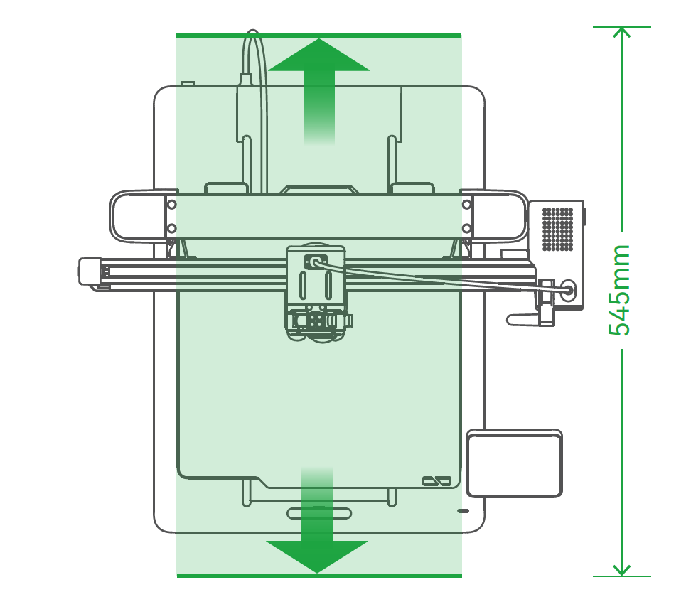
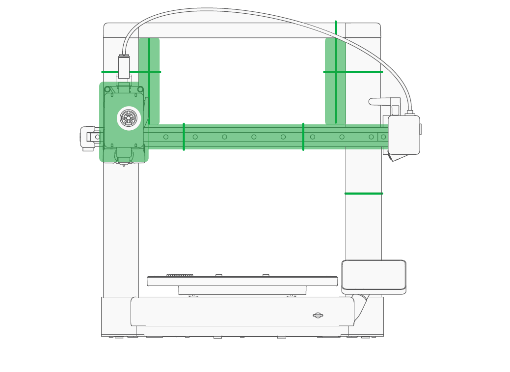
Please leave a safe amount of space for heatbed movement. (as shown in the diagram)
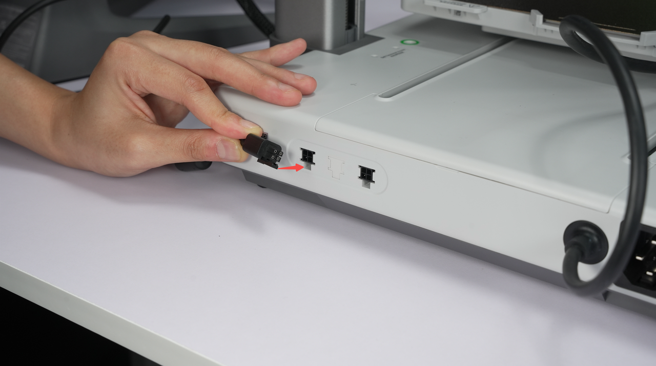
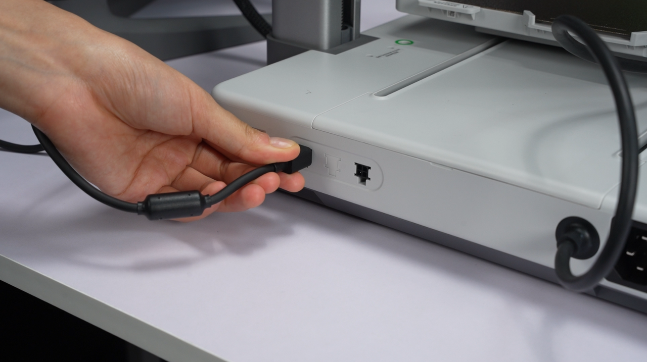
Plug the AMS lite 4-pin connector into the port on the A1 mini. (either one); Ensure that the 4-pin cable is inserted correctly and aligned with the direction of the protection clip.
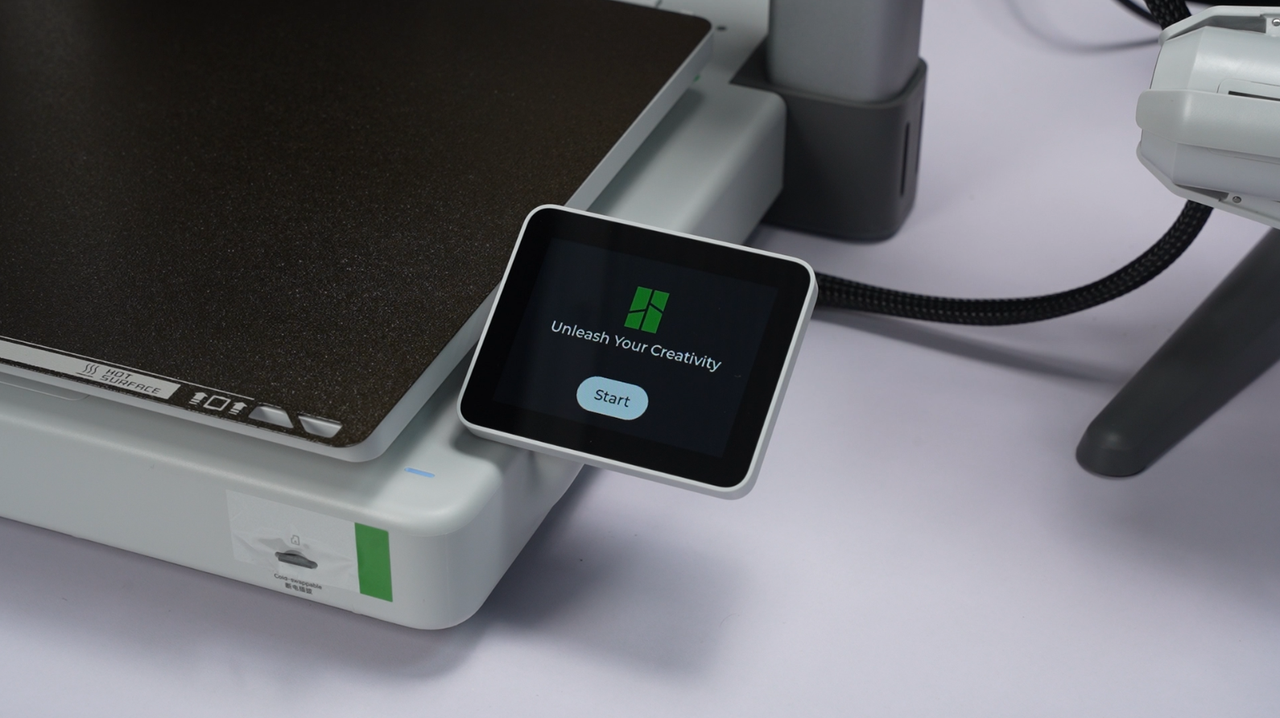
¶ Step 18: Follow the on-screen prompts to complete the initialization and calibration process.
Make sure the build plate is installed and cleaned. After powering on the printer, follow the prompts on the screen to complete the initialization and calibration of the printer.
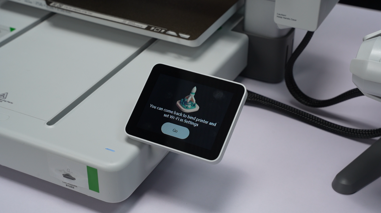
If you skipped the network process and Bambu Handy binding steps during the unboxing process, you can still connect and bind the printer to Bambu Handy in the settings page after the printer calibration is completed.
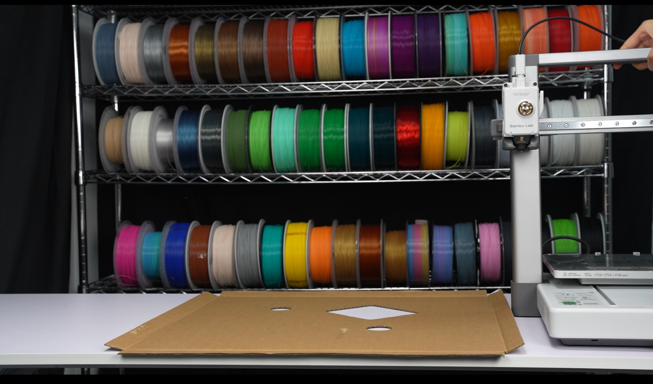
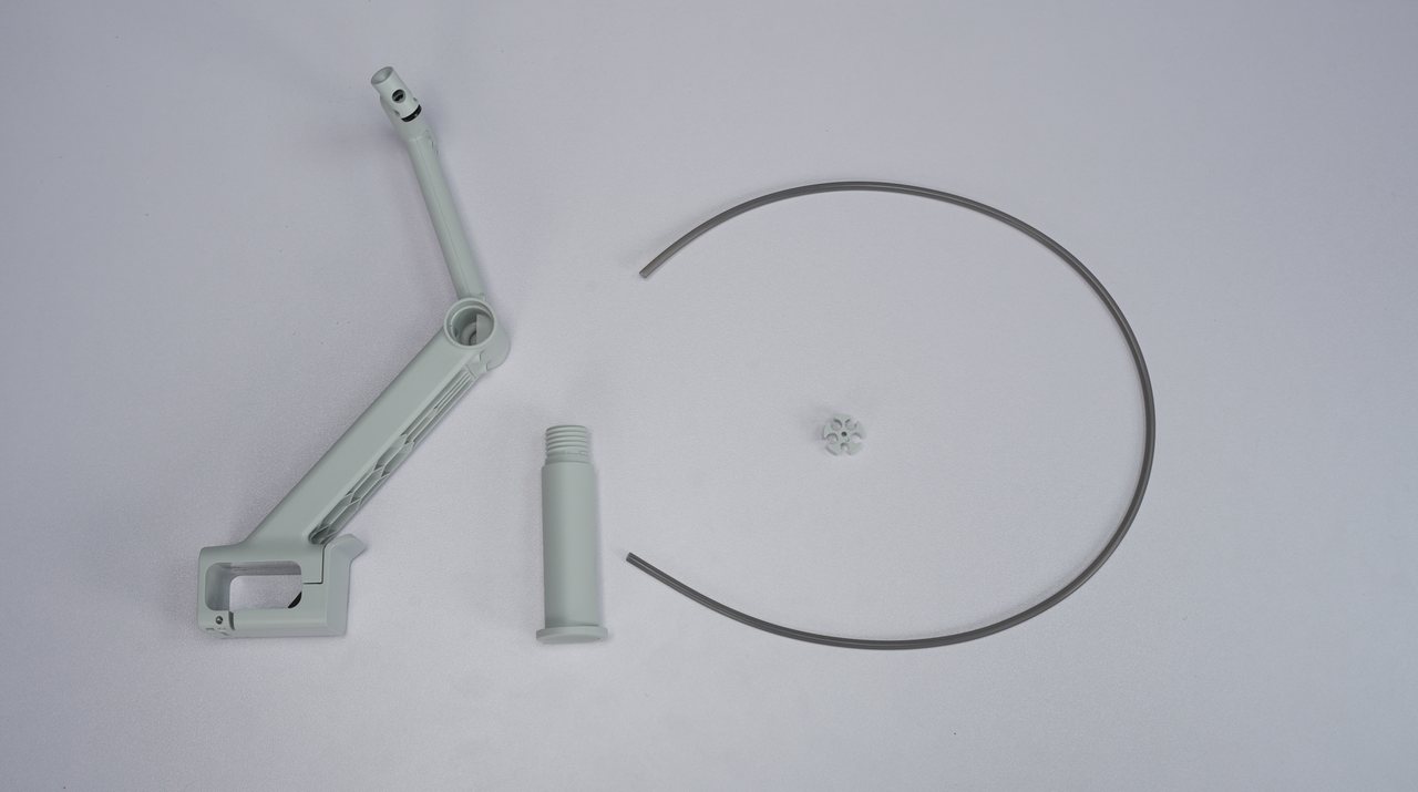
¶ Appendix: Installing the External Filament Spool Holder and Start the first print with A1
If you want to use an external spool, you can refer to the following steps to install the spool holder, PTFE tube, and filament spool.
If you are exclusively using the AMS lite for printing, you can choose whether to install the spool holder.
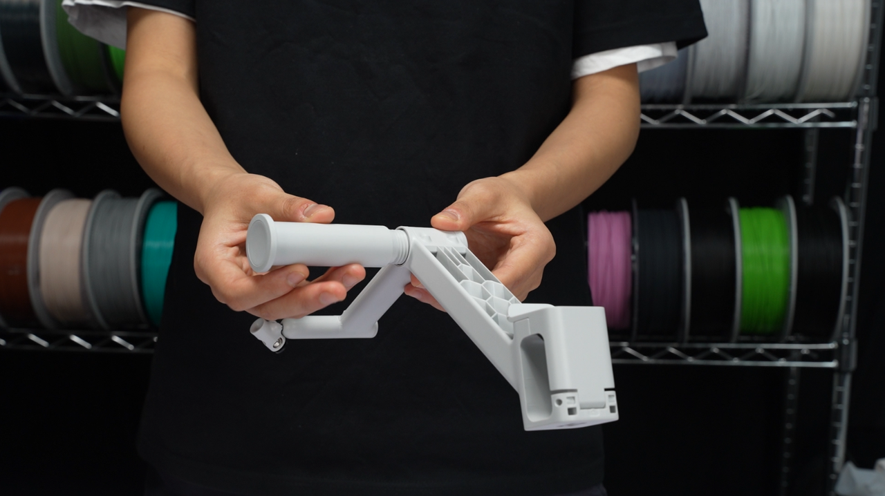
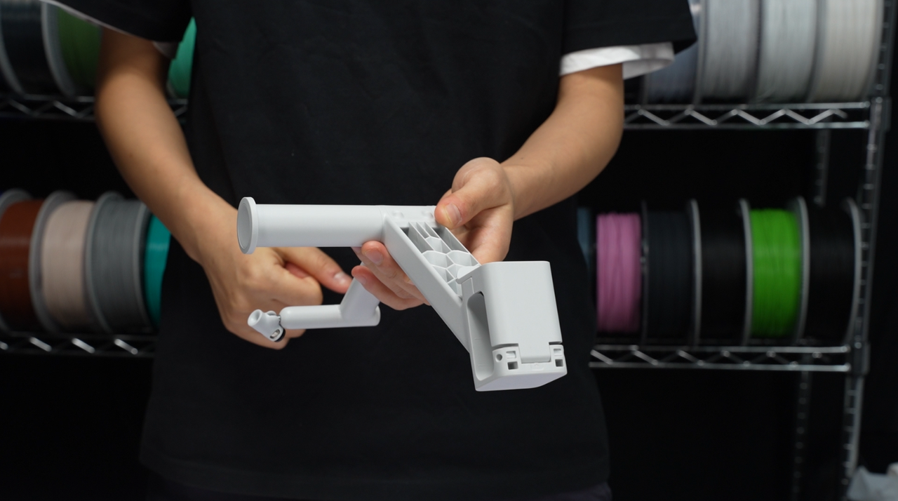
Screw the support shaft into the main body of the spool holder.
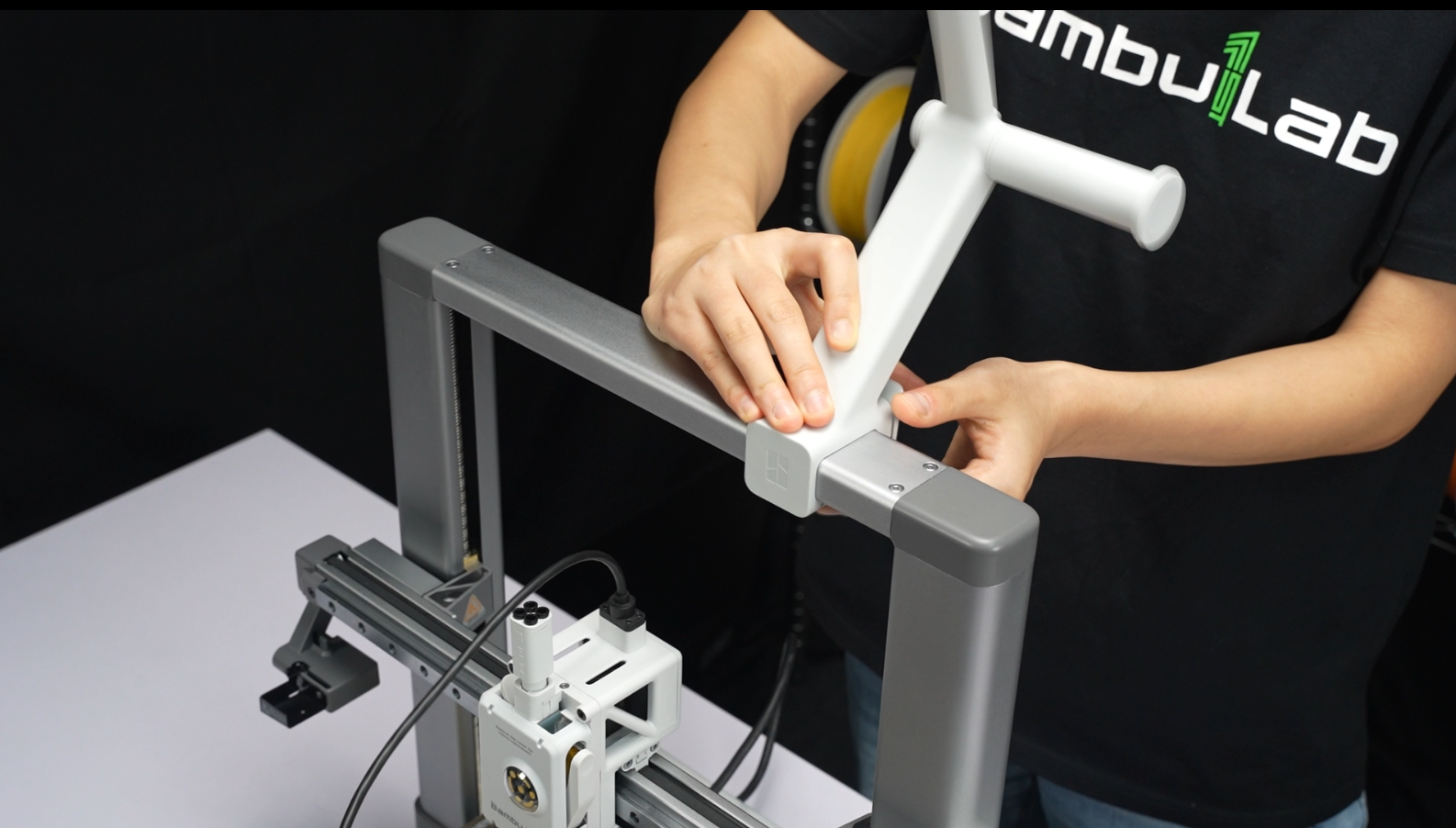
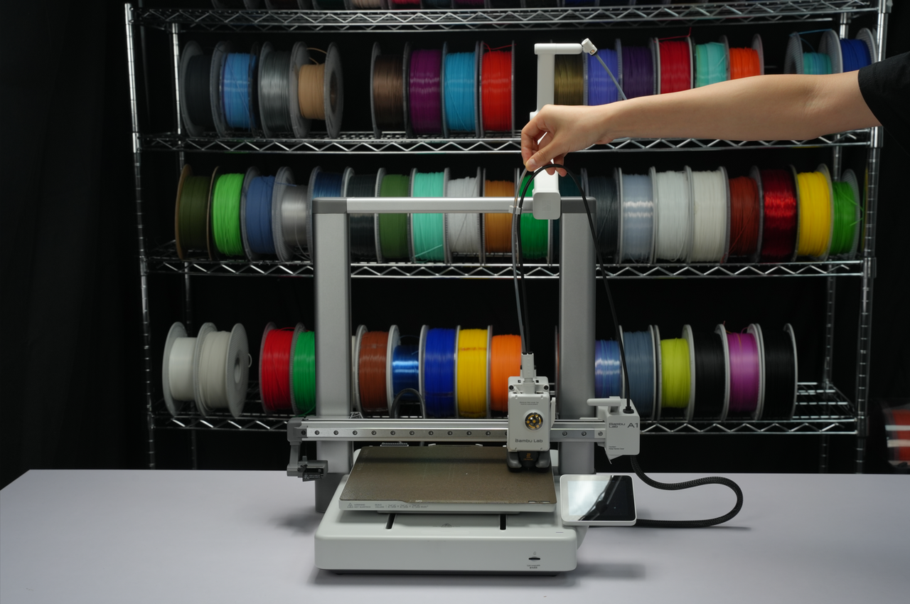
¶ 2. Attach the spool holder to the crossbeam of the frame, with the side featuring the Bambu Lab logo facing forward.
Installing the bracket in the middle right of the beam, close to the right side beam, is recommended.
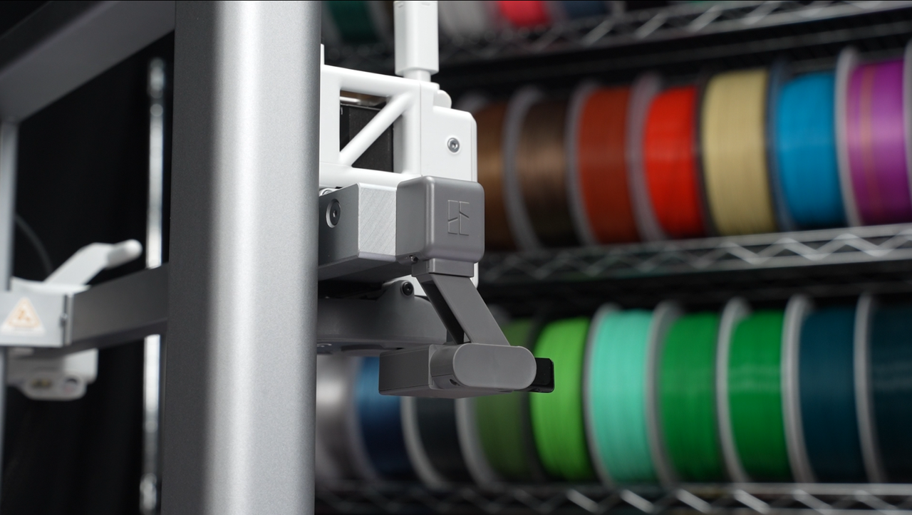
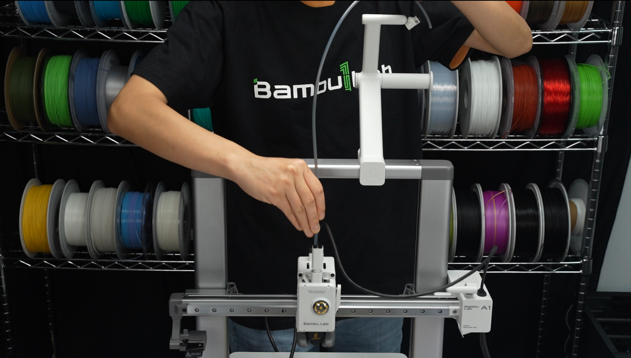
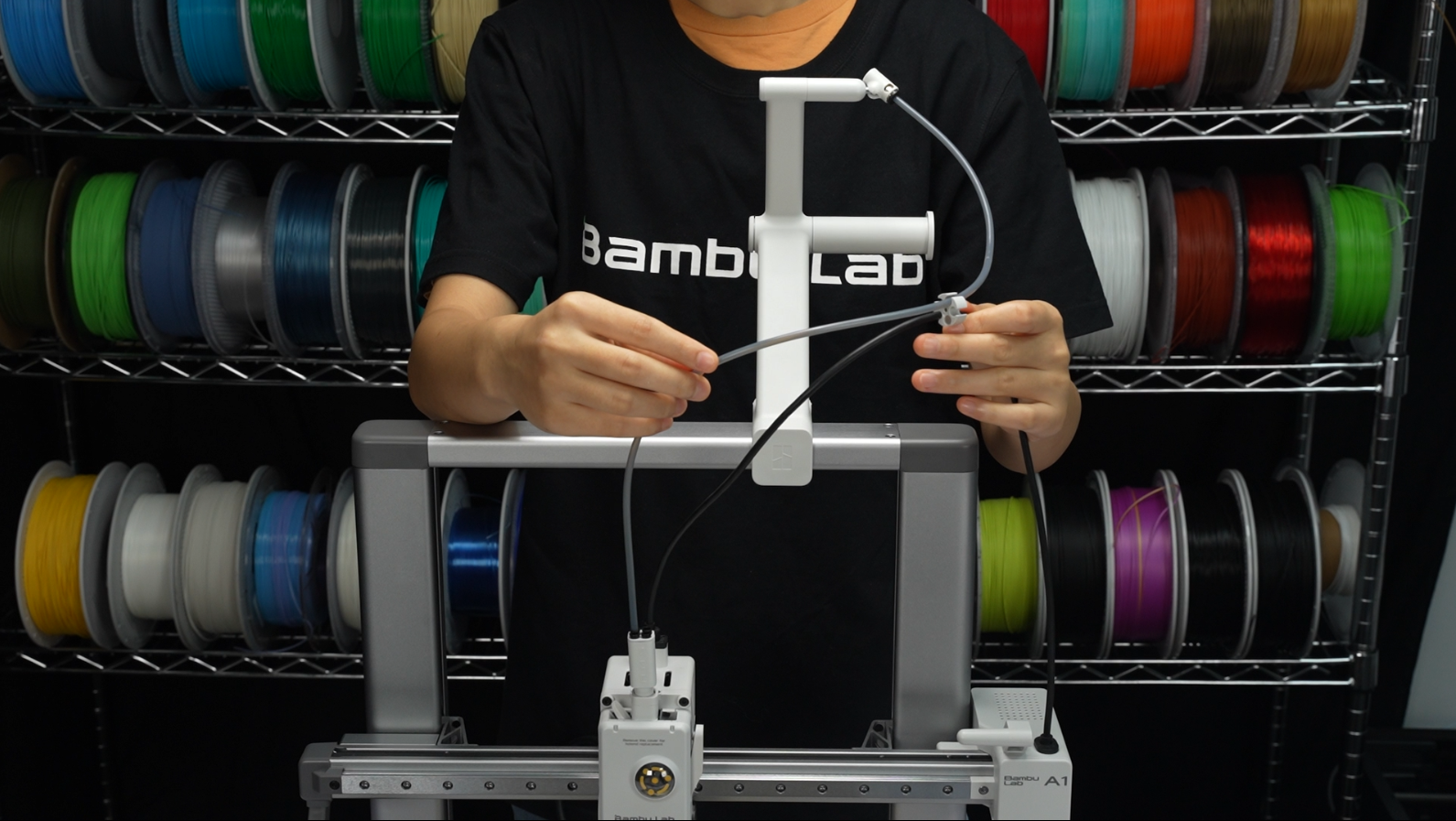
¶ 3. As shown in the picture, use the shortest PTFE tube to connect the filament inlet of any toolhead. The filament will be fed through this PTFE tube.
¶ 4. Install the cable organizer. Insert the black cable into the small hole of the organizer and insert the PTFE tube into any of the larger holes.
The optimal position for the organizer is to align the edge of the hub with the lower edge of the beam once it comes into contact with the hot end and heatbed. This is because, at this position, the likelihood of the Type-C interfering with the Z-axis column is minimized, thus avoiding any disruption to the Type-C connection.
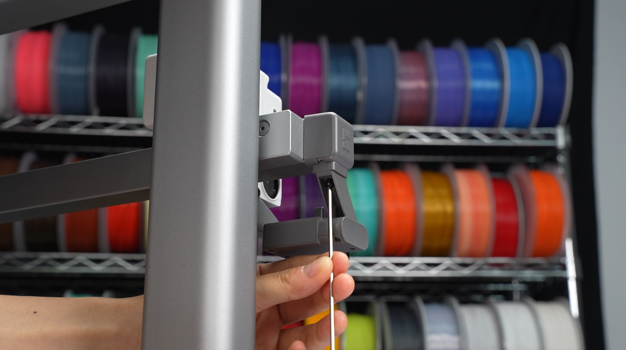
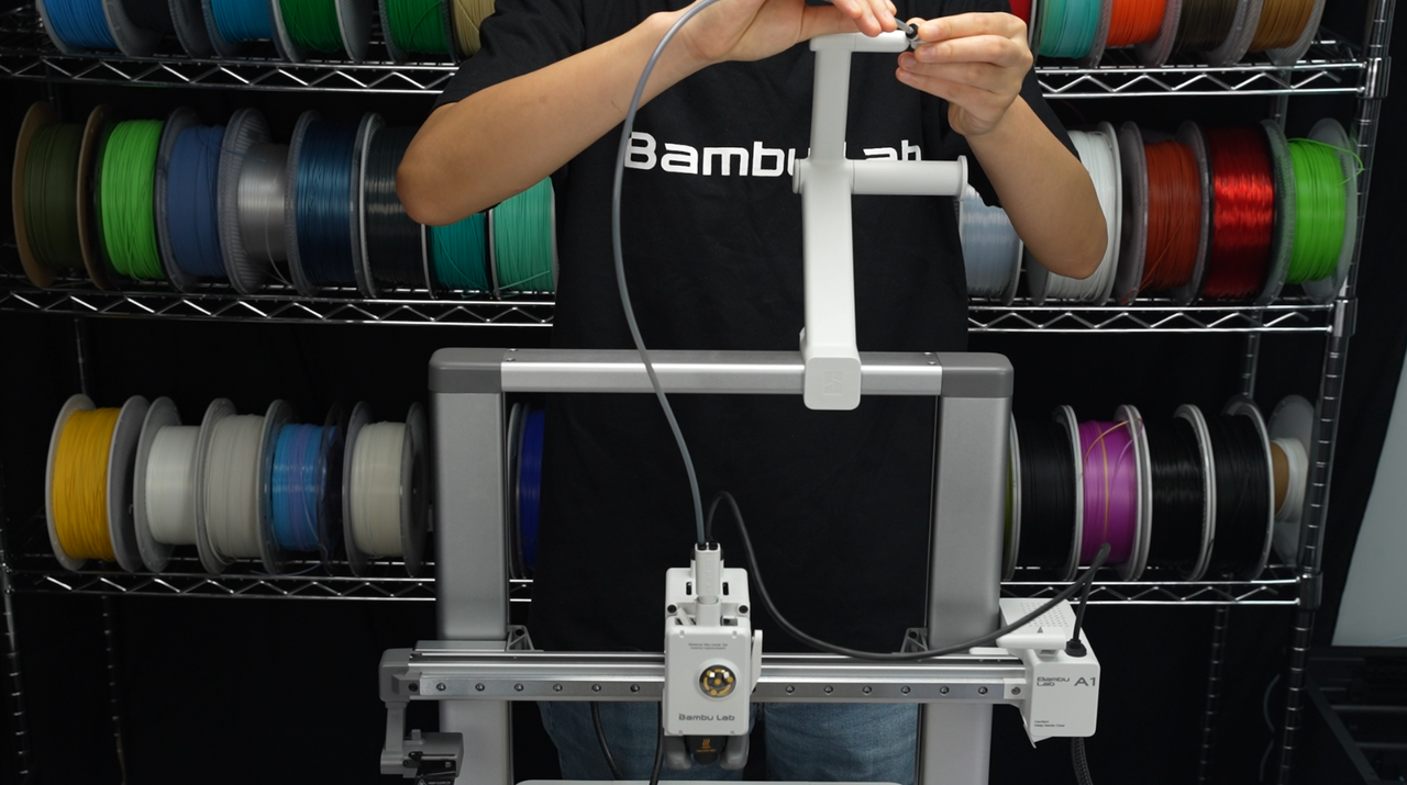
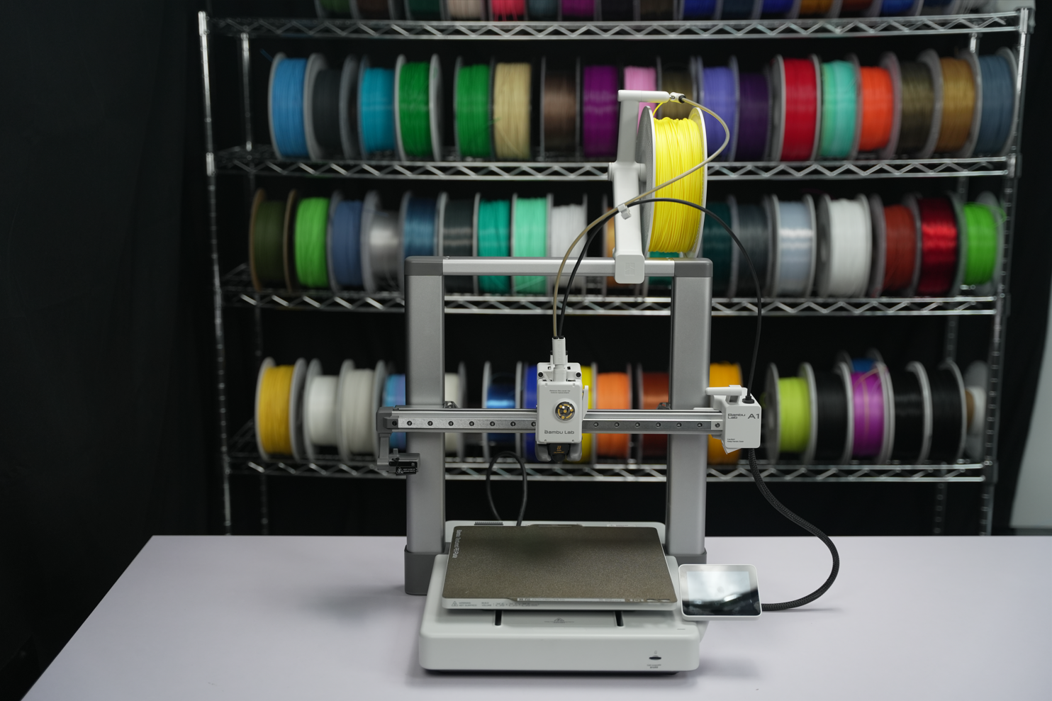
Hang the filament spool on the filament spool holder and then feed the filament into the PTFE tube.
We hope the detailed guide provided has been helpful and informative.
To ensure a safe and effective execution, if you have any concerns or questions about the process described in this article, we recommend submitting a technical ticket regarding your issue.
Please include a picture or video illustrating the problem, as well as any additional information related to your inquiry.
.png)
.png)
.png)
.png)