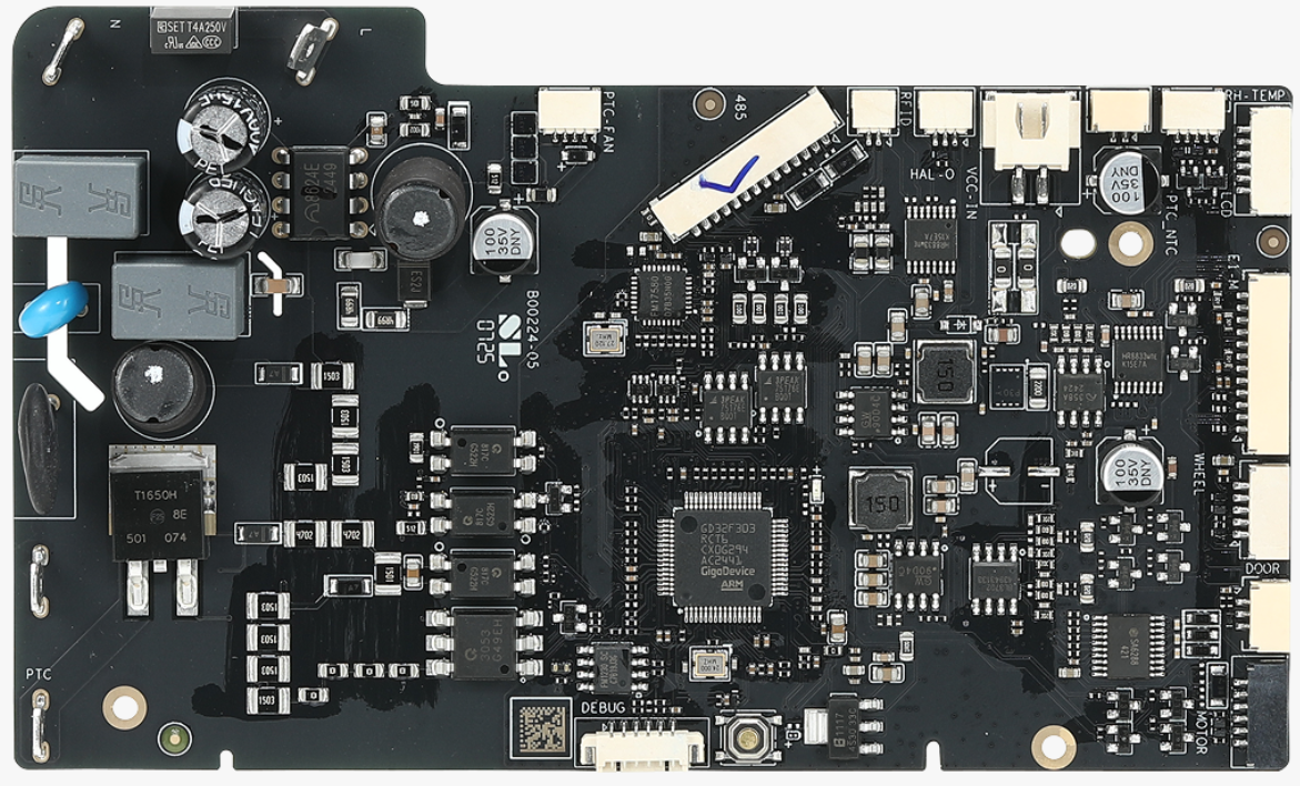
Central to the operation of the AMS is the AMS HT Motherboard, a vital component responsible for managing communication between sensors, motors, heaters, and the printer itself. If you suspect the unit has issues, you may need to disassemble it to inspect, clean, replace, or troubleshoot the motherboard. Performing this process correctly is crucial to prevent damage to delicate components. This detailed wiki guides you through the safe disassembly and reassembly of the AMS HT motherboard, providing clear instructions and practical tips.
¶ Tools and Materials Needed
Before starting, ensure you have the following:
- Hex Wrench for removing the screws
- Container to keep screws organized
- Replacement AMS HT motherboard (if applicable): You can get one on Bambu Lab store.
The disassembly process involves removing the outer cover, accessing internal modules, and detaching the motherboard.
¶ Safety Warning
It's crucial to power off the printer before performing any maintenance work on the printer and its electronics, including tool head wires, because leaving the printer on while conducting such tasks can cause a short circuit, which can lead to additional electronic damage and safety hazards.
When you perform maintenane or troubleshooting on the printer, you may be required to disassemble some parts, including the hotend. This process can expose wires and electrical components that could potentially short circuit if they come into contact with each other or with other metal or electronic components while the printer is still on. This can damage the electronics of the printer and cause further damage.
Therefore, it's essential to switch off the printer and disconnect it from the power source before doing any maintenance work. This will prevent any short circuits or damage to the printer's electronics. By doing so, you can avoid potential damage to the printer's electronic components and ensure that the maintenance work is performed safely and effectively.
¶ Disassembly
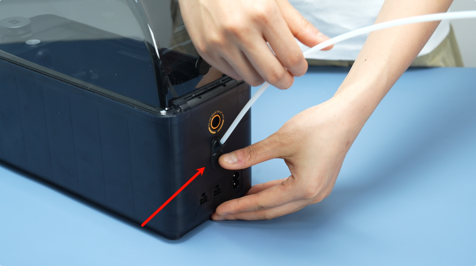
¶ Step 1: Disconnect the AMS HT Unit and Remove the PTFE Tube
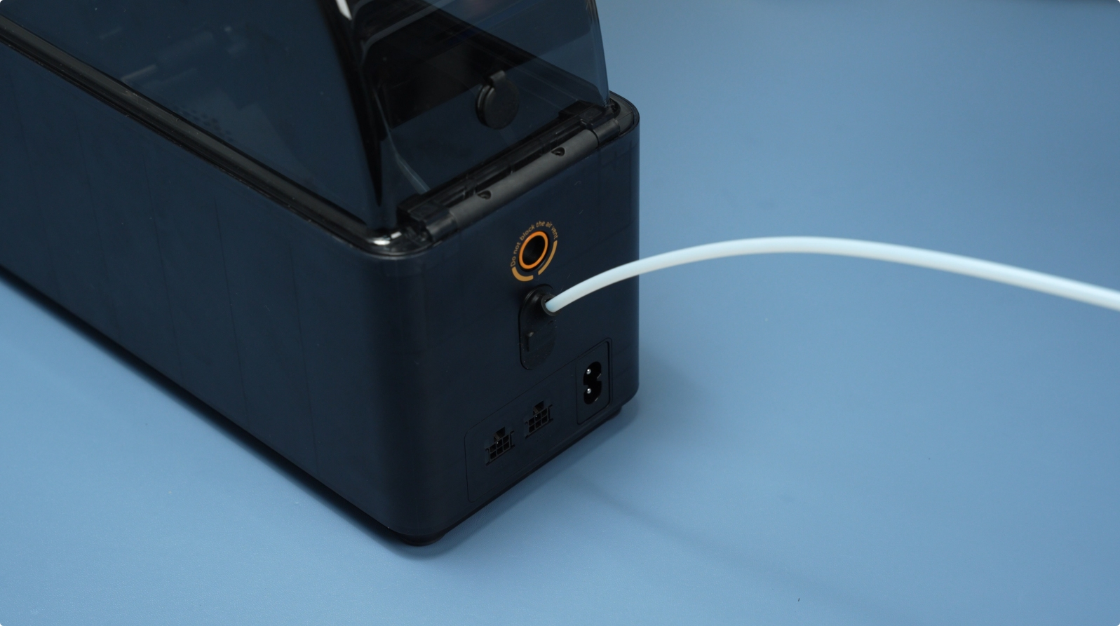
Press the PTFE tube release button located at the back of the AMS HT to unlock the connector, then gently pull out the PTFE tube.
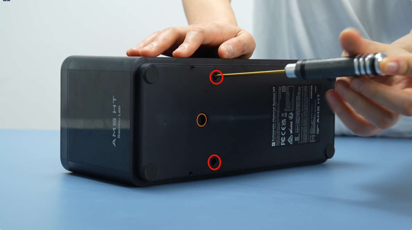
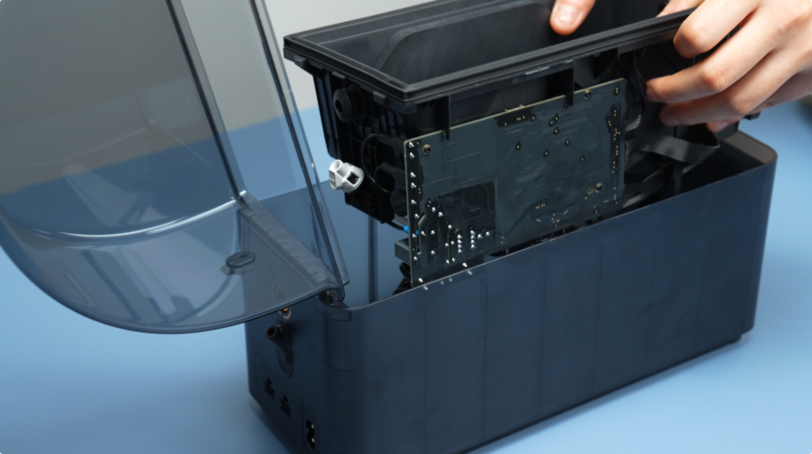
¶ Step 2: Remove the AMS HT Main Frame
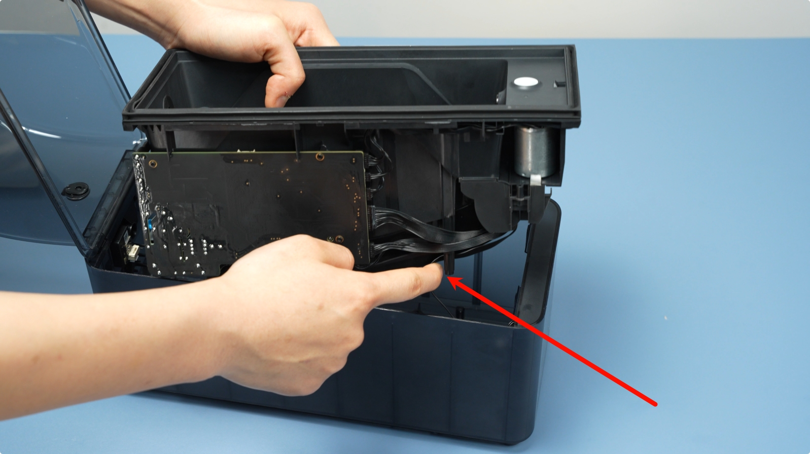
Remove the the two bottom screws (BT3X8) labeled at the bottom which help secure the lower section of the AMS housing. Then, lift the Main Frame Assembly Slowly Upward.
 |
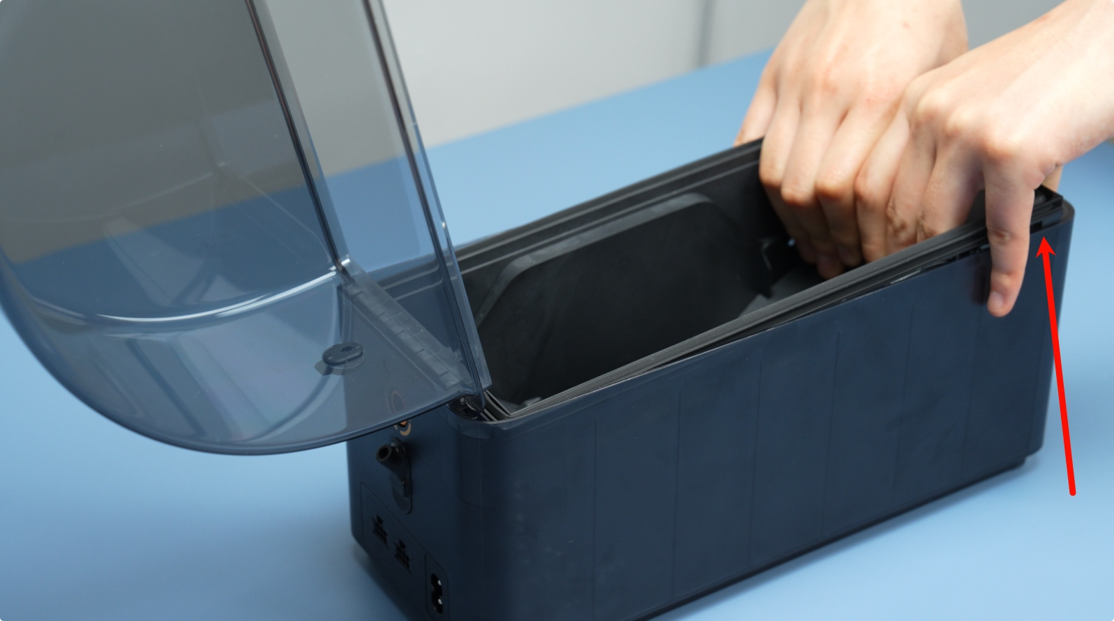 |
Make sure you do it gently, as there are cables connected to it, as shown below.
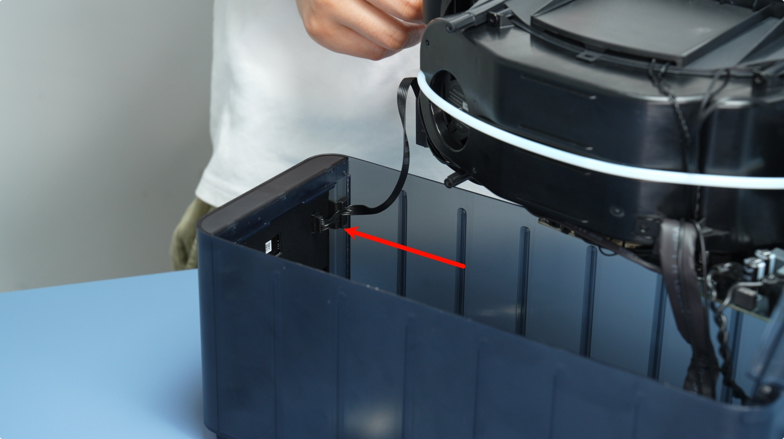
¶ Step 3: Removing the Cables and Connectors
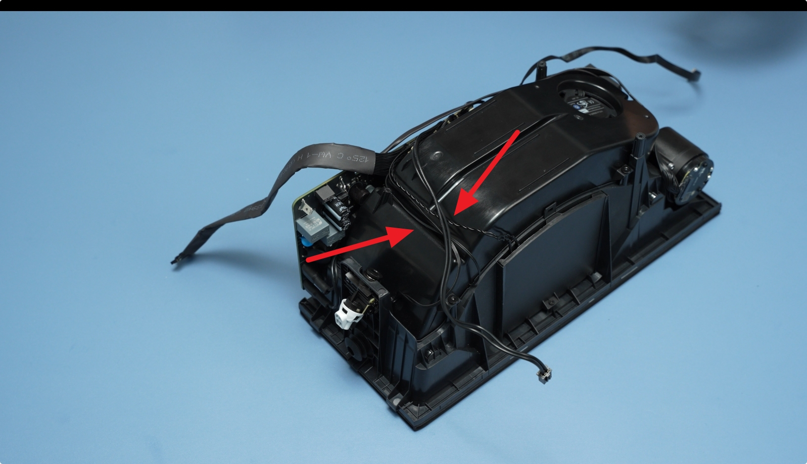
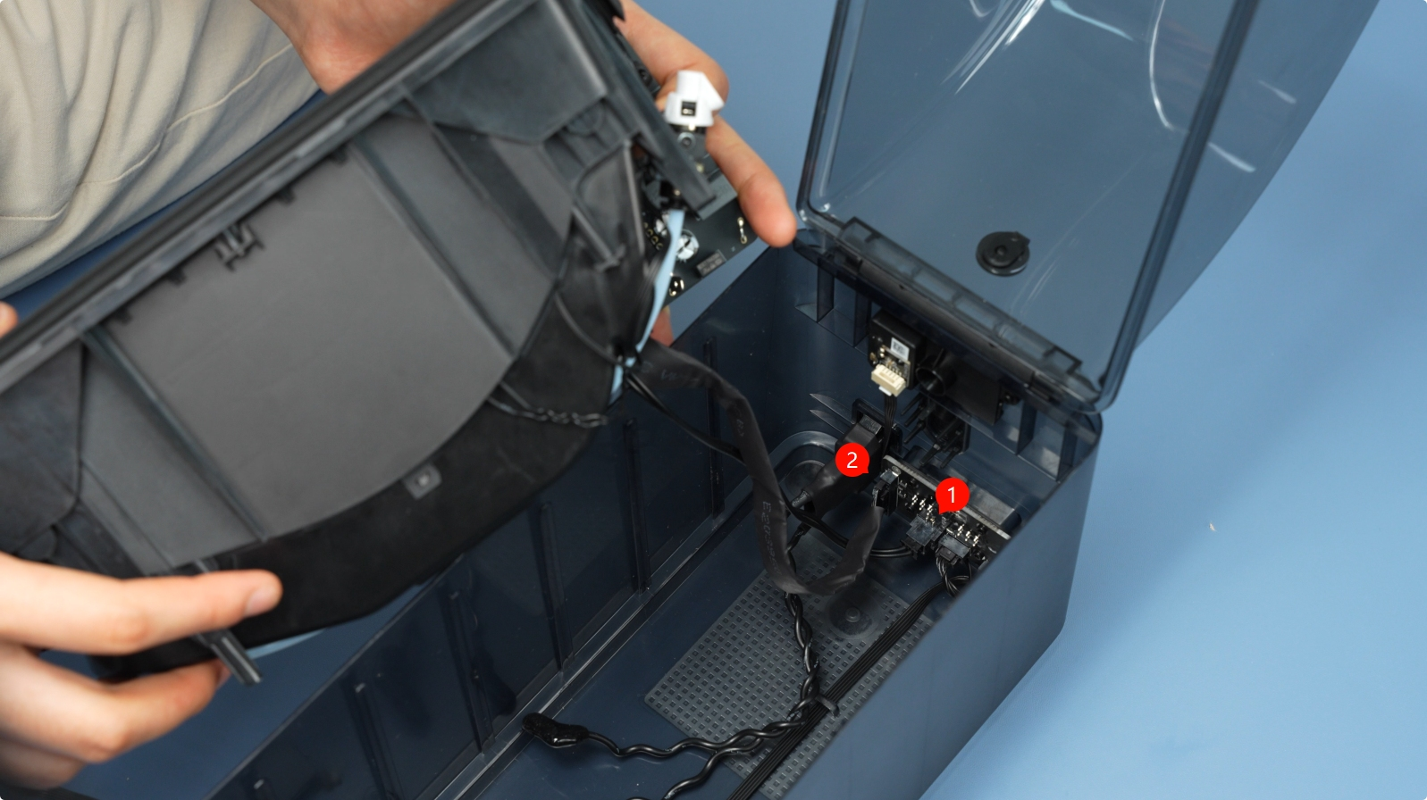
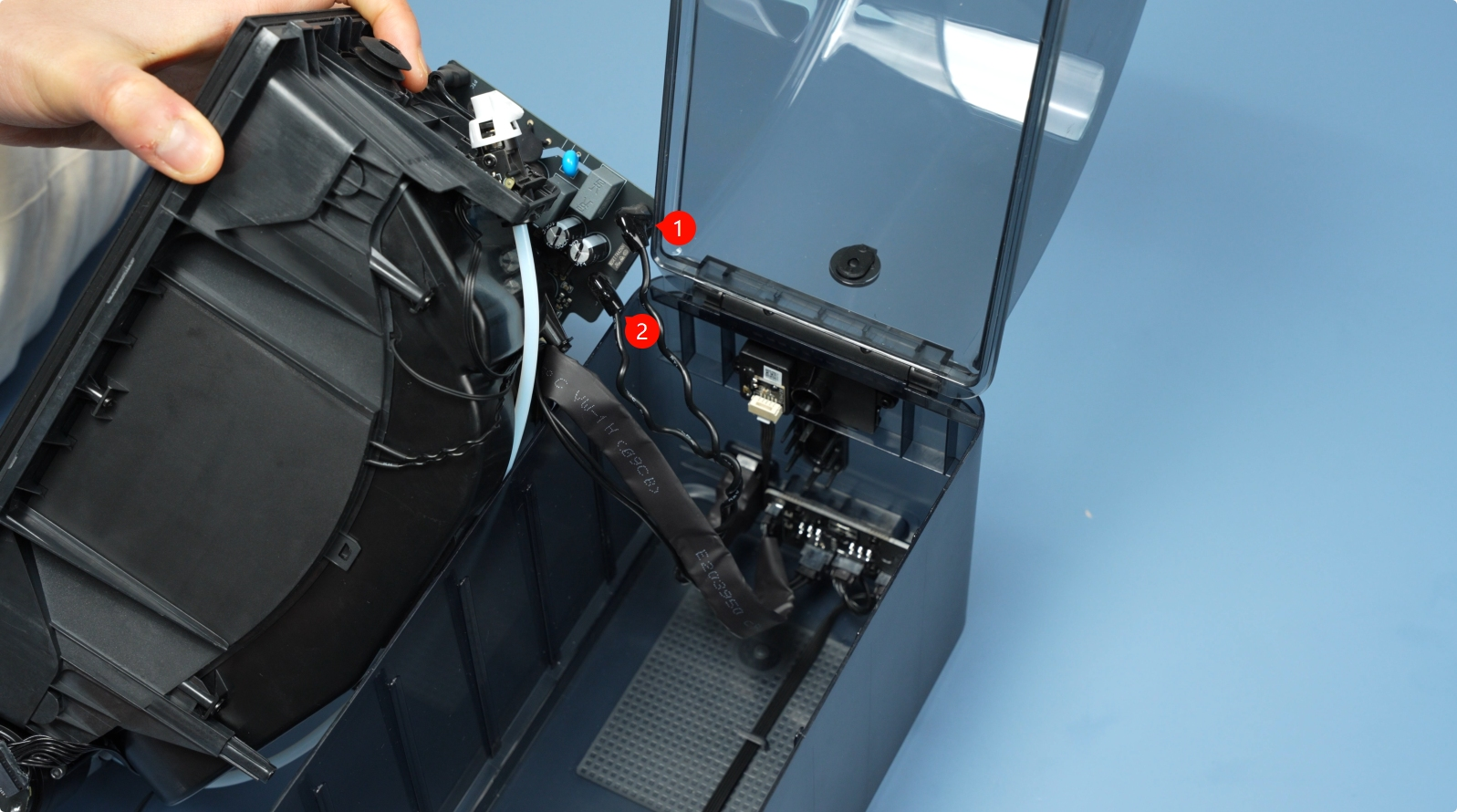
Release the Connector Latch, then unplug the cable connecting the front screen. Then, disconnect the signal and power cables, shown below.
 |
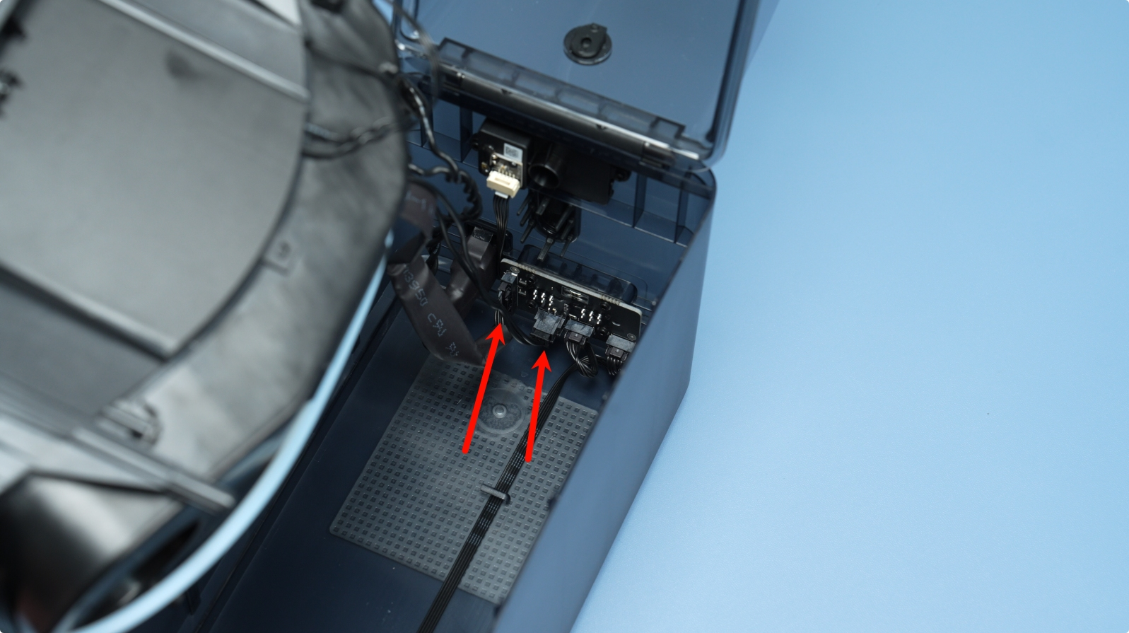 |
Hold them gently and remove them from their place. You pull out the connectors and not the wires to avoid breaking them.
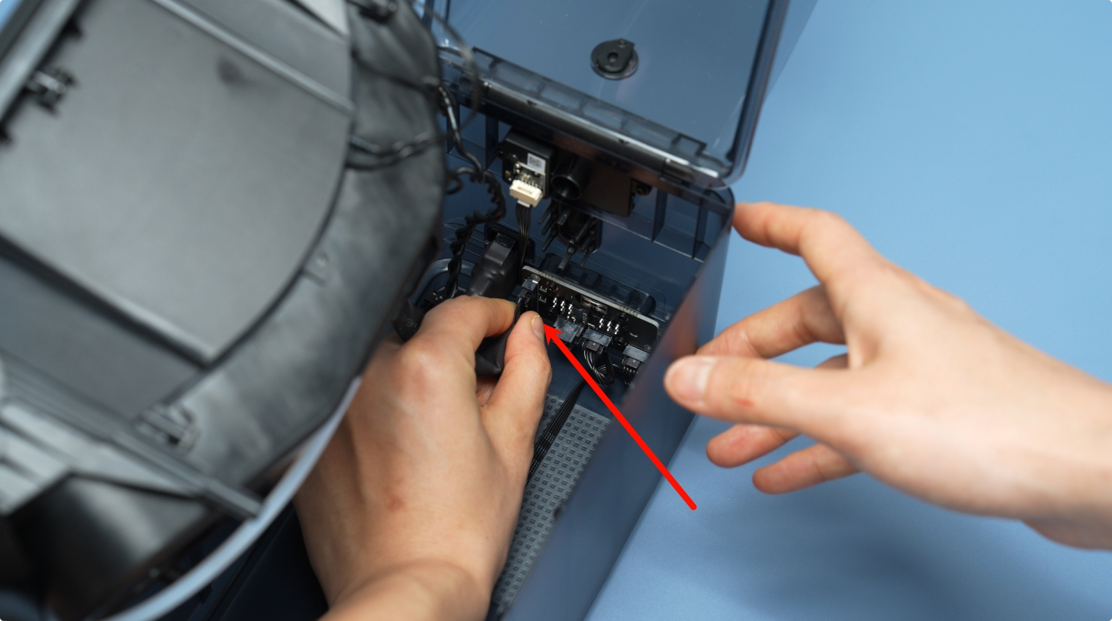
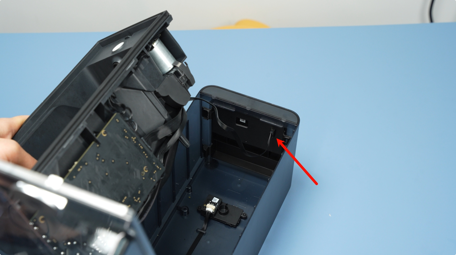
¶ Step 4: Remove the Power Socket-to-Mainboard Cable
The connector that links the power socket to the mainboard is shown below.
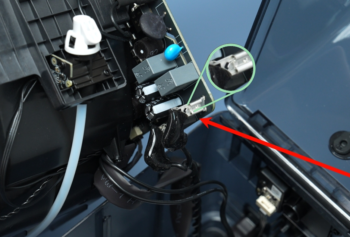
Press down on the unlock latch to release the locking mechanism that secures the cable in place. To remove it, press the unlock latch firmly to release the locking mechanism. Once the latch is disengaged, gently but steadily pull the connector out to disconnect the cable.
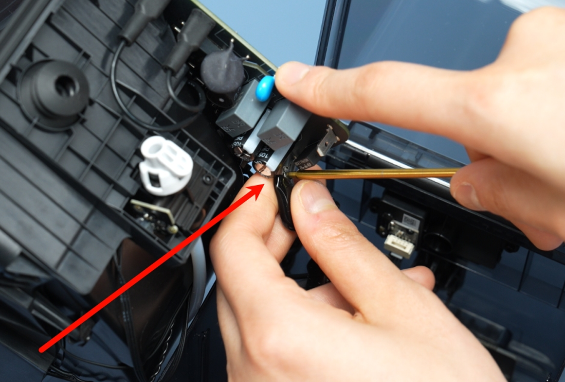
Avoid using excessive force to prevent damage to the connector pins or the mainboard.
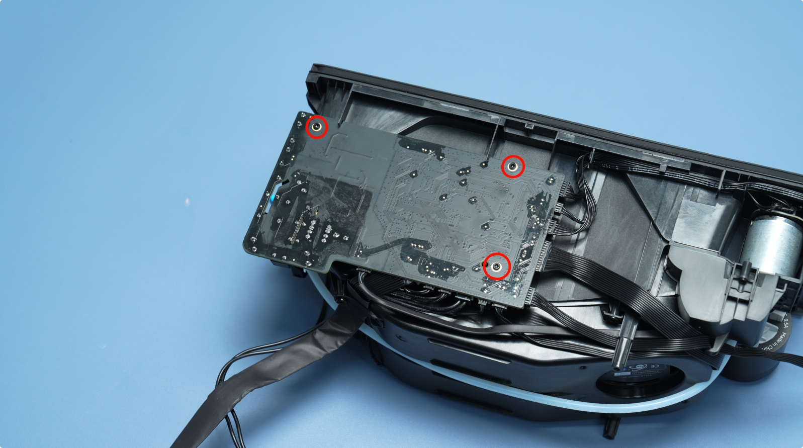
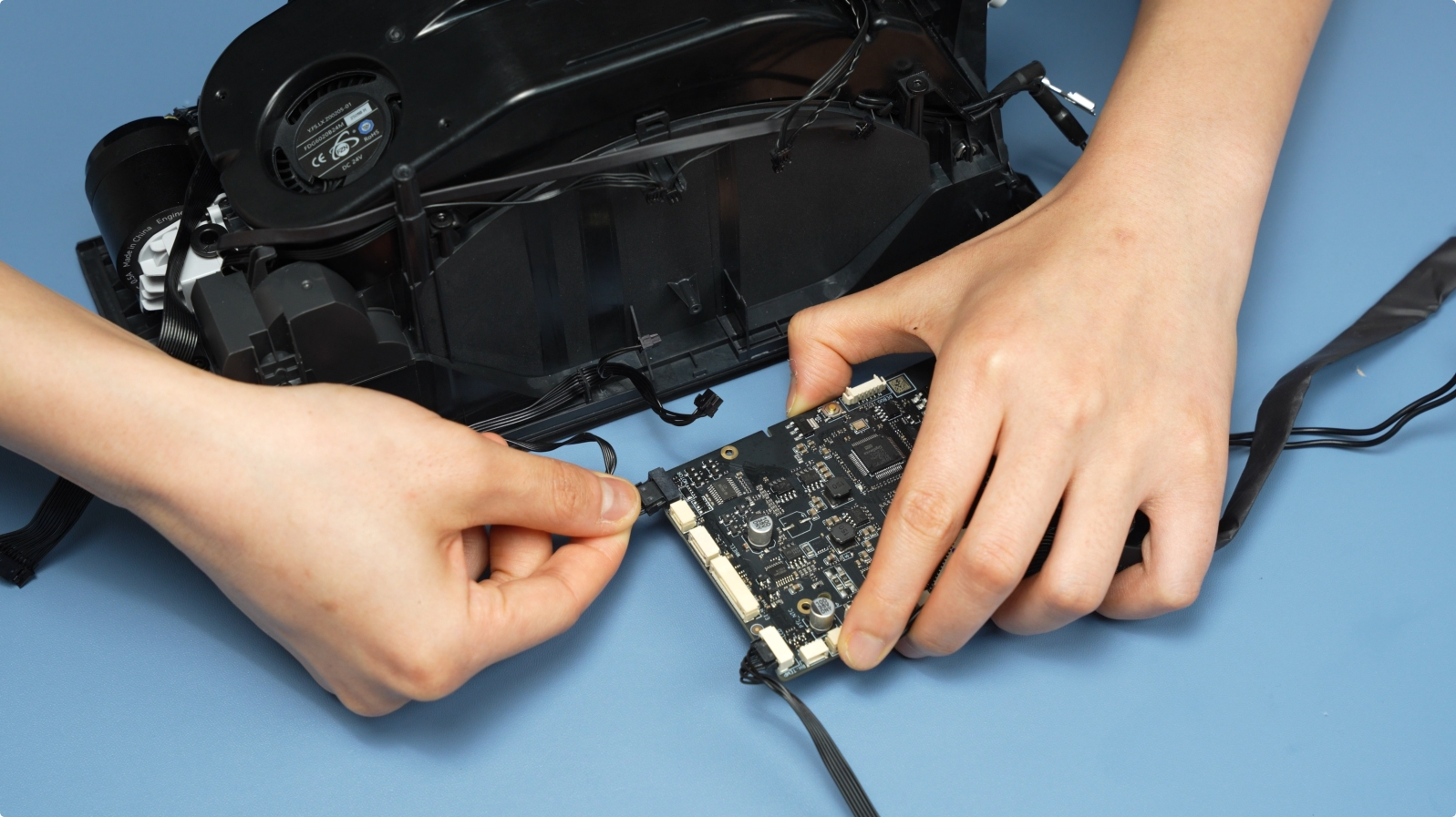
¶ Step 5: Removing the AMS HT Motherboard
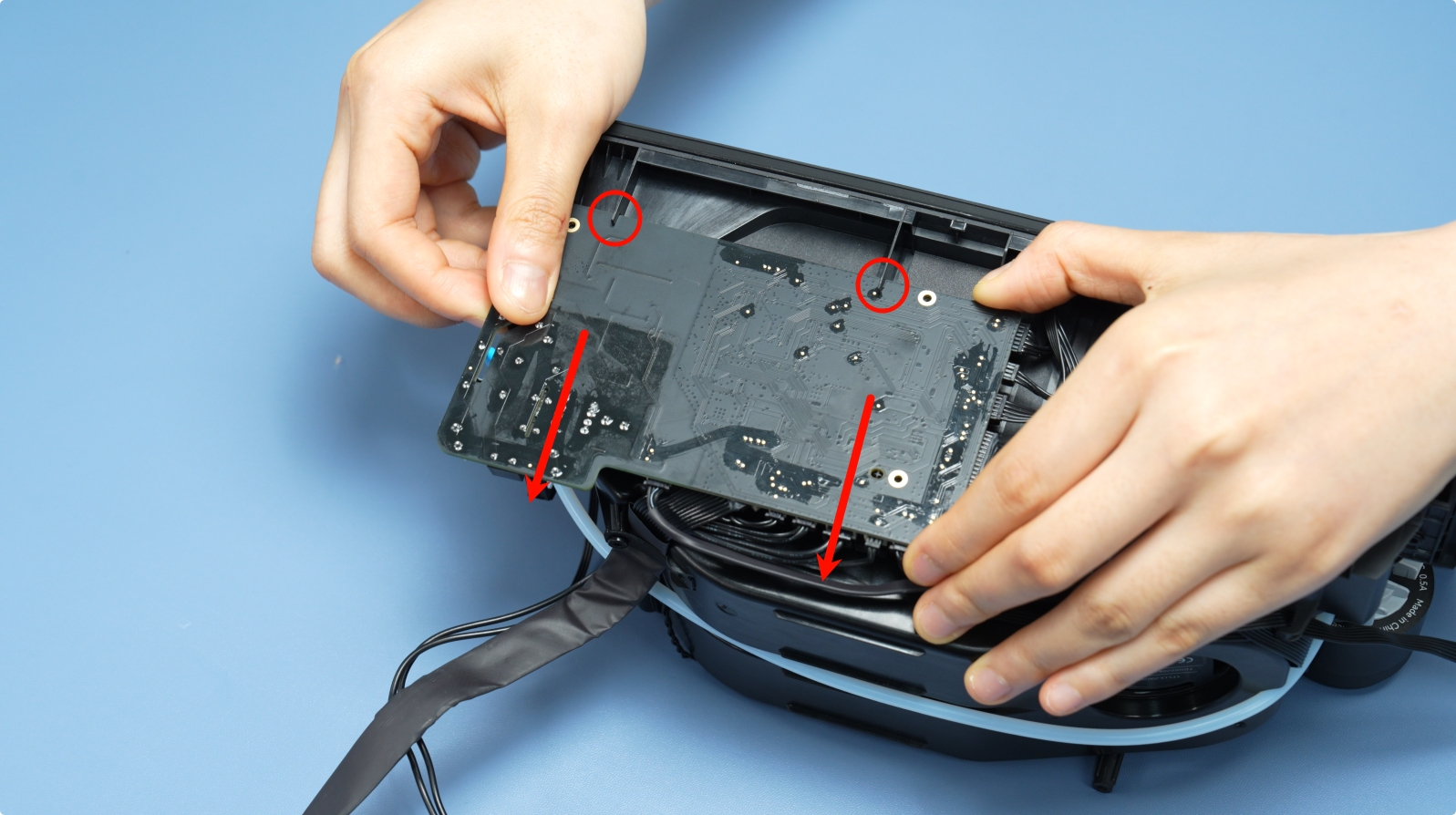
Start by removing the three screws that attach the motherboard to AMS HT. Next, gently slide the mainboard out of its slot, ensuring that you do not force it.
 |
 |
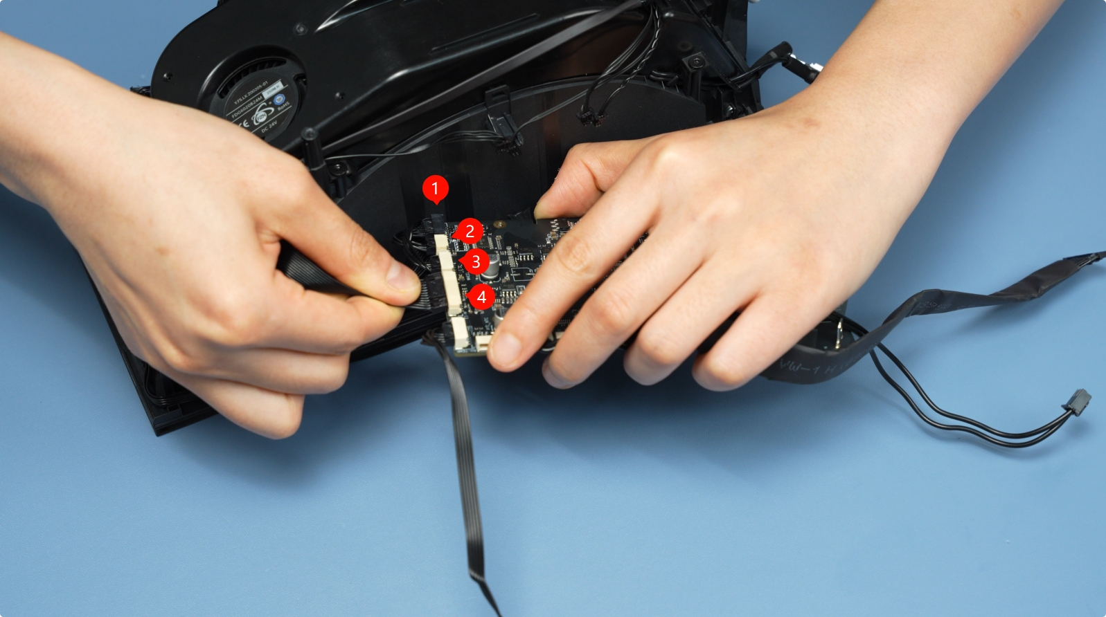
There are four cables connected to the mainboard that need to be disconnected. They are shown below.
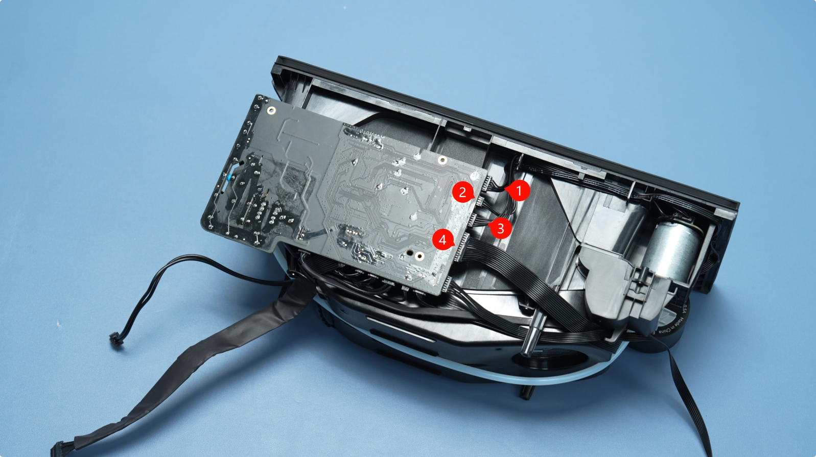
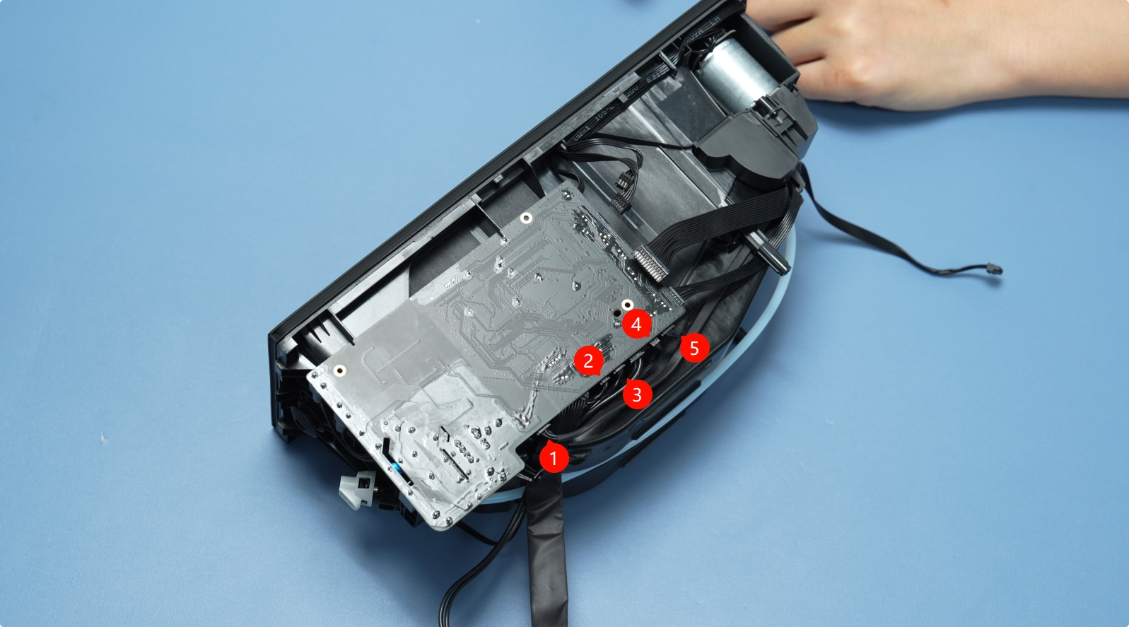
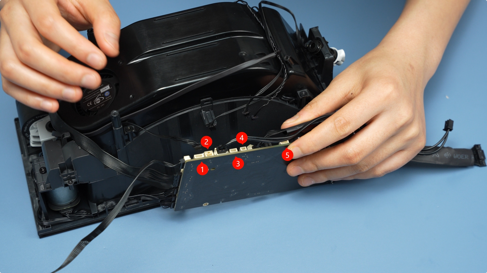
Gently pull each wire out by holding the connector itself, not the wires. Next, disconnect the five cables at the bottom. They are shown below.
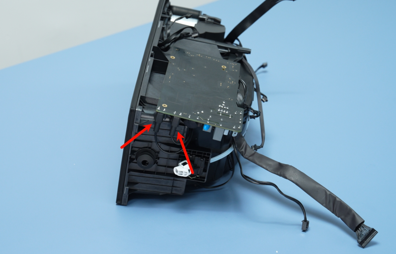
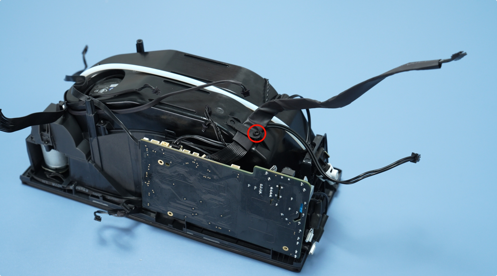
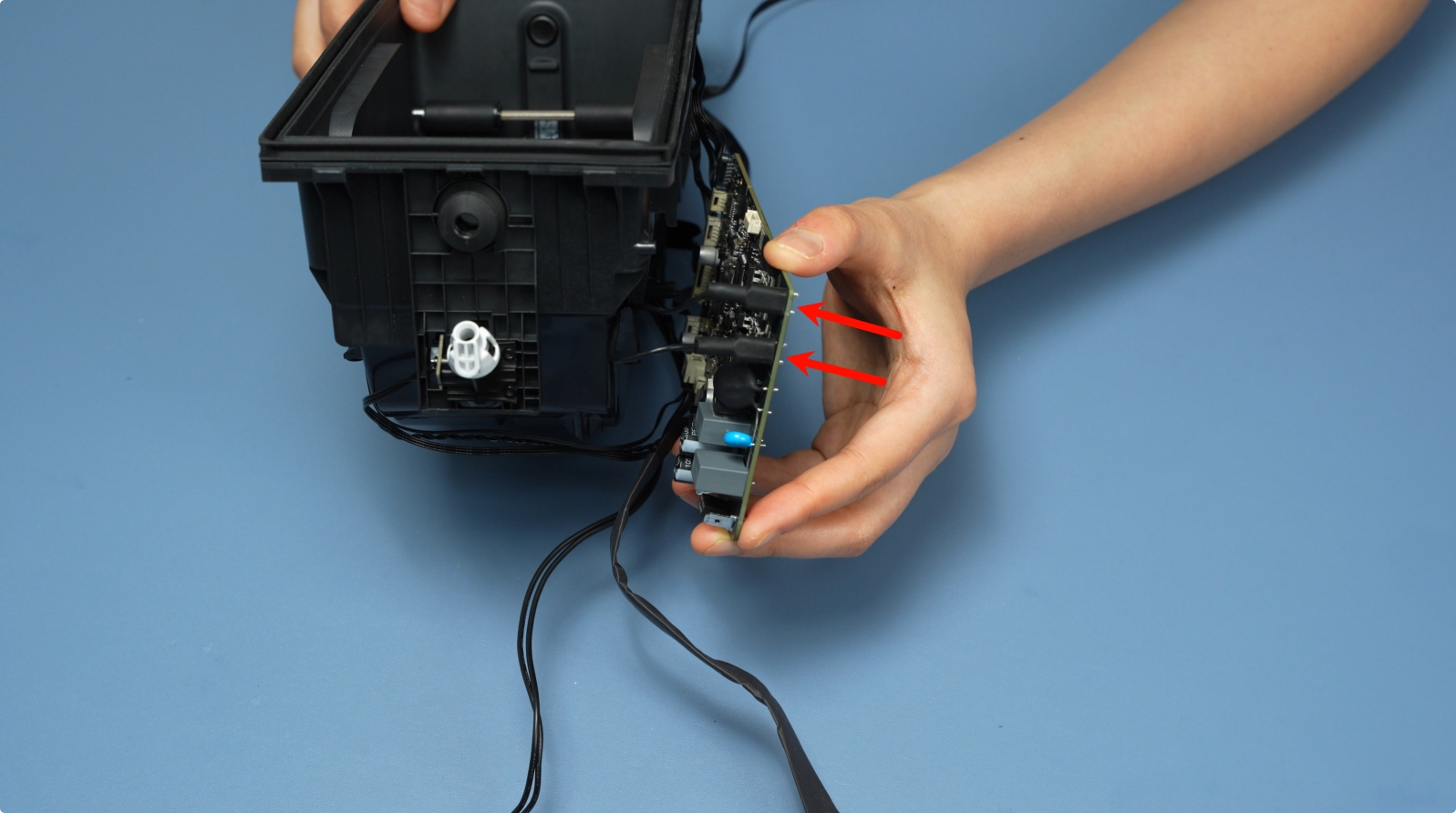
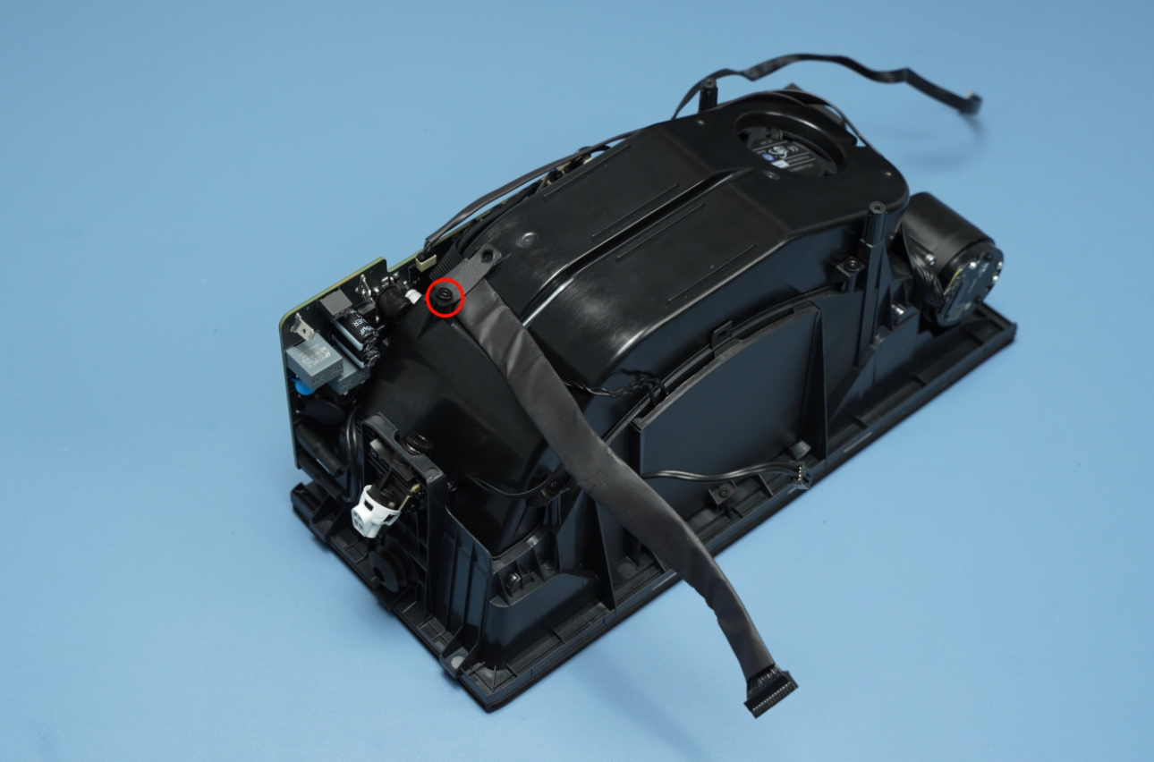
¶ Step 6: Disconnect the Heater Cable
First, press the latch to unlock the connector. Then, slide the insulation down to expose the connector. While continuing to press the latch, gently pull the connector out. As you do so, be careful not to tug on the wires directly.
 |
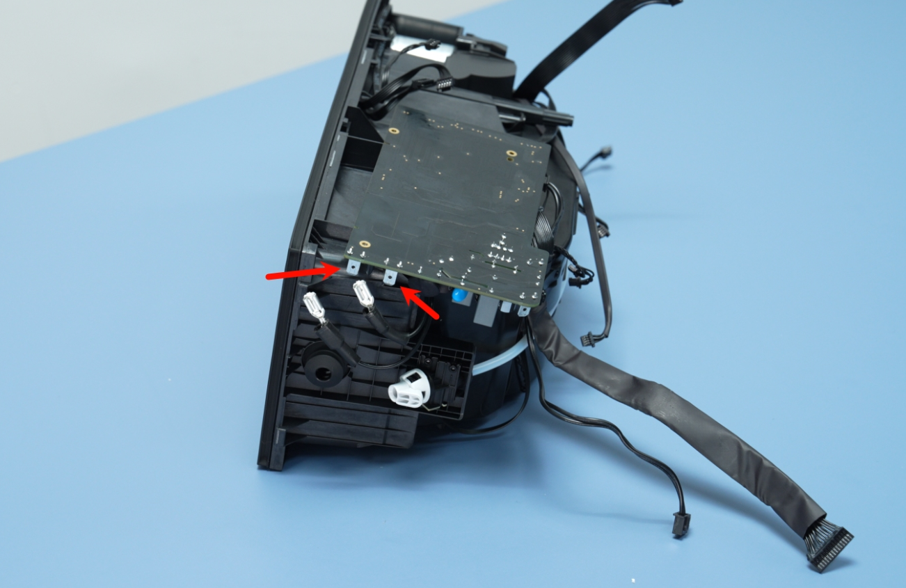 |
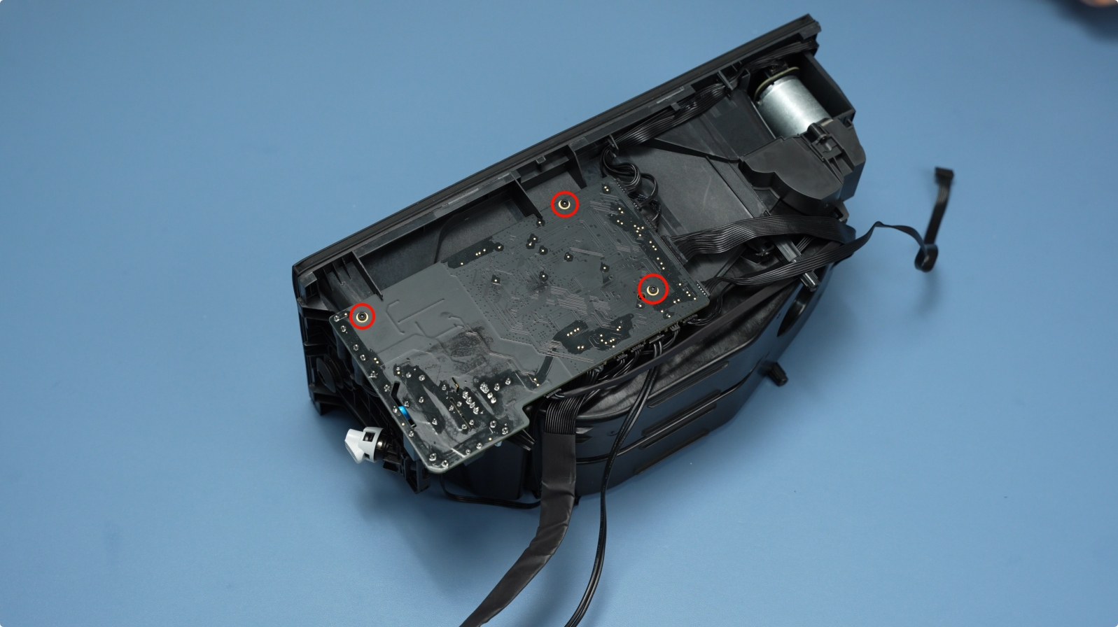
Remove the retainer screw that secures the mainboard in place. Once the screw is removed, carefully lift and remove the mainboard from its slot, ensuring that you do not bend or damage any surrounding components during the process.
 |
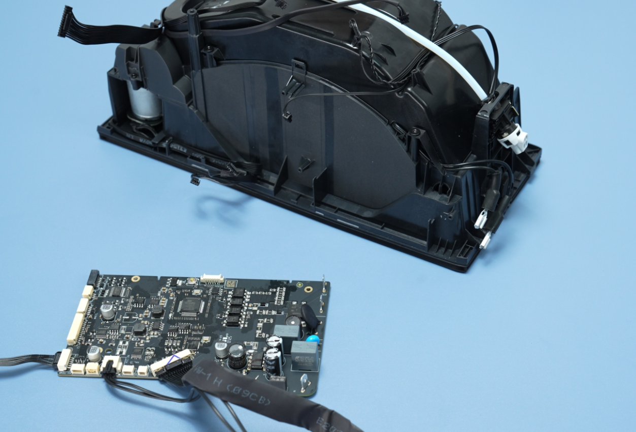 |
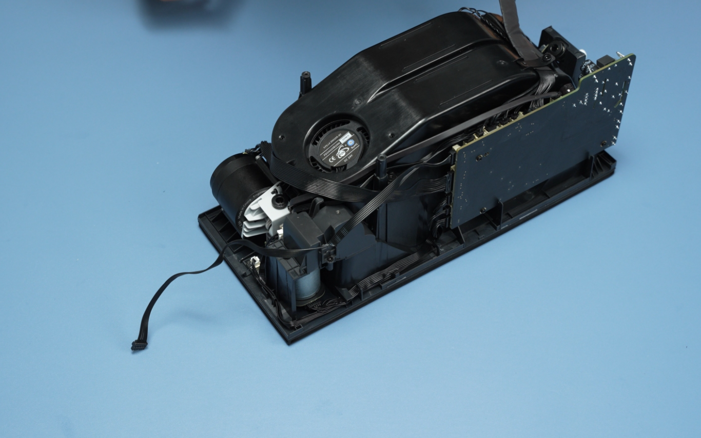
We have successfully removed the motherboard from the AMS HT. Below are the various parts of the part.
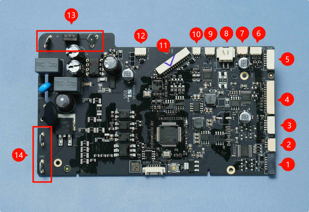
1. Filament Retraction Motor |
2. Lid Status Hall Sensor |
3. Odometer Board |
4. 3520 AMS Internal Assist Motor |
5. LCD Screen |
6. Temperature & Humidity Sensor |
7. Heating Unit Thermistor |
8. Mainboard Power Connector |
9. Feeder Hall Sensor Assembly |
10. RFID Coil |
11. Mainboard Communication Connector |
12. Heating Unit Fan |
13. Mainboard AC Input |
14. Heating Unit AC Input |
Before starting reassembly or replacing the motherboard, perform the following detailed checks:
Check for burnt components: Look for blackened areas, melted plastic, or scorched circuit traces. These signs may indicate a short circuit or component failure that could affect overall performance. If you discover any burnt item, you should contact customer support before installing the board and turning on the device. Otherwise, the new board could be damaged right after turning on the unit
Inspect connectors for damage: Gently check each connector for looseness or physical breakage.
If you have a new one and would like to replace the existing one. Align it carefully with the same orientation as the original. Next, follow the steps below to properly assemble.
¶ Assembling
¶ Step 1: Connect the Cables
Before securing the mainboard with screws, connect the four side cables to their corresponding ports. Ensure that you insert them in the right position.
The interfaces shown above correspond to the following:
- Filament Retraction Motor
- Lid Status Hall Sensor
- Odometer Board
- 3520 AMS Internal Assist Motor
After inserting the above four, next connect the other five cables in sequence:
- Temperature & Humidity Sensor
- Thermistor
- Feeder Hall Sensor Assembly
- RFID Coil
- Heating Unit Fan
All the wires are different, and each one has a unique connector, so it's not possible to insert a wire into the wrong place.
After connecting all the cables to the mainboard, inspect each one to ensure it is securely attached.
¶ Step 2: Connect the Heater Cable
Connect the heater cable by aligning it with its port and gently pushing it in until it clicks into place, ensuring a firm and secure connection. The wire order does not matter here. Once connected, slide the insulation sleeve back over the connector.
¶ Step 3: Insert the Motherboard into its Place
Insert the mainboard carefully into its designated slot, making sure it is properly aligned with the mounting points and connectors. Once in place, secure it by tightening the three screws.
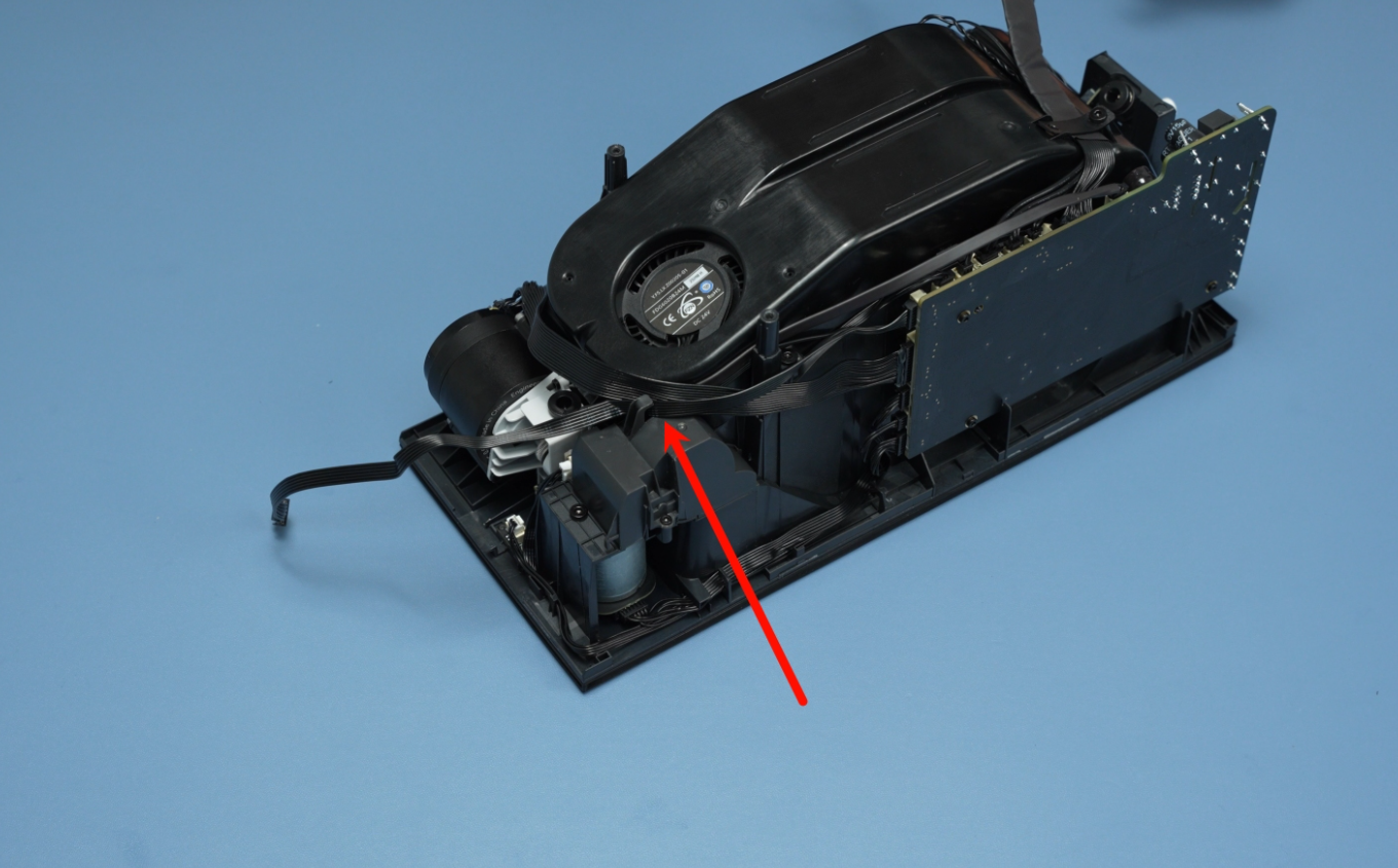
¶ Step 4: Organize the Rear Cables
Place the four thin cables neatly at the bottom of the designated cable channel or space. Once they are laid flat and aligned, position the thicker mainboard communication cable directly on top of them, as shown below.
Then, secure the entire bundle with the retainer screw to hold the cables firmly.
¶ Step 5: Organize the Front Cables
Rotate the AMS HT unit 180° to access the front side.
Then, carefully organize the front cables by guiding them into the designated cable channel.
Ensure each cable is laid flat and follows the channel path without twisting or crossing over others.
The next step is to assemble the AMS HT cables and the main frame.
¶ Step 6: Assembling the AMS HT Main Frame
Start by connecting the PTFE tube by inserting one end into the feeder and the other end into the outlet.
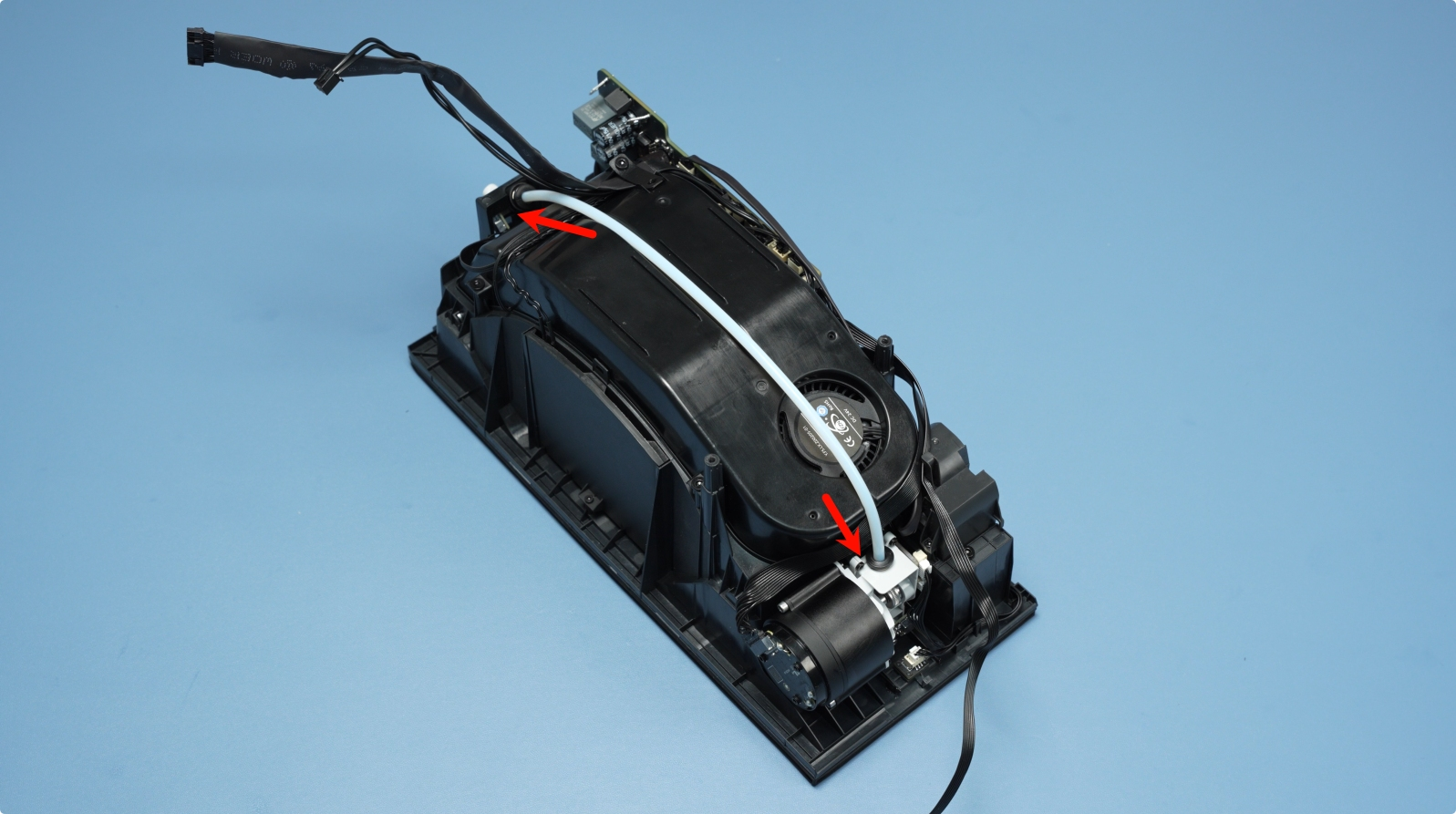
Next, connect the two remaining cables to the mainboard, starting with the 14-pin mainboard communication cable. Align the connector carefully and press it firmly into its corresponding port until it clicks into place. Next, attach the 2-pin mainboard power cable, ensuring correct orientation before gently pressing it in.
¶ Step 7: Connect the Power Socket Cable
Connect the power socket cable to the mainboard by aligning the connector and pressing it firmly into the appropriate port until it is fully seated.
Once the connection is secure, slide the insulation sleeve back over the connector.
¶ Step 8: Connect the Front Screen Cable
Carefully align the front screen cable with its connector and press it into place until it clicks securely into position.
Once connected, route the cable neatly along the designated channel. Next, use your fingers to gently hook and hold the protruding cables, keeping them clear of any mounting areas.
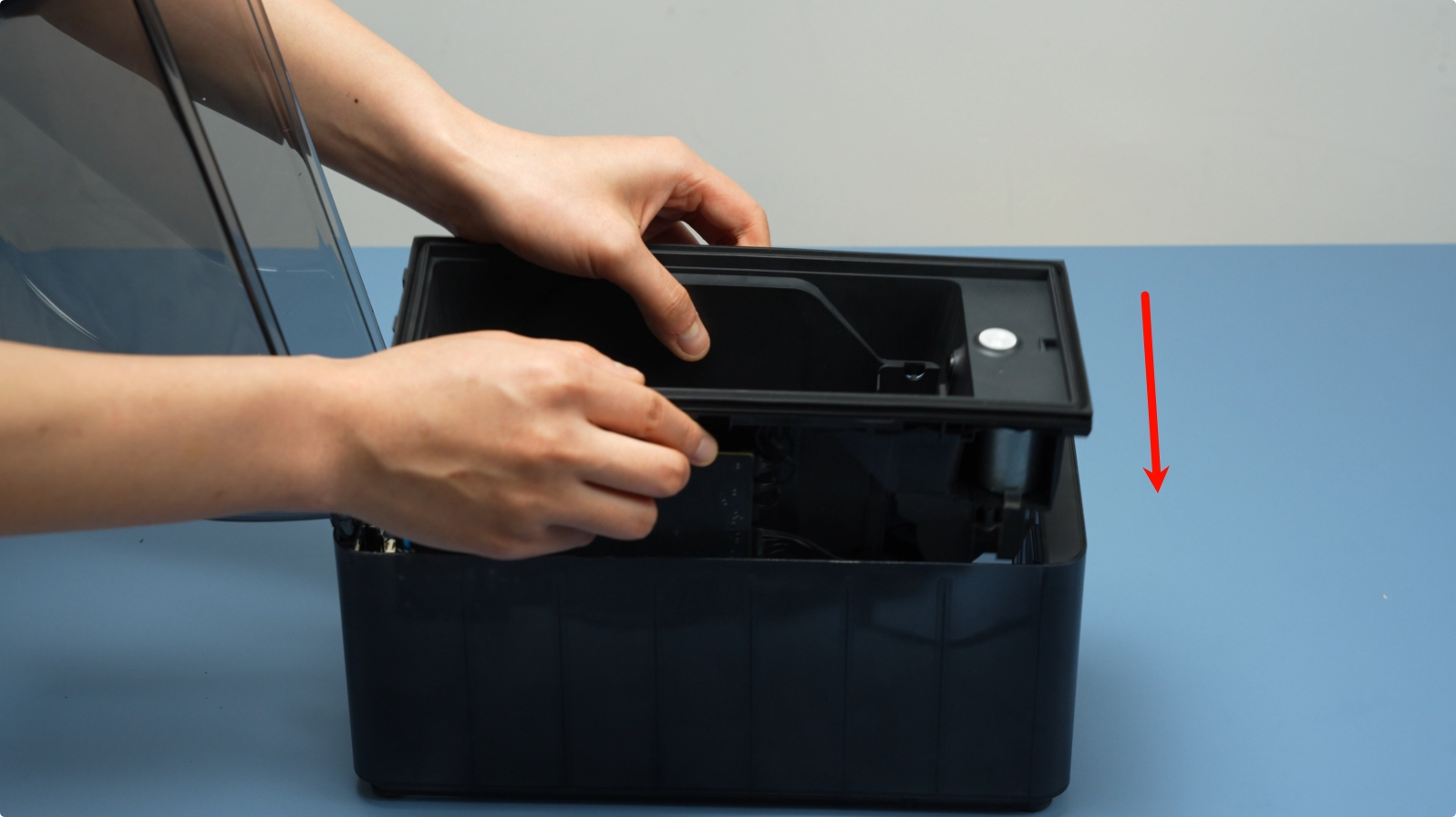
¶ Step 9: Mount the Frame
With the cables safely out of the way, carefully lower and install the main frame into the bottom cover.
¶ Step 10: Secure the Frame With the Screws
Insert and tighten the two bottom screws to firmly secure the frame in place.

¶ Step 11: Installing the PTFE Tube
Push the PTFE tube firmly into the rear connector of the AMS HT until it is fully seated.
If you have any concerns or questions about following this guide, open a new ticket in our Support Page and we will do our best to respond promptly and provide you with the assistance you need.
¶ Verify the functionality
Once you’re satisfied that everything is in order, proceed with the reconnection steps. You can check out the AMS HT part connection guide to learn how to properly connect it to your 3D printer. Next, turn on the printer, then enable the drying and feeding functions from the printer's interface. If the drying function starts and reaches its target temperature, the heating unit is functioning correctly.
You can then test the filament feeding process. If it runs without errors, the assembly was successful. If there are issues, you will need to disassemble again and inspect all internal cable connections and try again.
You can also run a self-test from the printer’s interface to verify motor functionality, cable communication, sensor feedback, and heating performance. If all systems pass without errors, your AMS HT is fully functional and ready for use.
¶ Potential problems and solutions
Here’s a list of potential problems that may arise during the assembly and disassembly of the AMS HT drying component, along with brief notes on each:
- Overtightened or Stripped Screws: Screws may be difficult to remove or may strip, especially if excessive force is used.
- Damaging the wires: Pulling and tugging the motherboard wires instead of the connector may snap them or disconnect them from PCB. Always grasp the connector and not wires.
- Cable connector damage: Pulling cables without releasing clips can damage connectors or ports on the motherboard.
- Loose or misrouted cables: Poor cable routing can obstruct motherboard operation or cause damage.
¶ End Notes
We hope our guide was helpful. If you have any questions or concerns about the process, please contact our customer service team. We're here to assist you.
Click here to open a new ticket in our Support Page.
We will do our best to respond promptly and provide you with the assistance you need.