¶ 2004 Lifting Motor Unit
The 2004 lifting motor unit consists of a lifting motor and a lifting motor gearbox. It is used to control the elevation of the left hotend.
 |
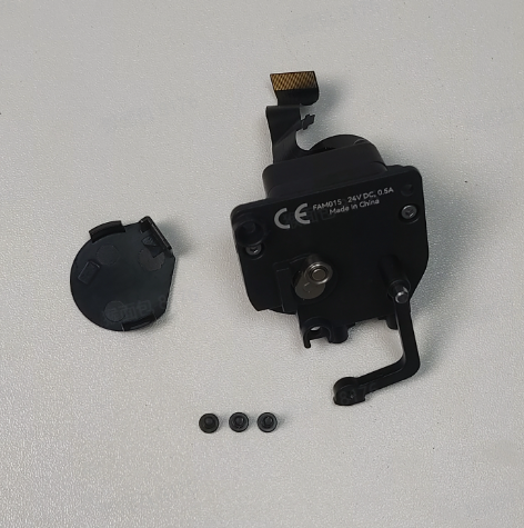 |
The spare parts for the 2004 lifting motor unit include:
-
2004 lifting motor unit (pre-assembled with the lifting motor and gearbox) × 1
-
Lifting motor cover (replace only if damaged) × 1
-
Rocker arm × 1
-
Graphite washer × 1
-
M2.5×5 screws (used to fix the lifting motor gearbox) × 3
-
BT2×5 screws (used to fix the lifting motor) × 2
¶ When to use
-
Abnormal operation of the lifting motor
-
Abnormal operation of the lifting motor gearbox
¶ Tools and materials needed
-
New part cooling fan
-
H2.0 Allen key
-
H1.5 Allen key
Specifications and quantities of screws involved in replacing the H2D lifting motor unit (it is recommended to keep the removed screws properly to avoid loss):
| Specification | Use | Position | Quantity |
|---|---|---|---|
| BT3x8 | Fix the part cooling fan air duct | 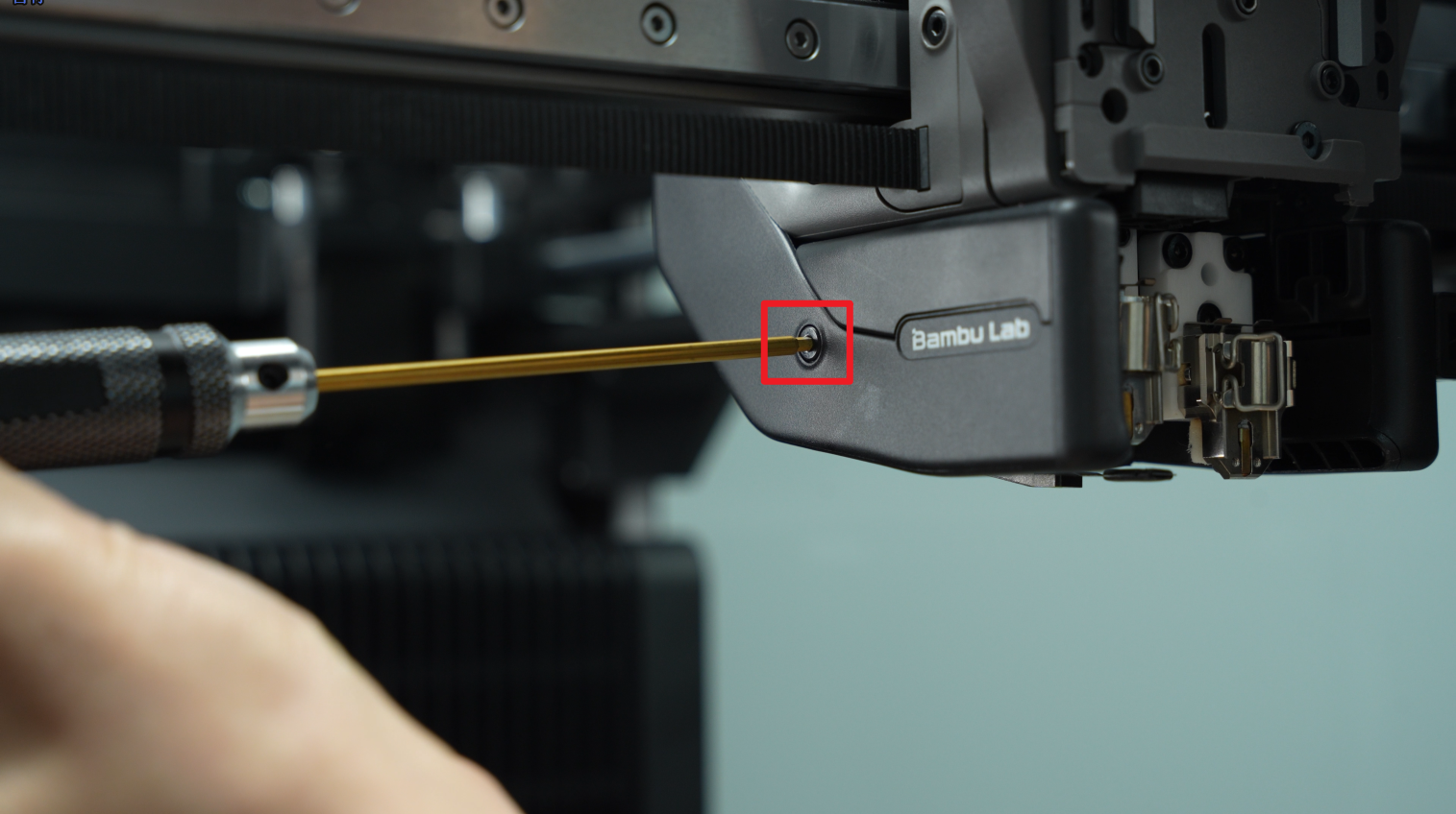 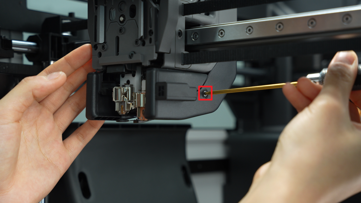 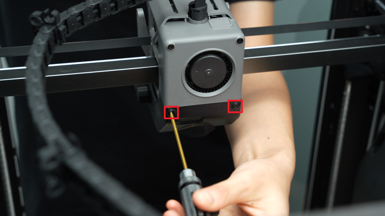 |
4 |
| BT3x20 | Fix the part cooling fan | 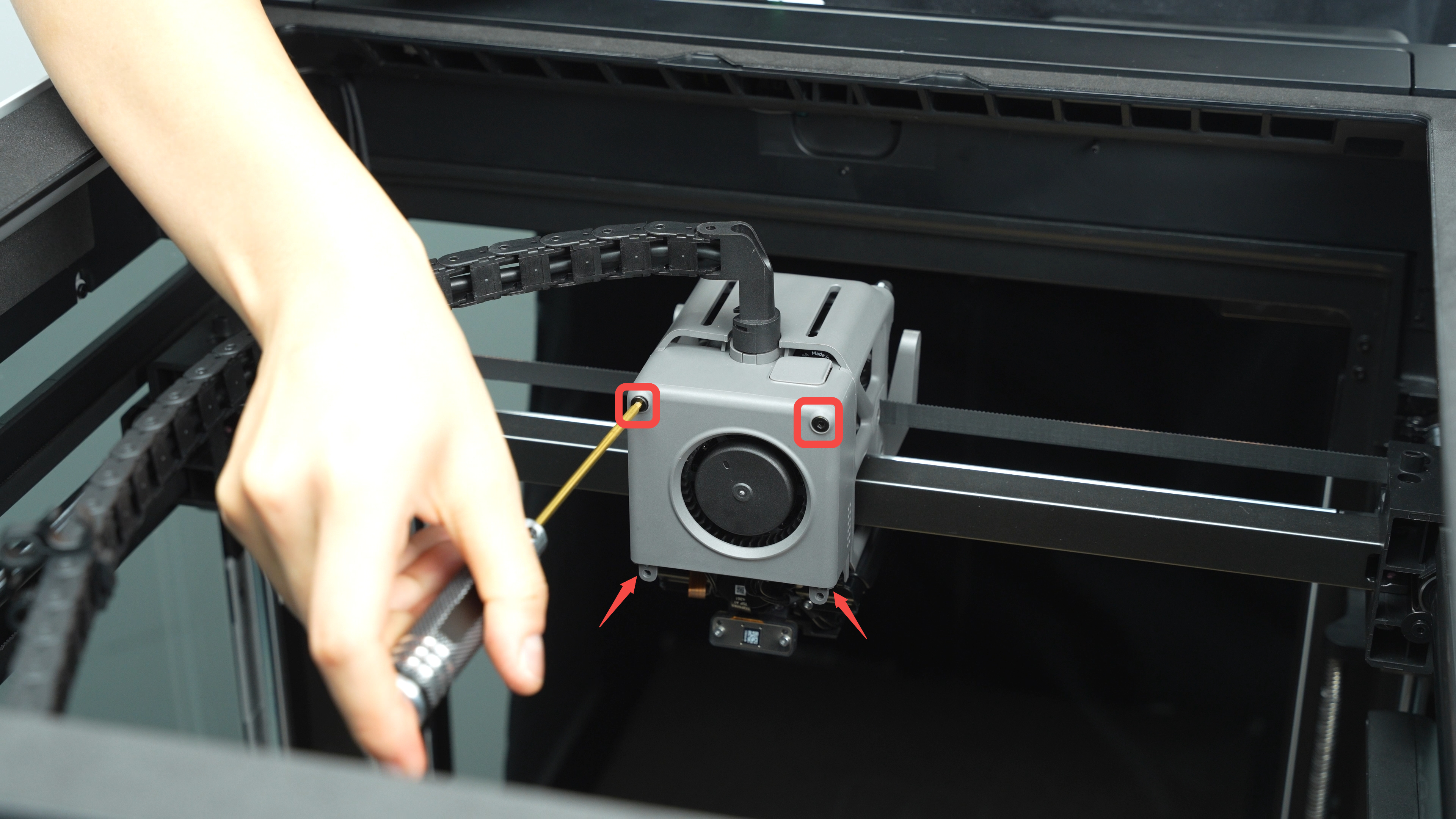 |
2 |
| BT2.6x8 | Fix the part cooling fan | 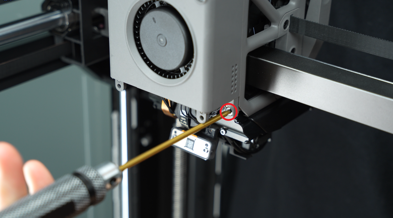 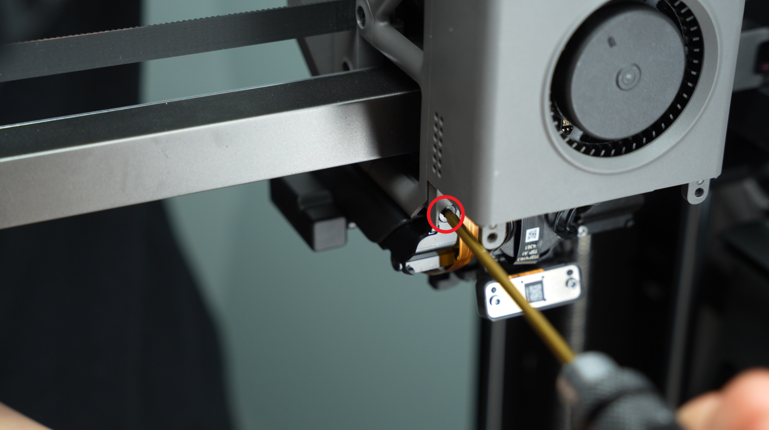 |
2 |
| Fix the TH board | 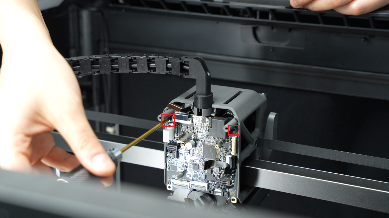 |
2 | |
| M1.6x4 | Fix the extruder connection board | 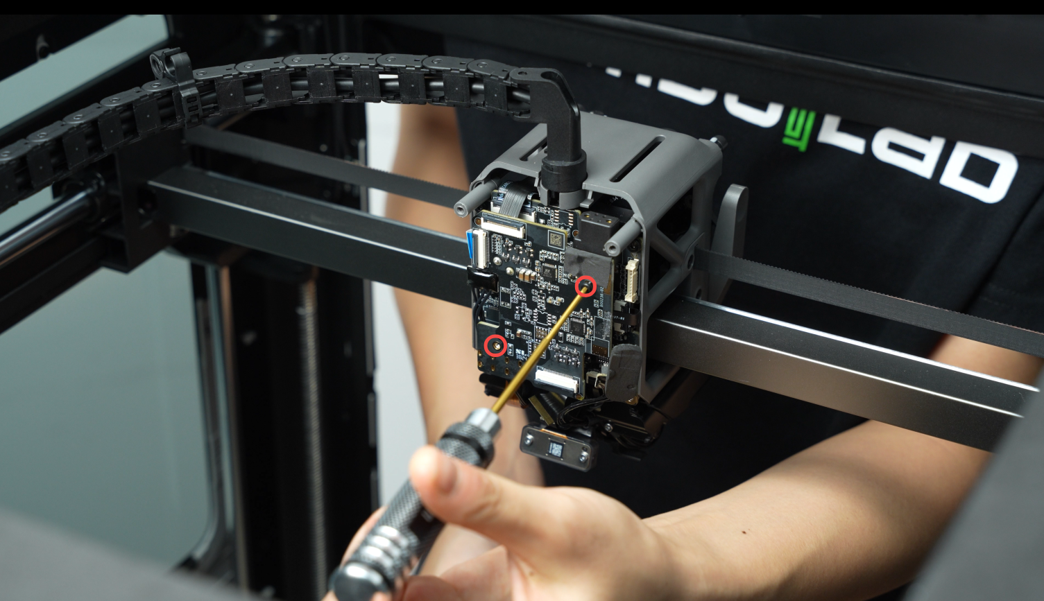 |
2 |
| M2.5x8 | Fix the cooling fan for hotend | 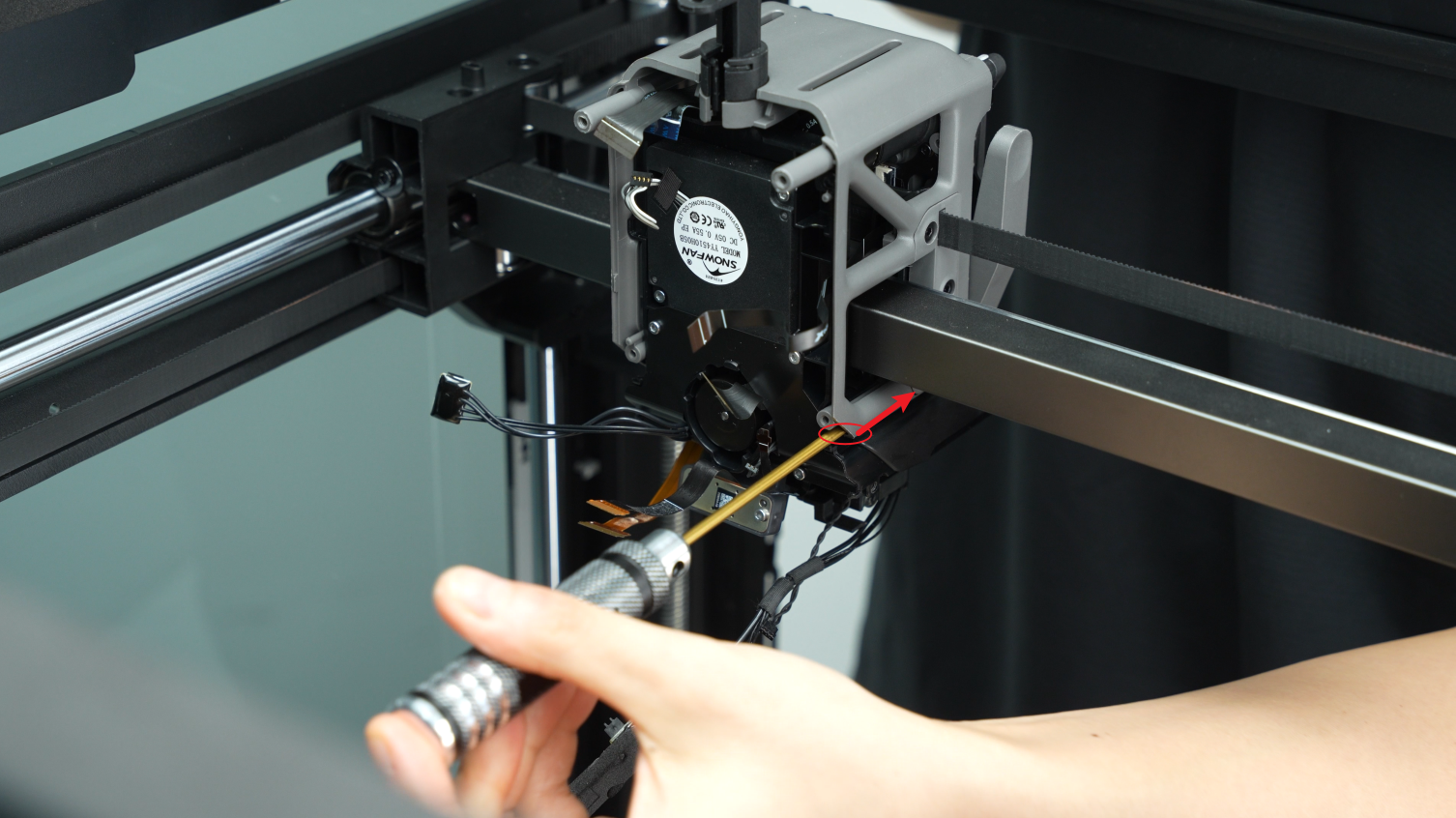 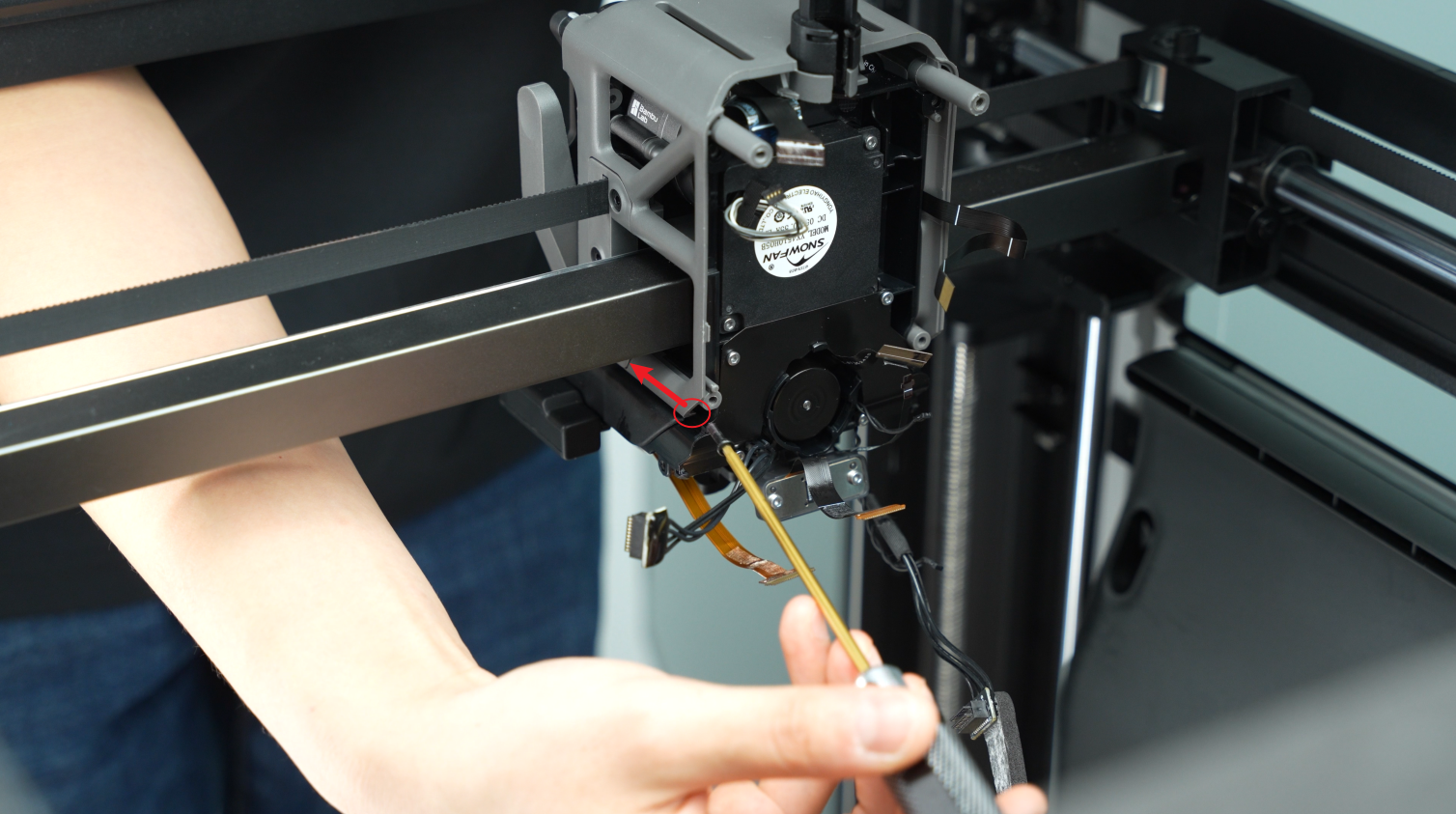 |
2 |
| BT2x5 | Fix the nozzle camera | 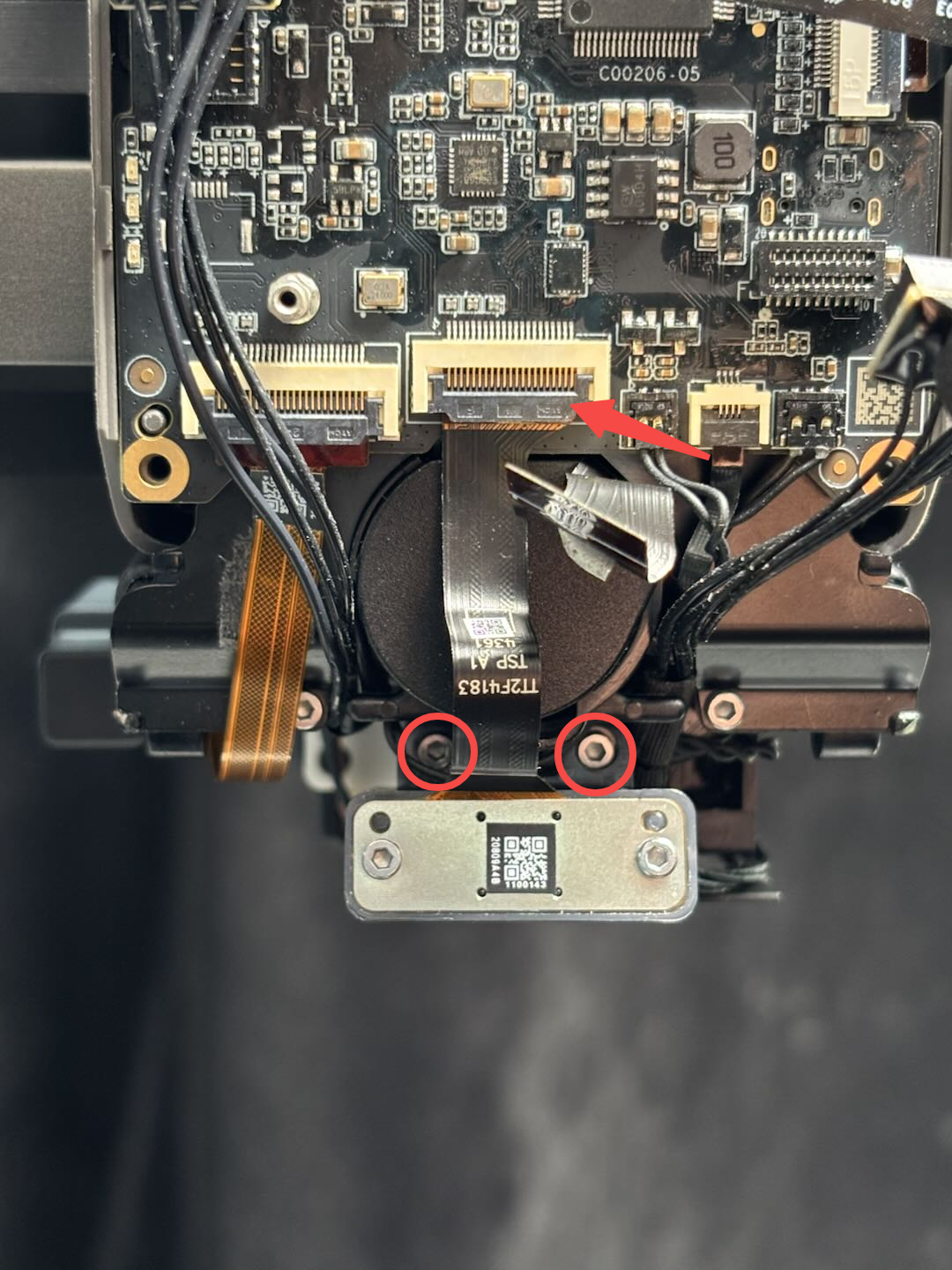 |
2 |
| M2.5x5 | Fix the lifting motor gearbox | 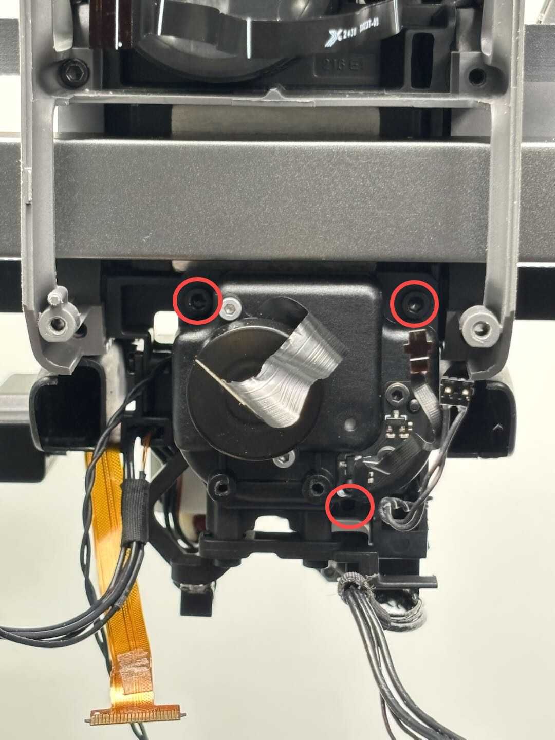 |
3 |
| M2.5x2 | Fix the nozzle blocker magnet bracket | 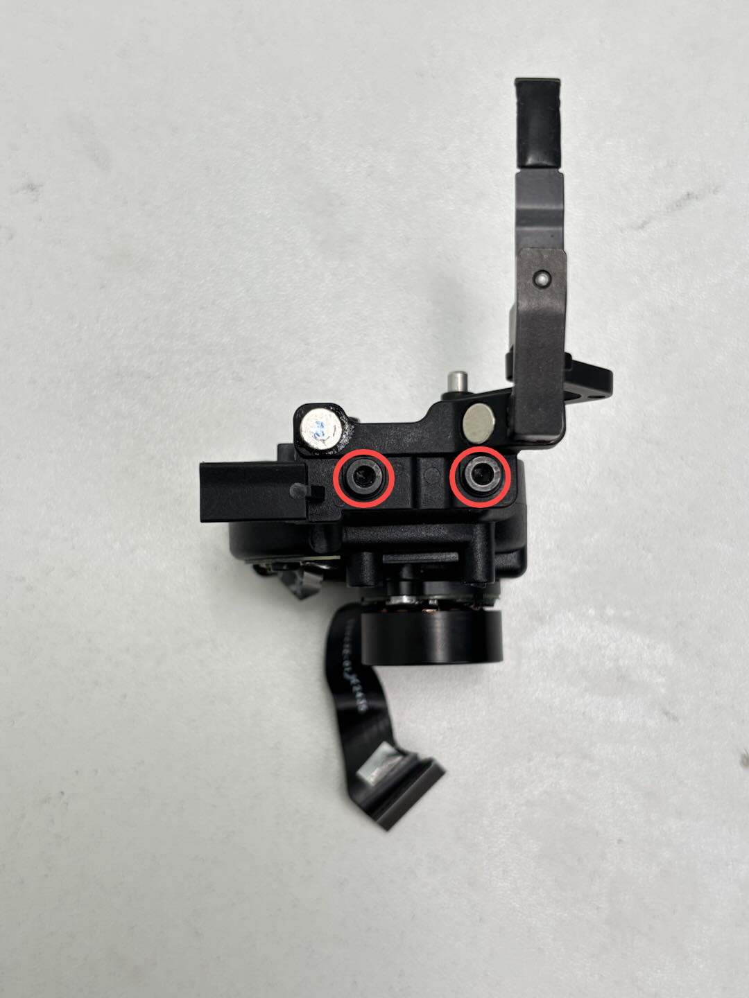 |
2 |
| M2.5x8x3 | Fix the nozzle blocket | 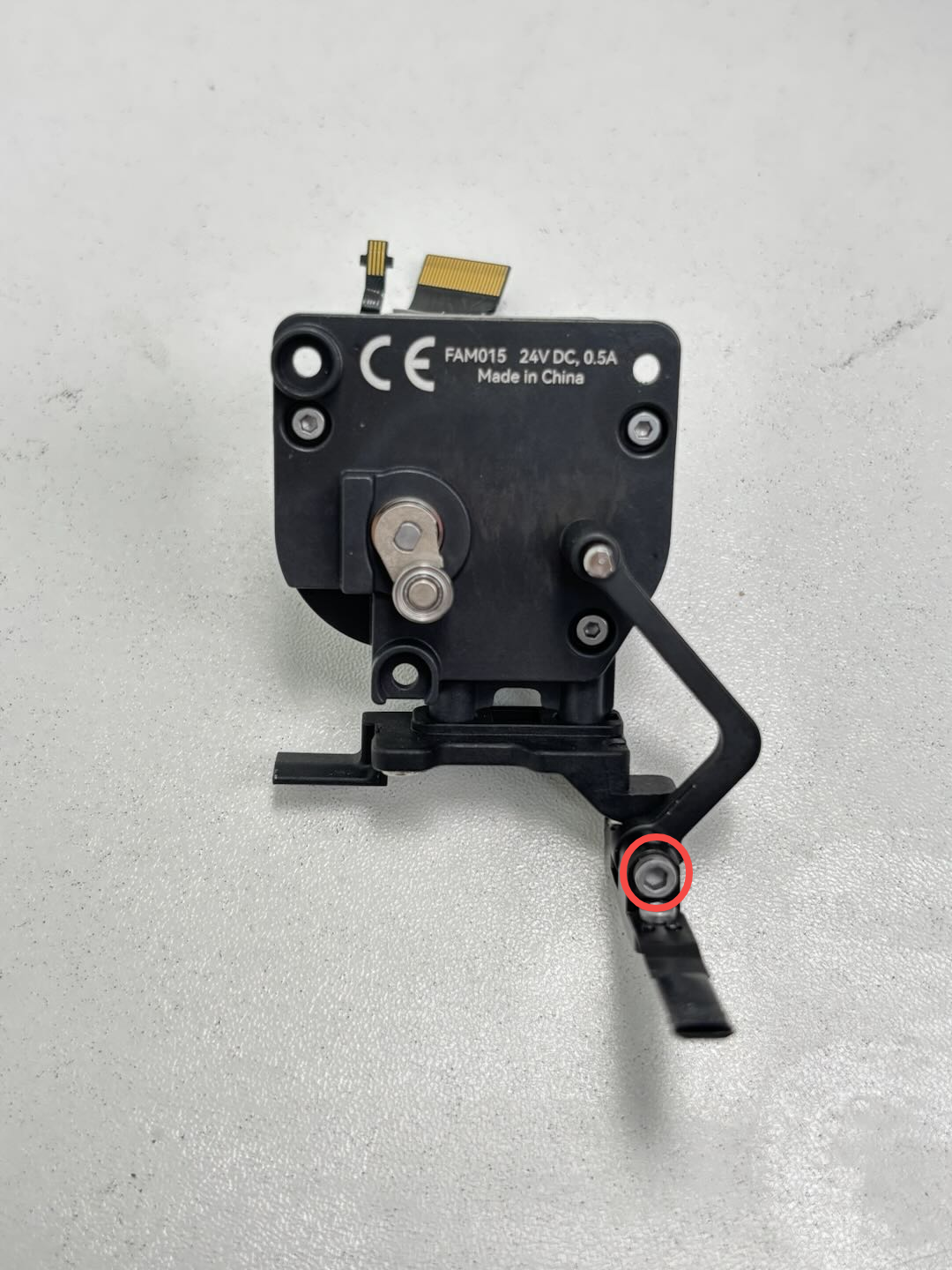 |
1 |
¶ Safety Warning
IMPORTANT!
It's crucial to power off the printer before conducting any maintenance work, including work on the printer's electronics and tool head wires. Performing tasks with the printer on can result in a short circuit, leading to electronic damage and safety hazards.
During maintenance or troubleshooting, you may need to disassemble parts, including the hotend. This exposes wires and electrical components that could short circuit if they contact each other, other metal, or electronic components while the printer is still on. This can result in damage to the printer's electronics and additional issues.
Therefore, it's crucial to turn off the printer and disconnect it from the power source before conducting any maintenance. This prevents short circuits or damage to the printer's electronics, ensuring safe and effective maintenance. For any concerns or questions about following this guide, we recommend submitting a technical ticket regarding your issue and we will do our best to respond promptly and provide the assistance you need.
¶ Remove the 2004 Lifting Motor Unit
¶ Step 1: Remove the cooling fan for hotend and bracket
To remove the 2004 lifting motor unit, the cooling fan for hotend must be removed first. Therefore, you can refer to this Wiki for instructions on removing the cooling fan for hotend and its bracket:
Replace H2D Cooling Fan for Hotend and Bracket
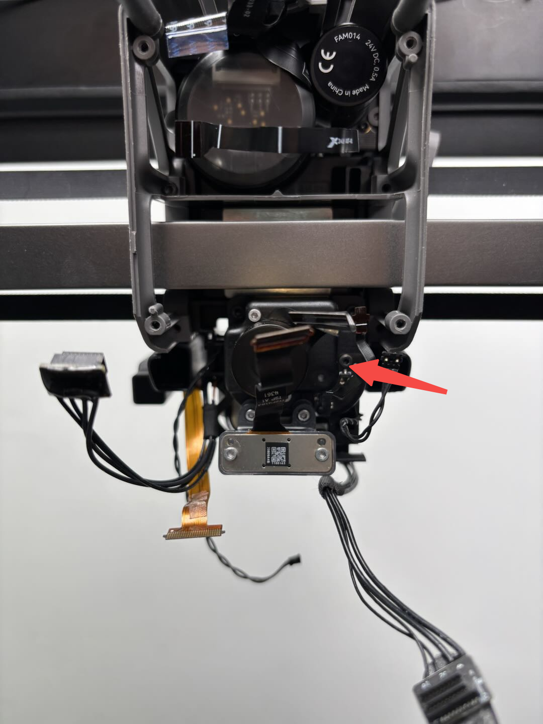
¶ Step 2: Remove the nozzle camera
Since one screw of the 2004 lifting motor unit is blocked by the nozzle camera, you can use an H1.5 Allen key to remove the 2 fixing screws of the nozzle camera and then take it off.
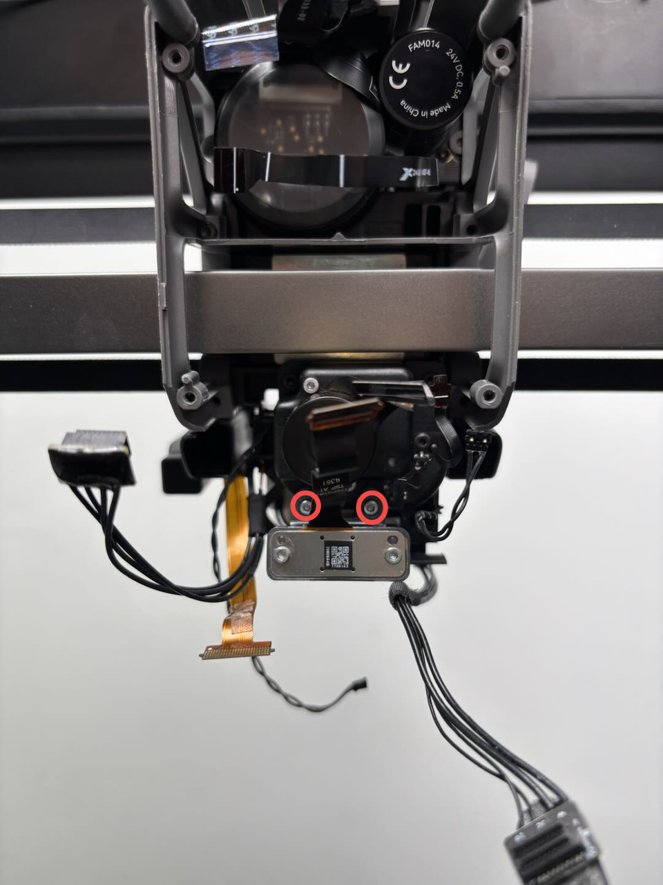
¶ Step 3: Remove the 2004 Lifting Motor Unit
Use an H2.0 Allen key to remove the 3 fixing screws of the lifting motor gearbox. Then, carefully detach the lifting motor unit from the toolhead. When removing the last screw, support the lifting motor unit with your hand to prevent it from falling.

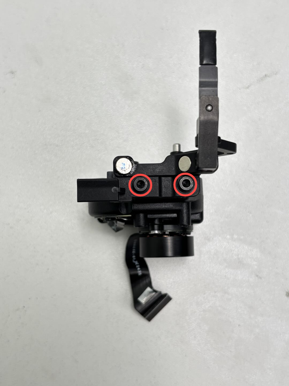
¶ Step 4: Remove the nozzle blocker magnet bracket and nozzle blocker
Since the nozzle blocker magnet bracket and nozzle blocker are installed on the lifting motor unit (and are not included with the lifting motor unit itself), you need to remove them from the old unit and install them onto the new one. You can use an H2.0 Allen key to remove one fixing screw of the nozzle blocker and detach it, and use an H2.0 Allen key to remove 2 fixing screws of the nozzle blocker magnet bracket and detach it.
 |
 |
¶ Install the 2004 Lifting Motor Unit
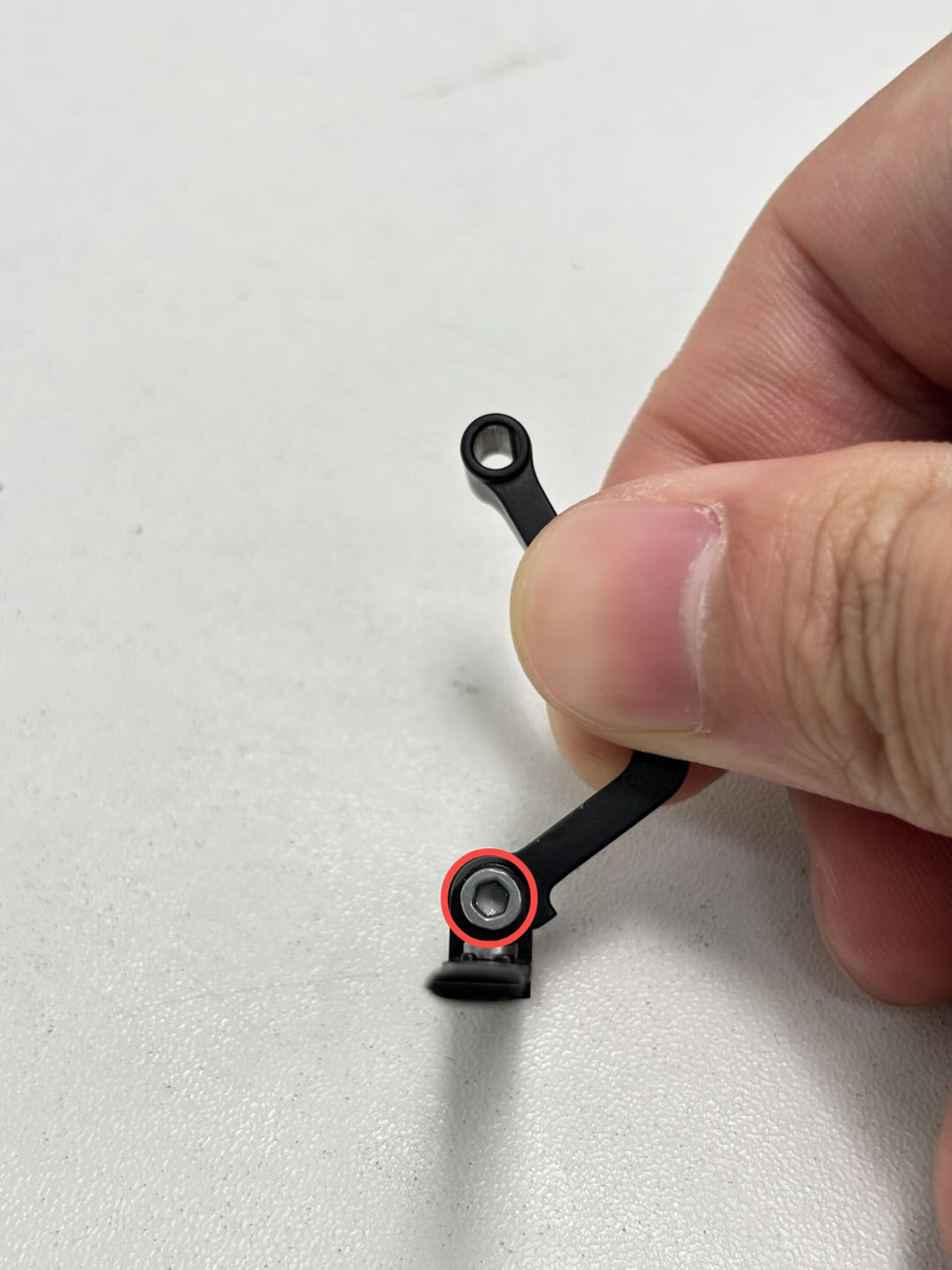
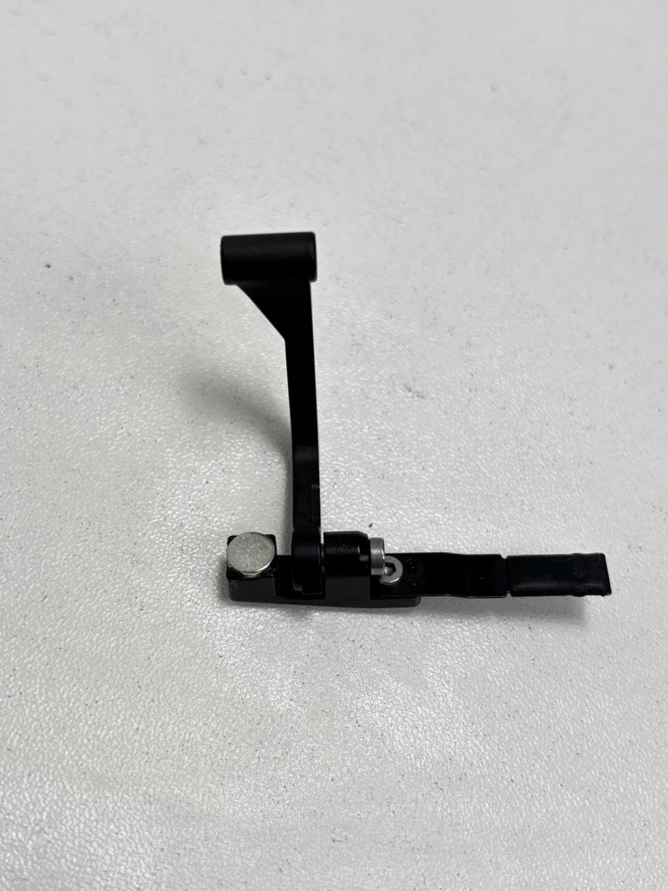
¶ Step 1: Install the nozzle blocker magnet bracket and nozzle blocker
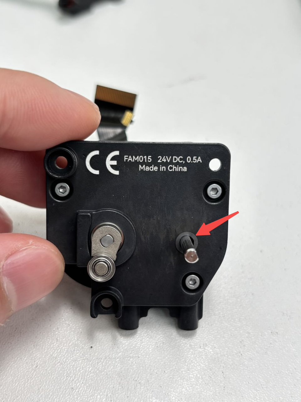
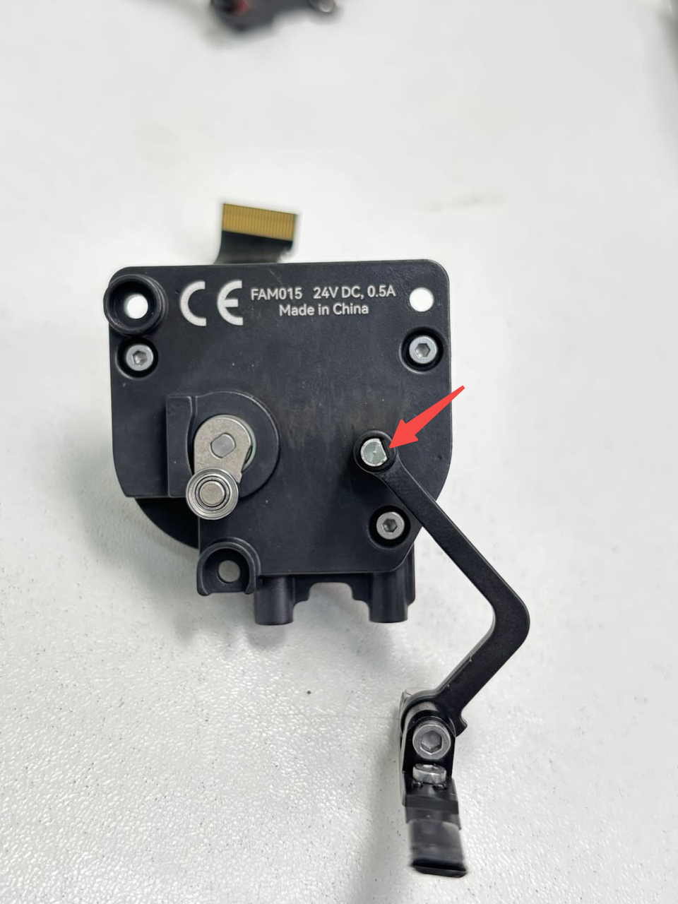
Connect the existing nozzle blocker to the rocker arm (refer to the image for installation), and use an H2.0 Allen key to tighten one fixing screw.
 |
 |
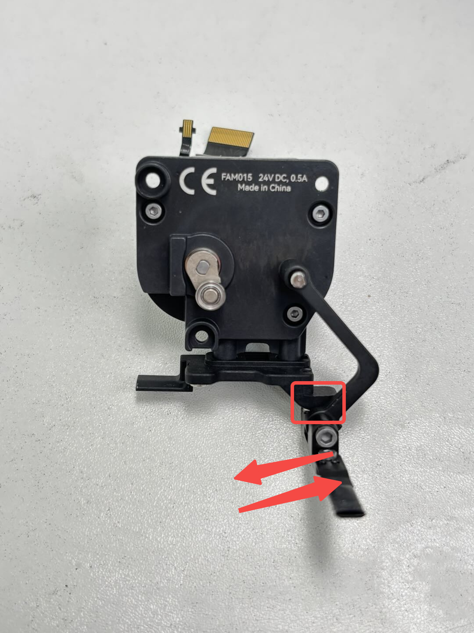
Insert the graphite washer onto the bearing of the lifting motor, then align the flat surface of the rocker arm with the flat surface of the bearing and install the rocker arm onto the lifting motor unit. Finally, align the screw holes of the nozzle blocker magnet bracket with the lifting motor unit and use an H2.0 Allen key to tighten 2 fixing screws.
 |
 |
 |
¶ Step 2: Install the 2004 lifting motor unit
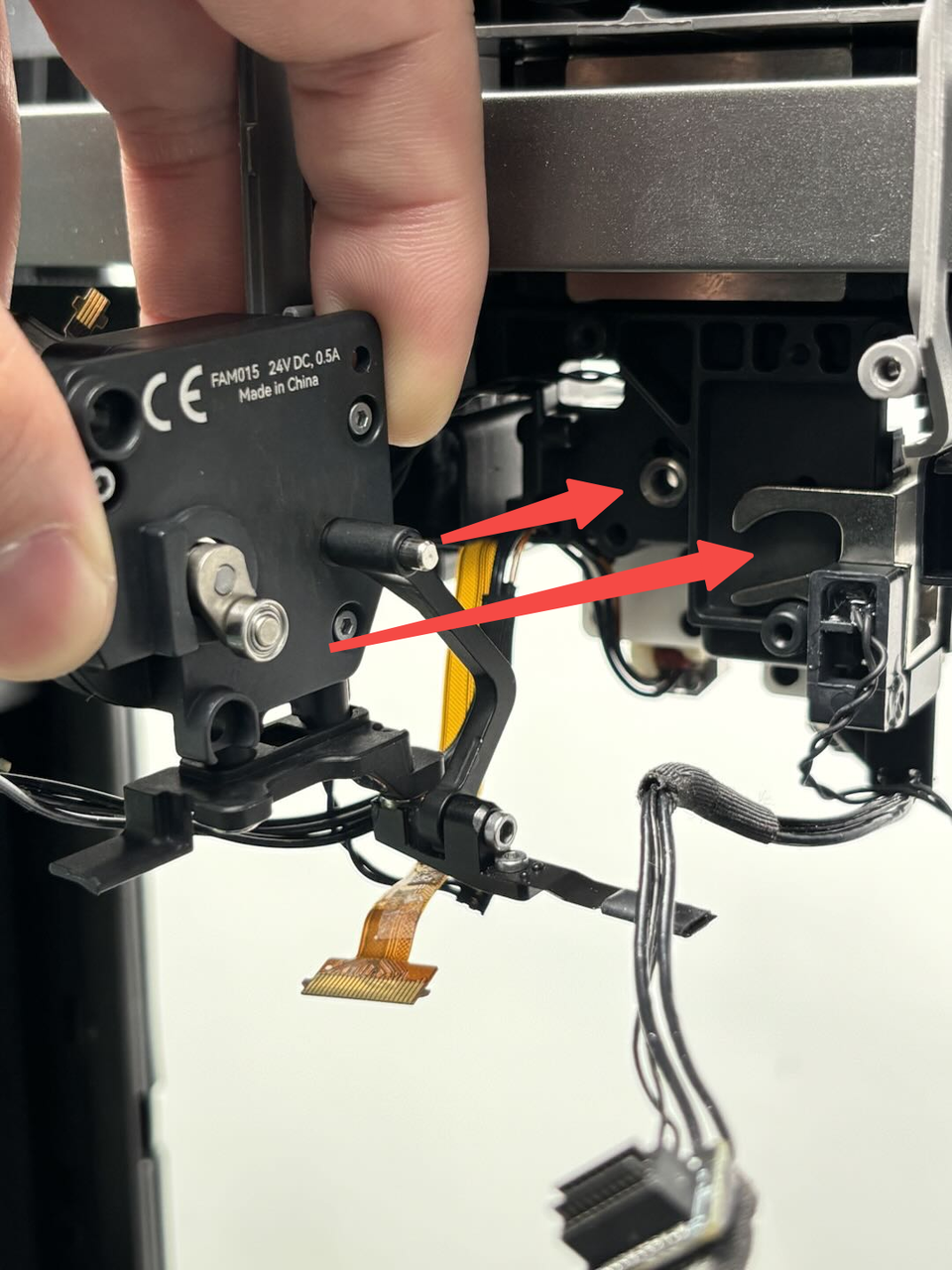
Align the two bearings of the lifting motor unit with the corresponding holes on the toolhead. Please note that the bearing on the left side is secured in the lifting slider. When the lifting slider is at the bottom, the left bearing should also be at the bottom (as shown in the image). If it is not in the correct position, the lifting motor unit cannot be installed. You can adjust the position by moving the rocker arm.
As shown in the example image, first, swing the rocker arm to attach the nozzle blocker to the magnet on the right side of the nozzle blocker magnet bracket (indicated by the box). This ensures the lifting slider is at the bottom. Align the two bearings of the lifting motor unit with the corresponding holes on the toolhead and install it, and use an H2.0 Allen key to tighten 3 fixing screws.
 |
 |
 |
¶ Step 3: Install the nozzle camera
Align the nozzle camera with the screw holes on the lifting motor unit and use an H1.5 Allen key to tighten 2 fixing screws.

¶ Step 4: Install the cooling fan for hotend and bracket
You can refer to this Wiki for instructions on installing the cooling fan for hotend and its bracket:
Replace H2D Cooling Fan for Hotend and Bracket
¶ Verify the Functionality
Connect the power and turn on the printer. Switch the hotend on the screen and check if it functions properly.
¶ End Notes
We hope the detailed guide provided has been helpful and informative.
If this guide does not solve your problem, please submit a technical ticket, we will answer your questions and provide assistance.
If you have any suggestions or feedback on this Wiki, please leave a message in the comment area. Thank you for your support and attention!