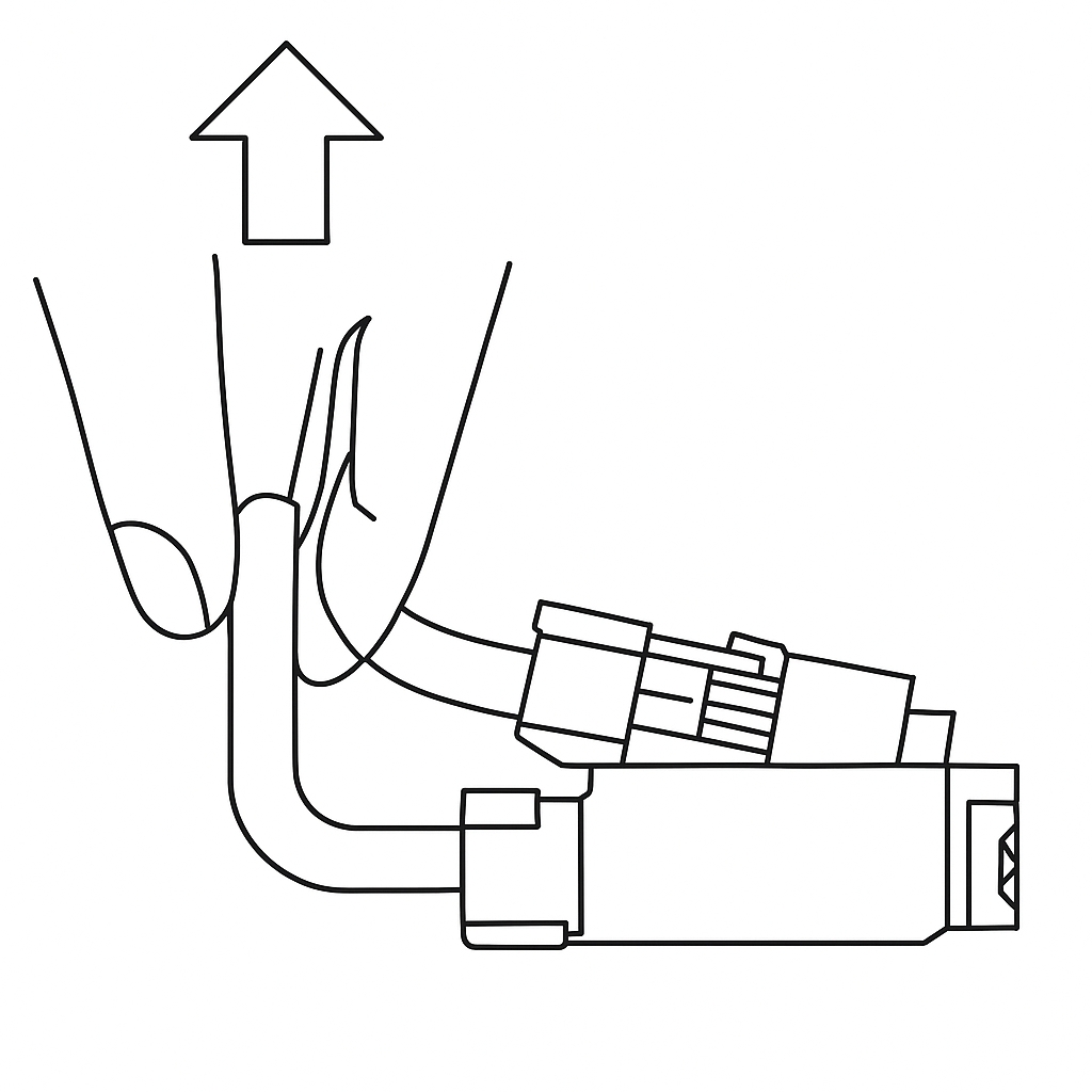
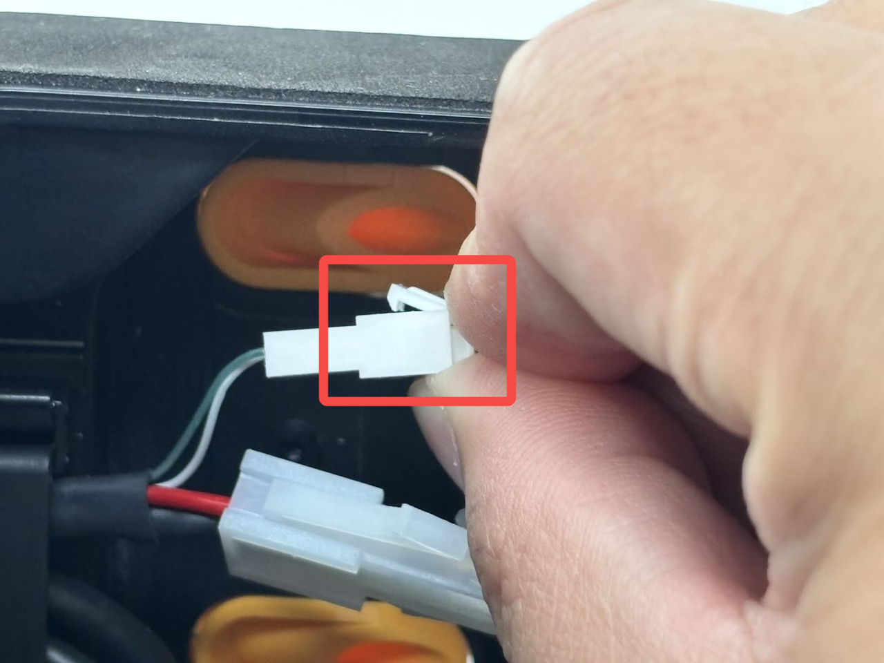
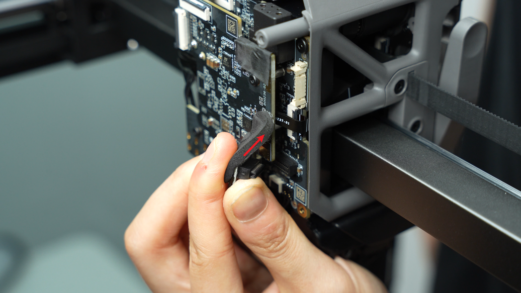
¶ Important Reminder
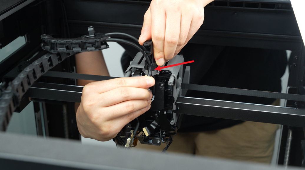
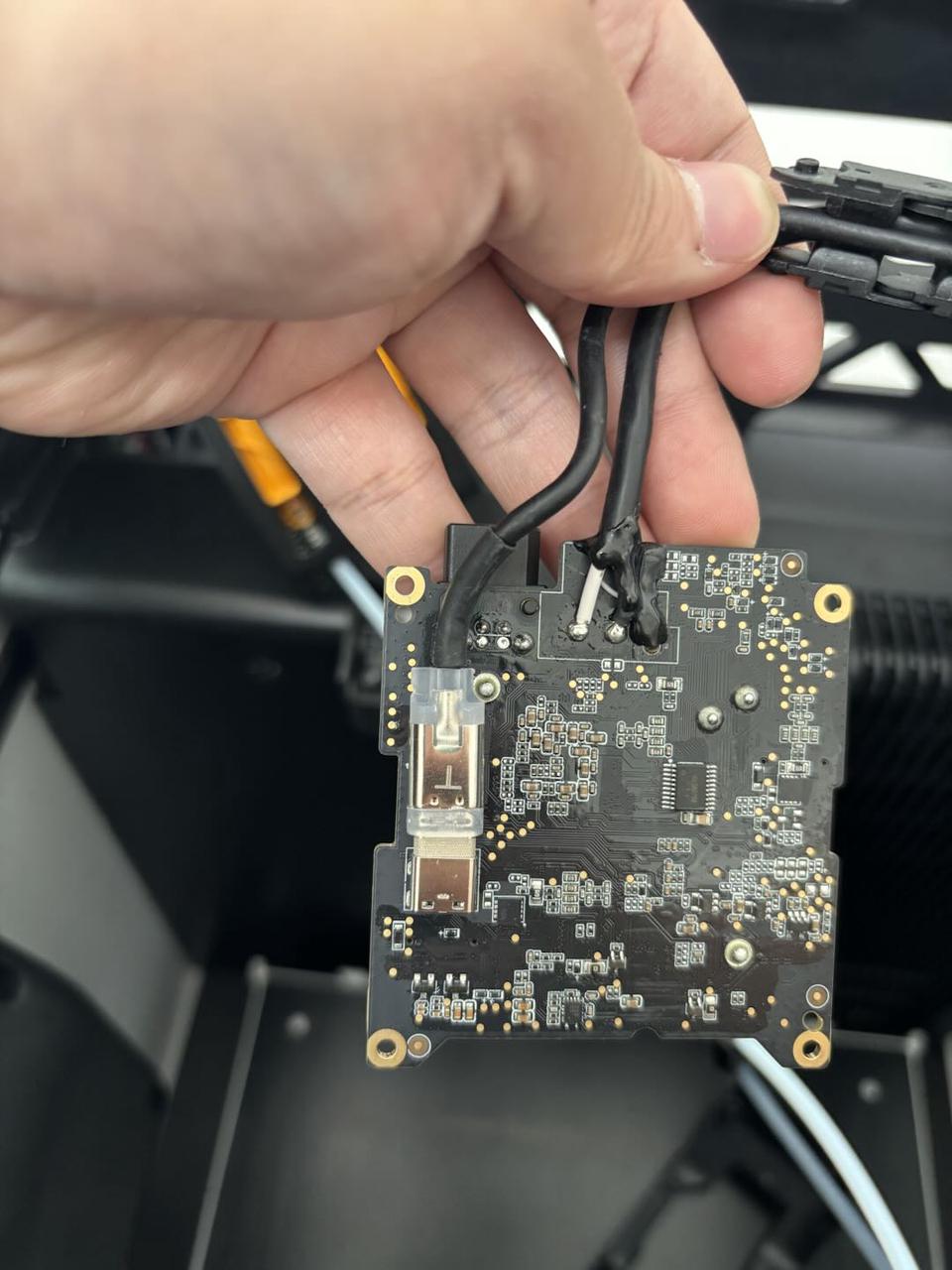
The fan and eddy sensor coil connectors on the H2D feature this compact connector design. When removing the connector, please hold the base of the connector with your hand and lift straight up, perpendicular to the PCB surface, to unlock it. Never apply force in the horizontal direction to avoid damaging the connector.
¶ Extruder Connection Board/TH Board/FPC Cable
This guide includes the replacement tutorials of the extrusion connection board/TH board/FPC cable. You can replace the corresponding spare parts according to your actual needs.;
For example: If you only need to replace the FPC cable, you can skip the subsequent steps of replacing the TH board.
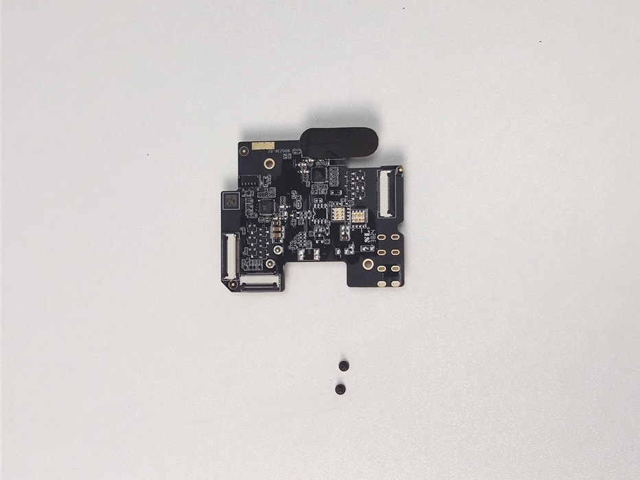
The TH board and the extrusion connection board are installed on the back of the toolhead, and they are connected by the FPC cable. The details of the TH board, extrusion interface board and accessories are as follows:
The spare parts for the extruder connection board are as follows:
-
Extruder connection board * 1
-
M1.6x4 screw - used to fix the extruder connection board * 2
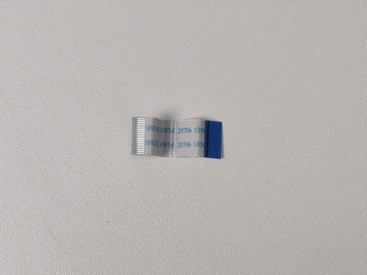
The spare parts for the FPC cable are as follows:
- FPC cable * 1
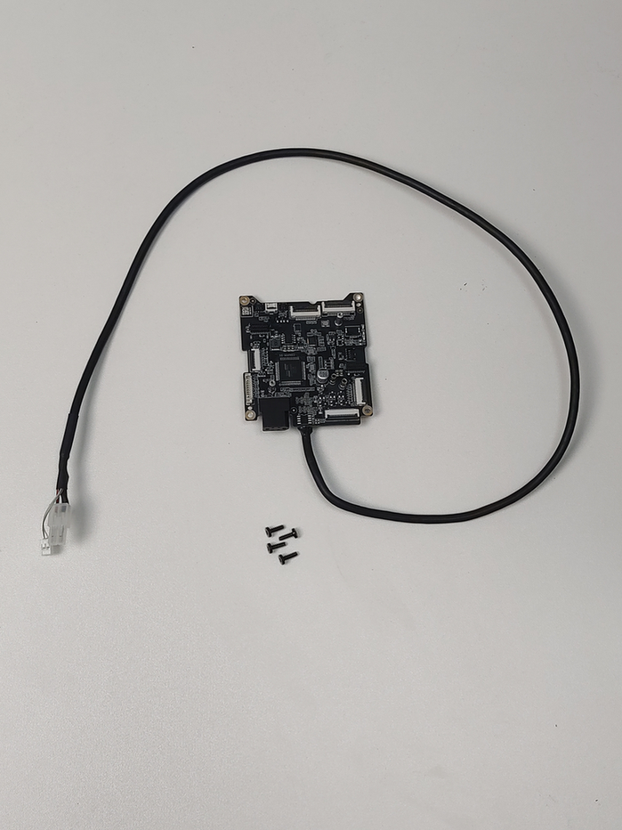
The spare parts for the TH board are as follows:
-
TH board * 1
-
BT2.6x8 screws - used to fix the TH board * 4
¶ Tools and Materials Needed
-
New TH Board/FPC Cable/Extruder Connection Board (Select the corresponding part based on your specific needs for replacement)
-
H2.0 Allen Key
-
H1.5 Allen Key
Specifications and quantities of screws involved in replacing the H2D extruder connection board/TH board/FPC cable (it is recommended to keep the removed screws properly to avoid loss):


¶ Safety Warning
IMPORTANT!
It's crucial to power off the printer before conducting any maintenance work, including work on the printer's electronics and tool head wires. Performing tasks with the printer on can result in a short circuit, leading to electronic damage and safety hazards.
During maintenance or troubleshooting, you may need to disassemble parts, including the hotend. This exposes wires and electrical components that could short circuit if they contact each other, other metal, or electronic components while the printer is still on. This can result in damage to the printer's electronics and additional issues.
Therefore, it's crucial to turn off the printer and disconnect it from the power source before conducting any maintenance. This prevents short circuits or damage to the printer's electronics, ensuring safe and effective maintenance. For any concerns or questions about following this guide, we recommend submitting a technical ticket regarding your issue and we will do our best to respond promptly and provide the assistance you need.
¶ Remove the Extruder Connection Board/TH Board/FPC Cable
¶ Step 1: Remove the part cooling fan air duct and the fan
You can refer to this Wiki for instructions on removing the part cooling fan air duct and part cooling fan: How to replace the H2D part cooling fan. Or you can watch the first 1:40 of the video below to see how to do it.
¶ Step 2: Remove the Extruder connection board
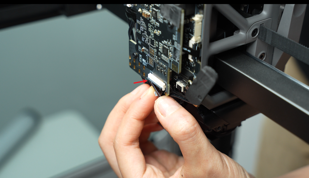
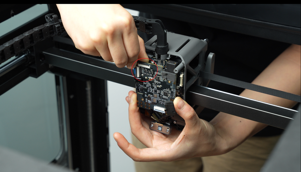
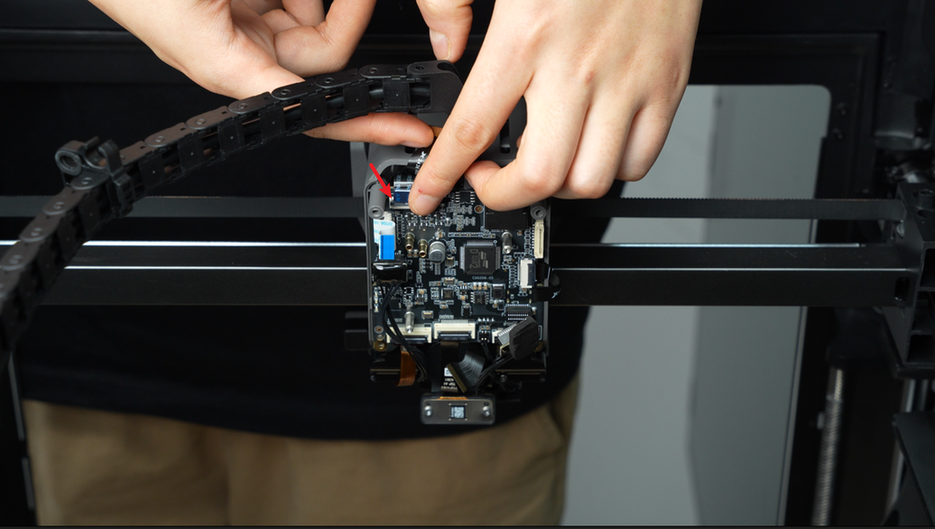
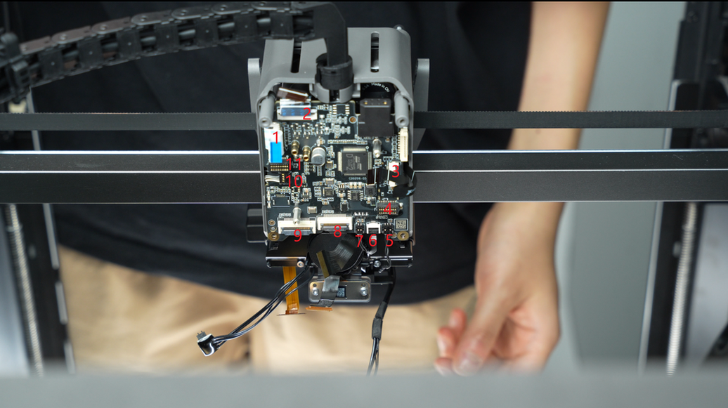
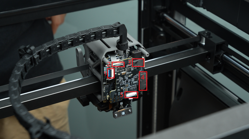
Disconnect the following connectors on the interface board in sequence: 2004 switching motor FPC connector, TH board FPC connector, left hotend heating assembly connector and its foam (the connector is on the TH board, and the foam is on the extruder connection board), and 2004 lifting motor FPC connector.
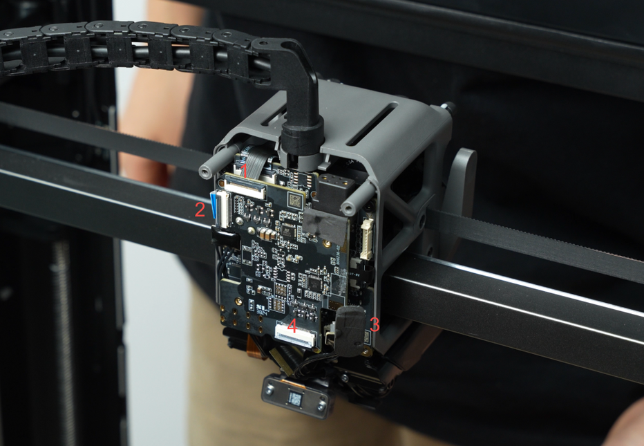
| No. | Connected to | No. | Connected to |
|---|---|---|---|
| 1 | 2004 switching motor | 2 | TH board |
| 3 | Left hotend heating assembly | 4 | 2004 lifting motor |
Note:
- The 2004 switching motor cable (No. 1), FPC cable (No. 2) and 2004 lifting motor cable (No. 4) are secured by latches. Unlock the latches before pulling out the FPC cables.
No. 1
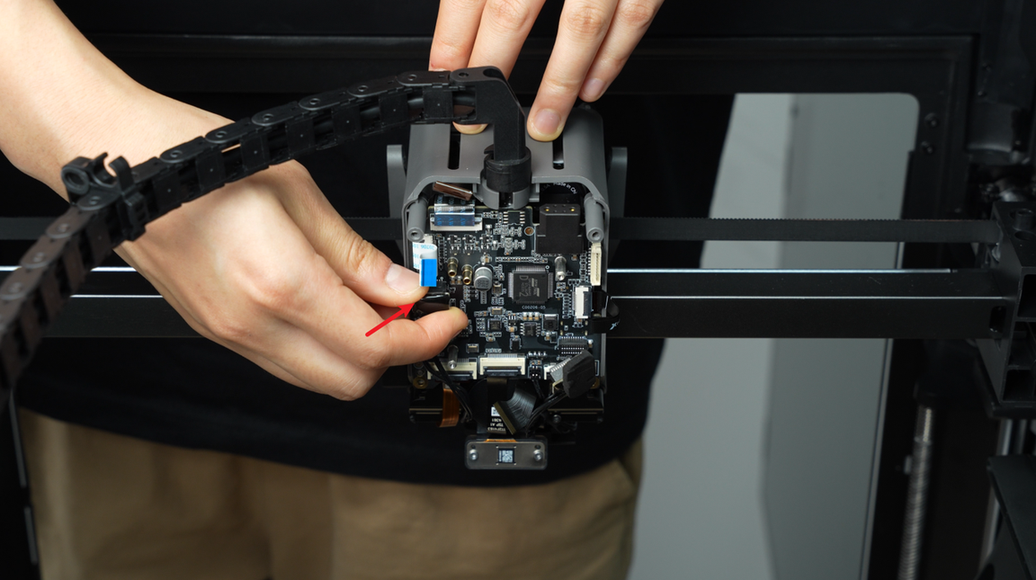
No. 2
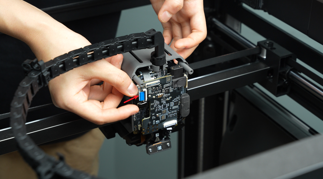
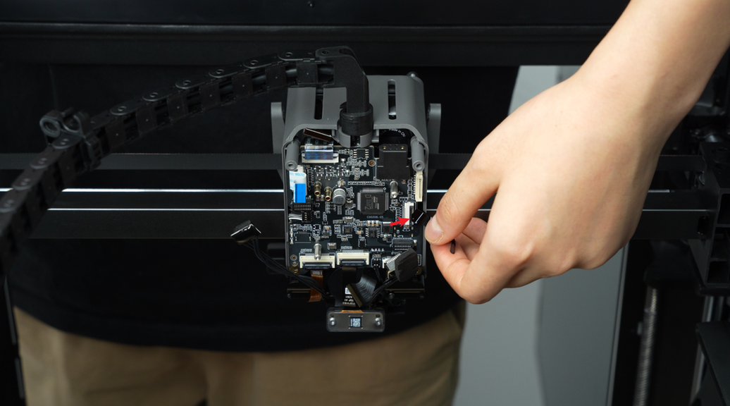
No. 4
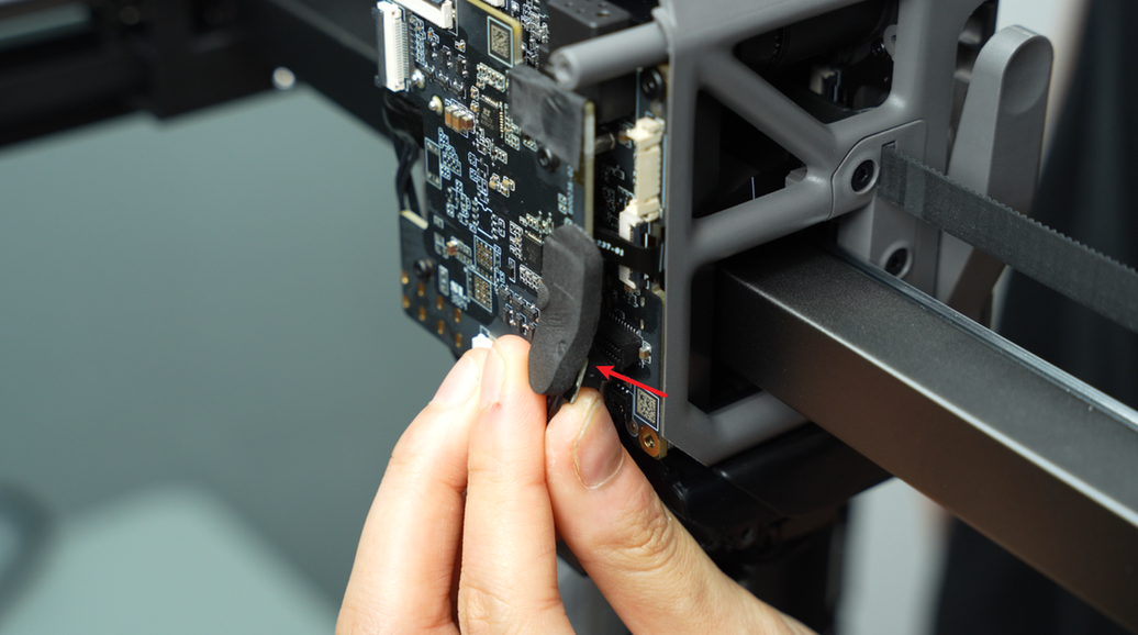
- When peeling off the foam on the left hotend heating assembly connector (No. 3), it is recommended to loosen the connector first, then peel from bottom to top to maintain the foam’s integrity.

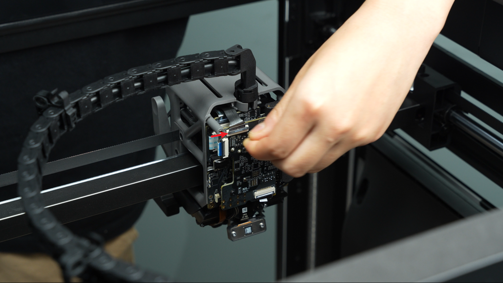
Use an H1.5 Allen key to remove the 2 fixing screws (M1.6x4).
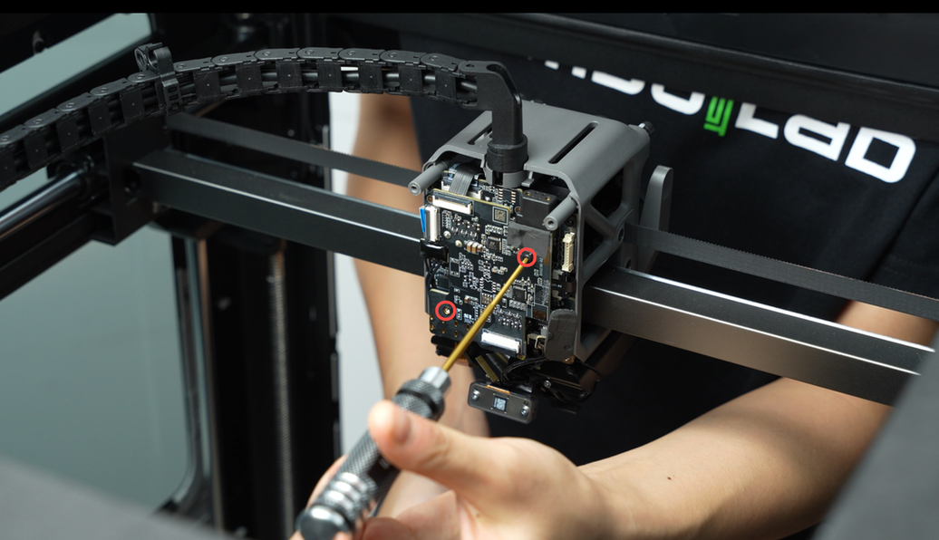
Gently wiggle the extruder connection board near the 2004 switching motor connector and carefully remove it.
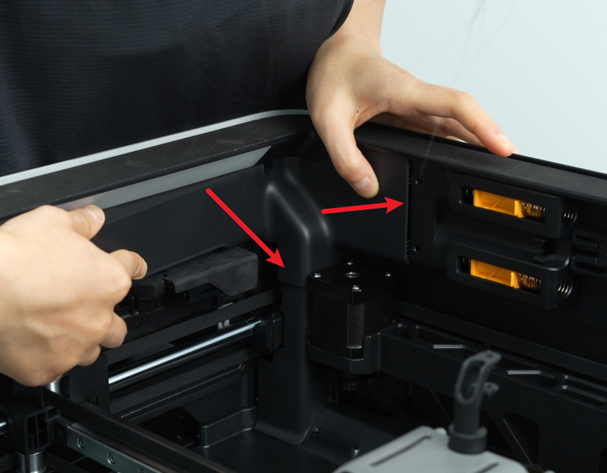
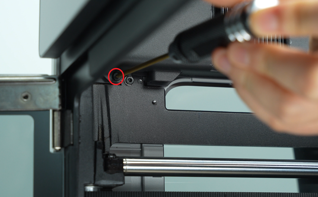
¶ Step 3: Remove the filament buffer and AP board cover
- Remove the AP board cover
Since the MC-TH cable is covered behind the filament buffer and AP board cover, they need to be removed first.
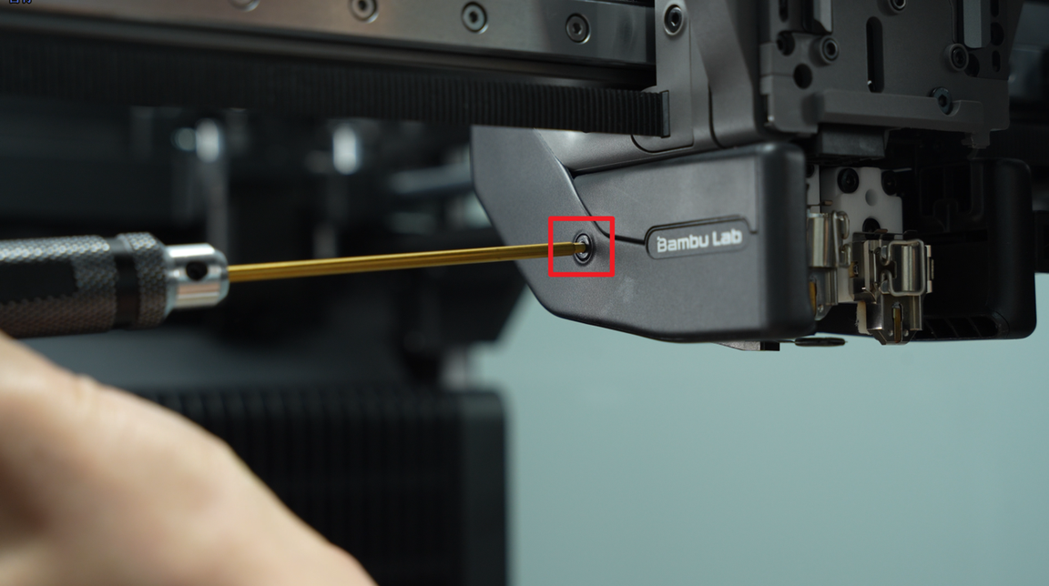
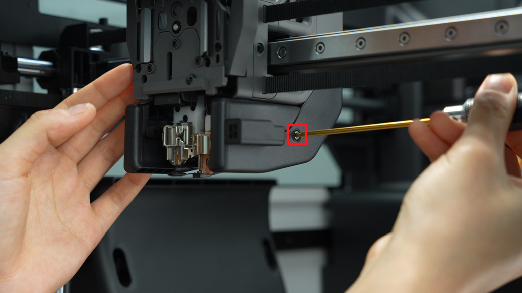
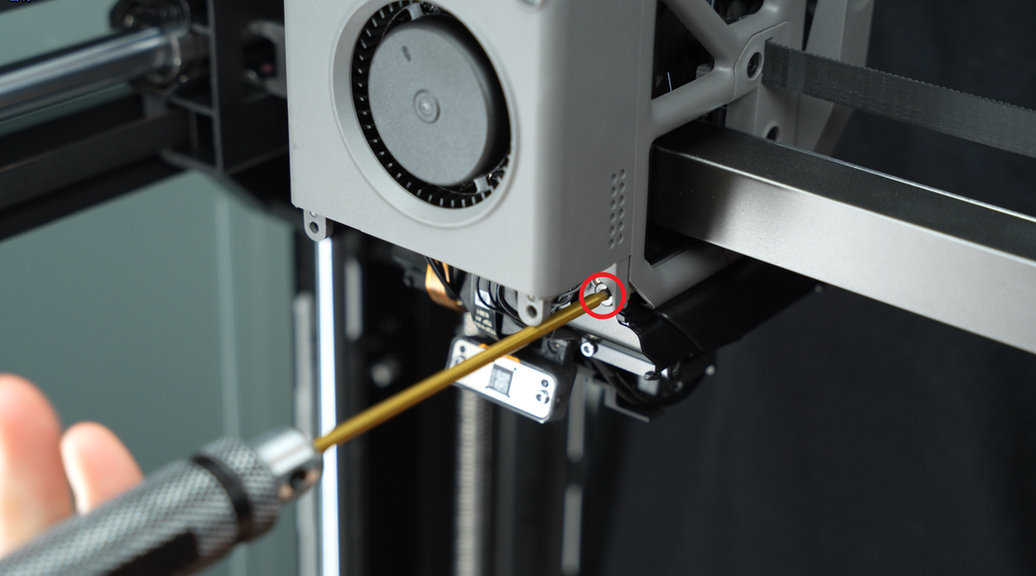
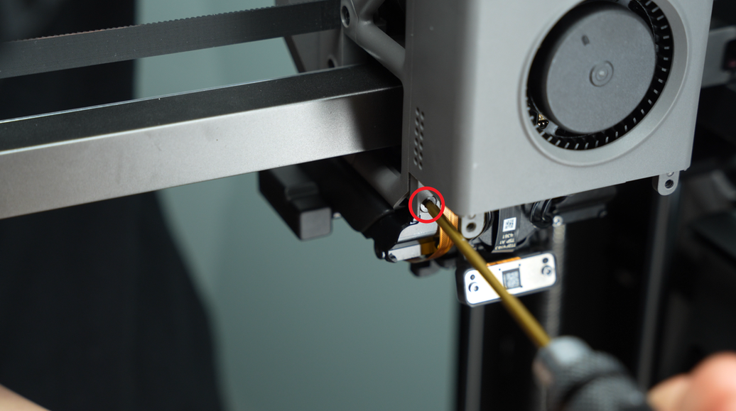
Use an H2.0 Allen key to unscrew one fixing screw (BT2.6x8).

Then remove the AP board cover from the side near the front door.
- Remove the filament buffer
You can refer to removal steps 2, 3, 4 and 5 in this Wiki for instructions on removing the filament buffer: Replace H2D Filament Buffer
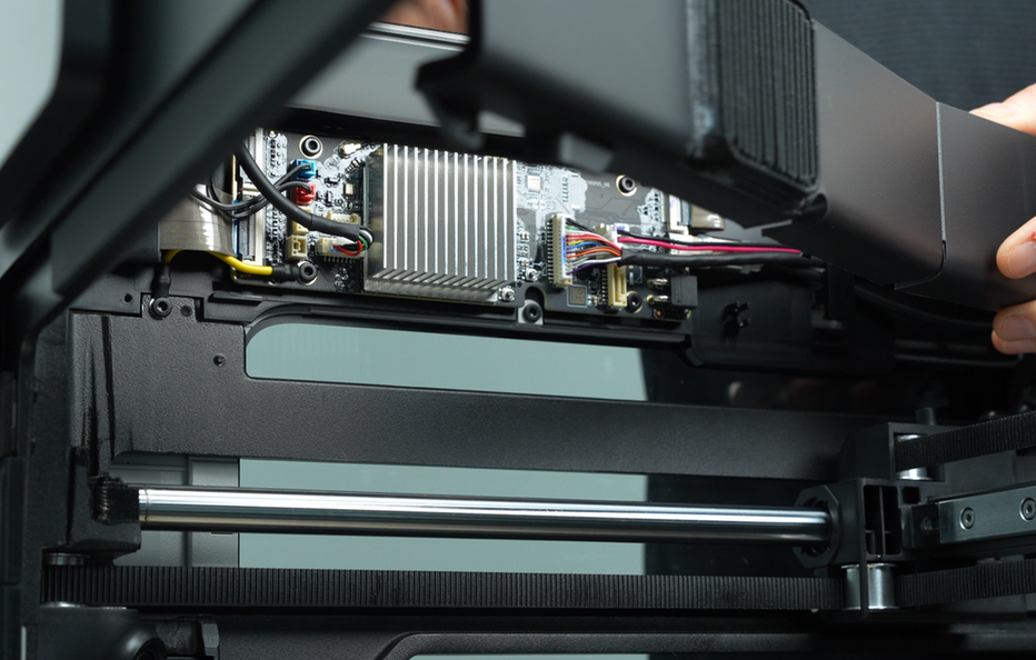
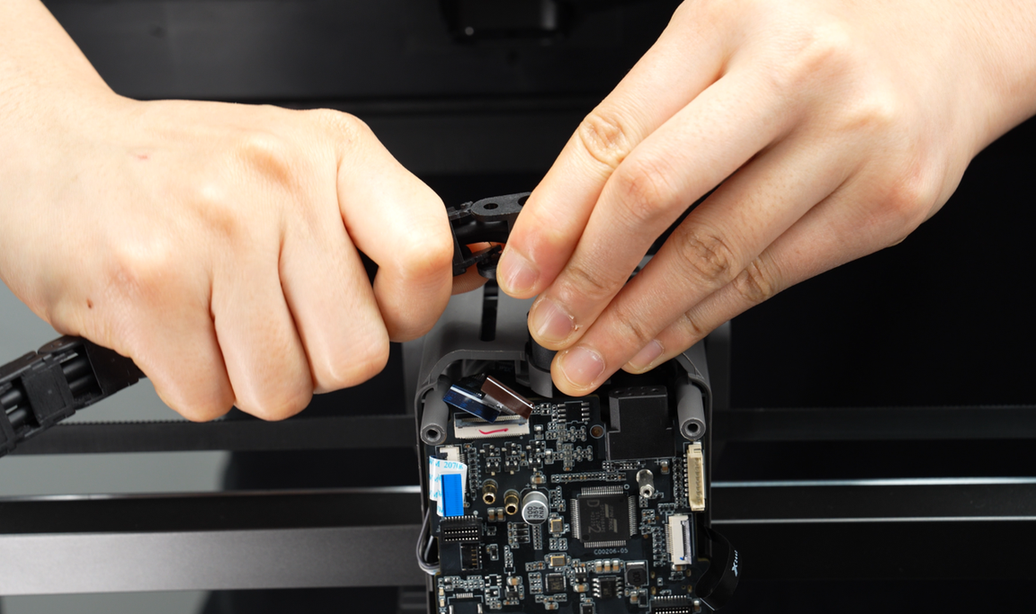
¶ Step 4: Disconnect cables on the TH Board
Disconnect all connectors on the TH board in sequence. Refer to the images and tables for the specific cable connectors and their connections.

| No. | Connected to | No. | Connected to |
|---|---|---|---|
| 1 | Extruder connection board - TH board FPC cable | 7 | Right eddy current coil |
| 2 | 3513 extruder servo motor | 8 | Nozzle camera |
| 3 | Toolhead sensor FPC cable | 9 | Toolhead camera |
| 4 | Left hotend heating assembly | 10 | Cooling fan for hotend |
| 5 | Left eddy current coil | 11 | Right hotend heating assembly |
| 6 | Lifting hall effect sensor |
There are three types of plugs on the TH board, and you can use different methods to disconnect depending on the type of plug.
-
Connectors 1, 2, 3, 6, 8, and 9 are secured by latches. Unlock the latch and remove the cable.
-
Connectors 5, 7, and 10 are secured from the front. Push the connector out along the plane.
-
Connectors 4 and 11 are secured by headers. Pull directly to disconnect.
- Note: 4 - The left hotend heating assembly has been removed in "Step 2".
The detailed steps to disconnect the connection wires on the TH board are as follows:
Detailed steps:
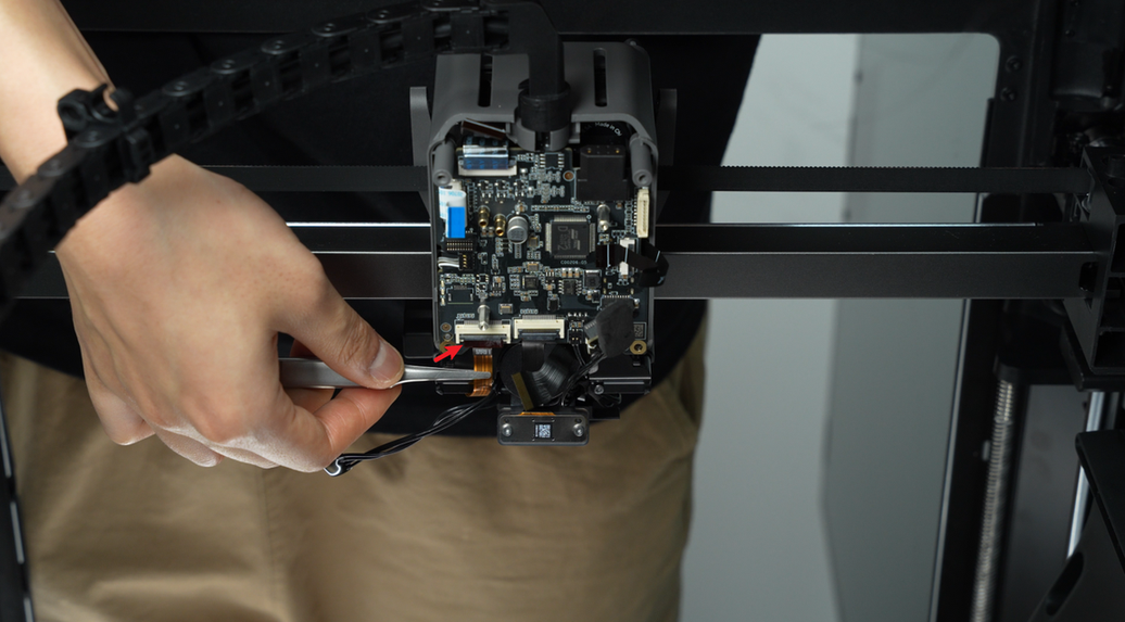
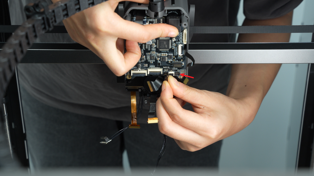
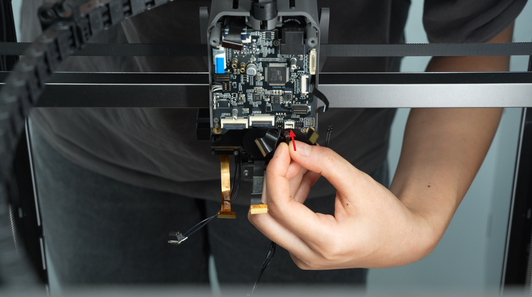
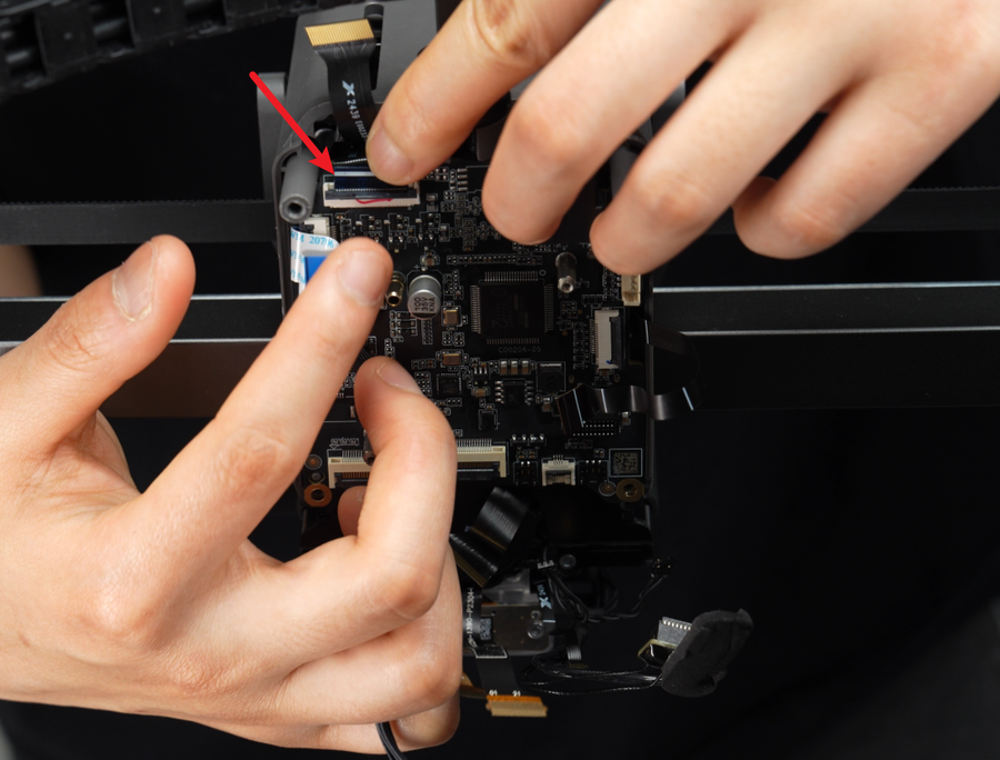
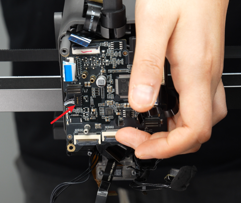
- Disconnect the right hotend heating assembly(No. 11) cable. Unlock the latch on the toolhead sensor FPC cable(No. 3) and remove the cable.
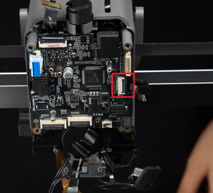
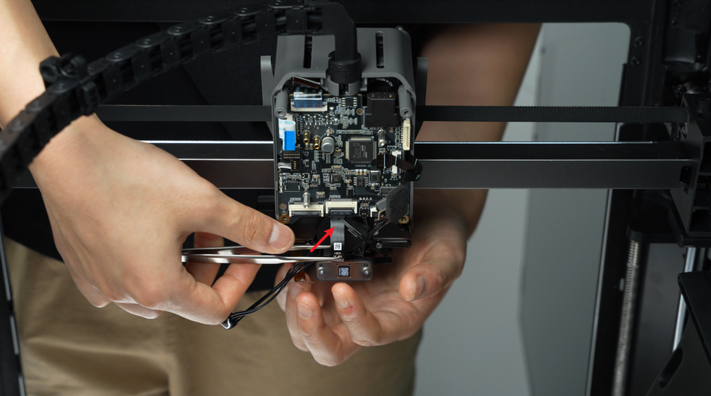
- Use tweezers to peel off the backing tape of the toolhead camera(No. 9) and nozzle camera(No. 8) FPC cables. Unlock the latch and remove the FPC cables.

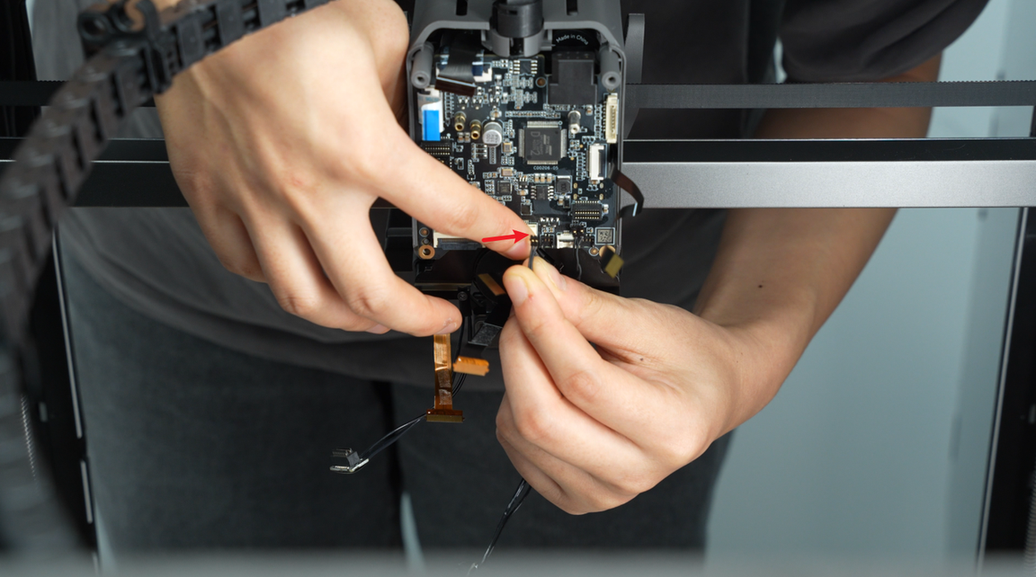
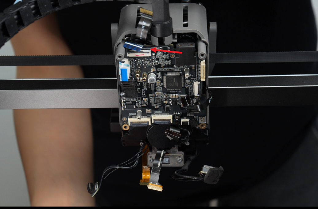
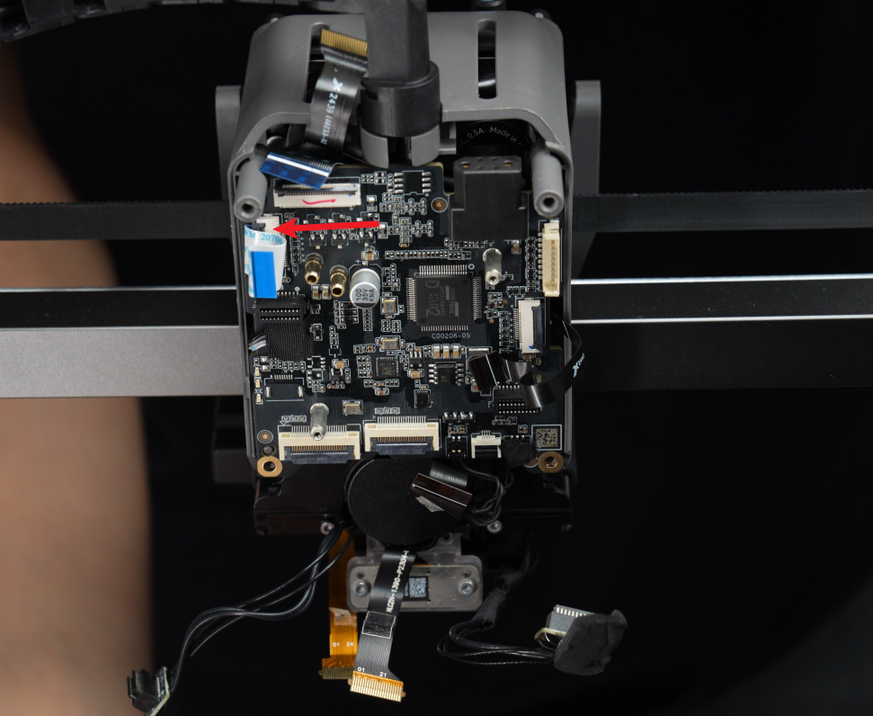
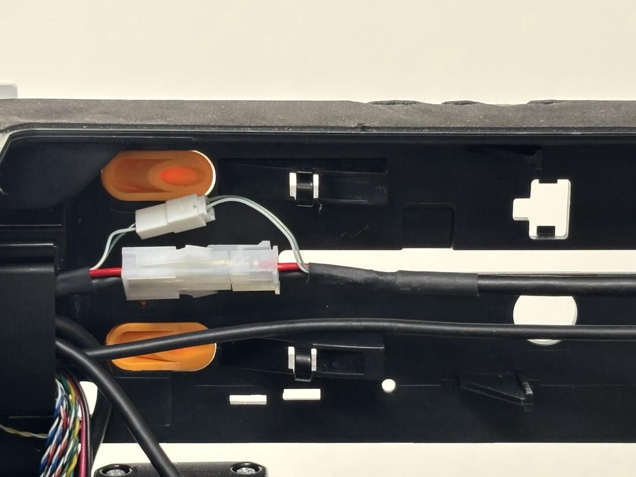
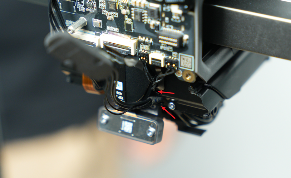
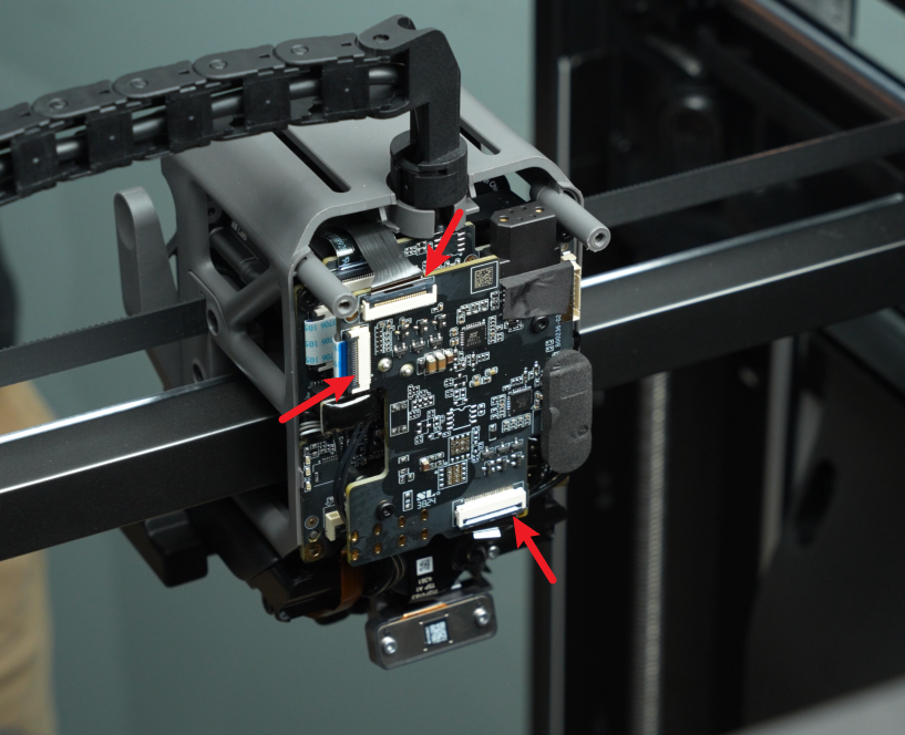
- As shown in the figure, there are two cable channels at the arrows. The large cable channel at the lower arrow is used to store the cables of the left hotend heating component, and the small cable channel at the upper arrow is used to organize the cables of the left eddy current coil plug, the right eddy current coil plug and the lifting hall plug. Before unplugging these three small plugs, you need to pull out the cables in the two cable channels in turn to increase the cable length and facilitate unplugging.
Remove the cables from the two cable channels in the following order:

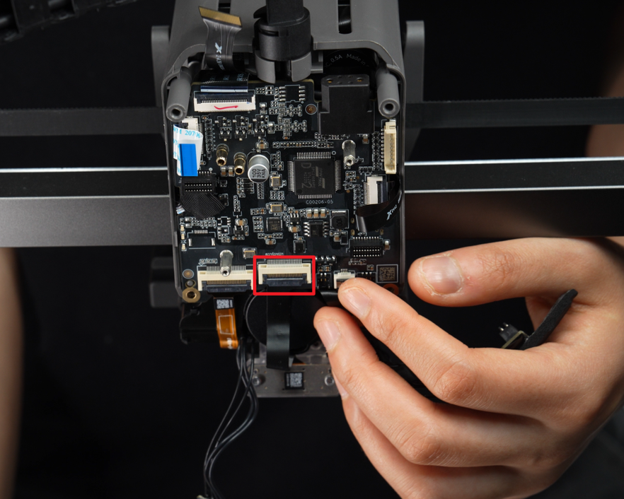
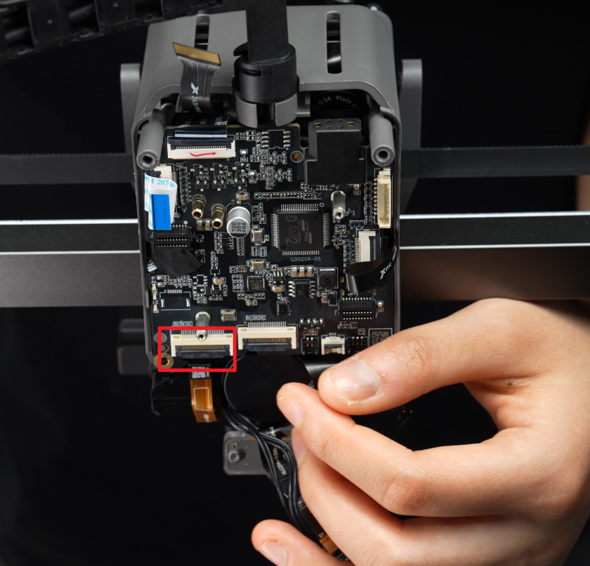
- Unlock the FPC interface and 3513 extruder servo motor(No. 2) interface latches. Remove the FPC cable and place it on the table (keep it safe for later installation). Take out the 3513 extruder servo motor cable from the latch.
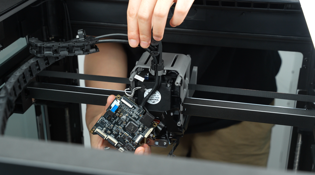
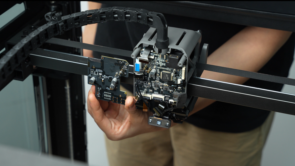
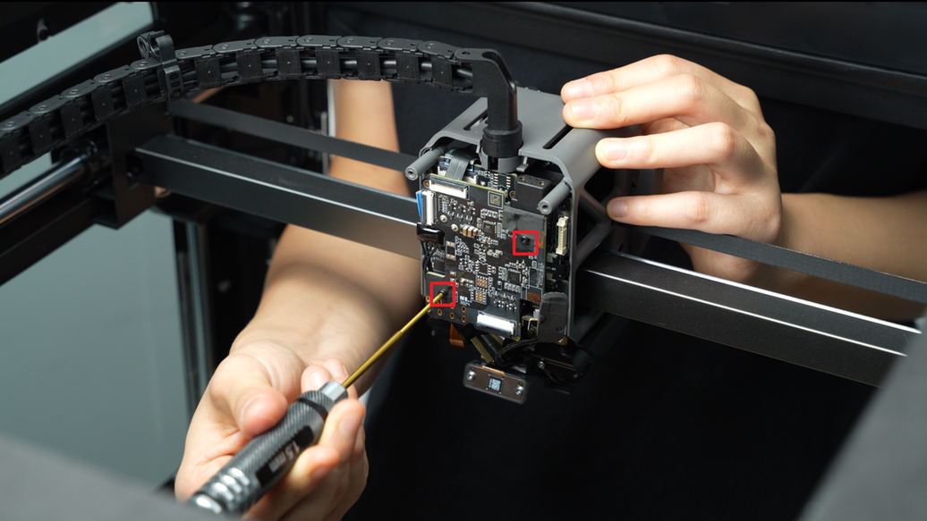
¶ Step 5: Remove the TH Board
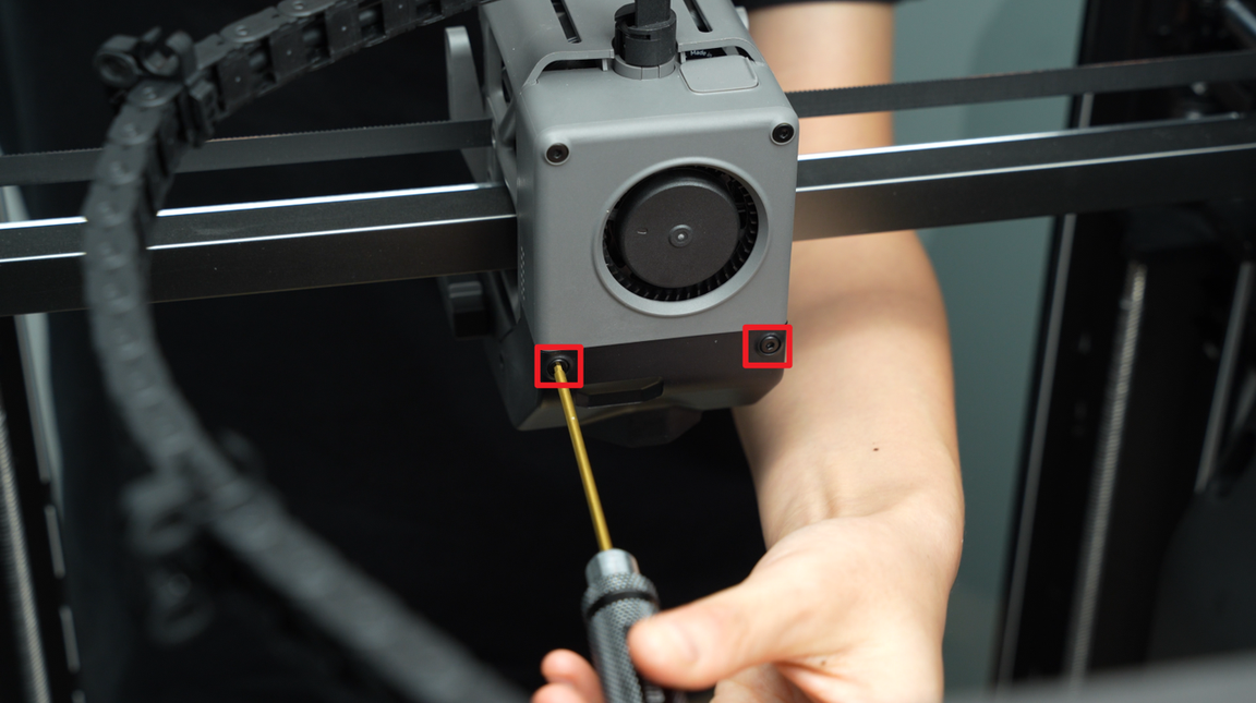
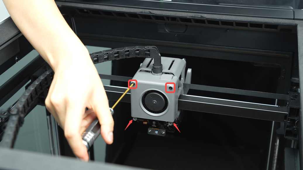
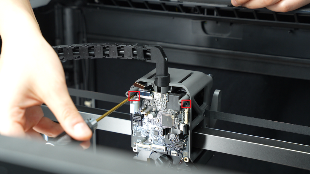
Use an H2.0 Allen Key to remove the two fixing screws (BT2.6x8).

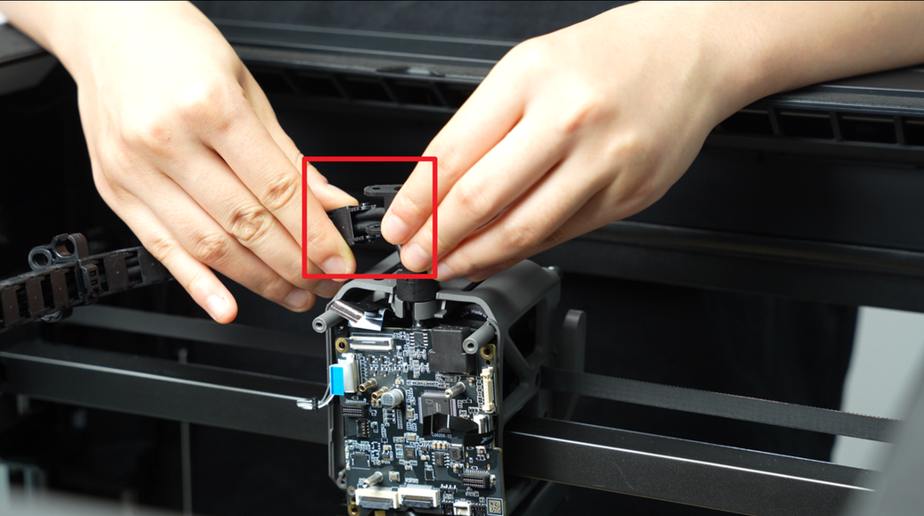
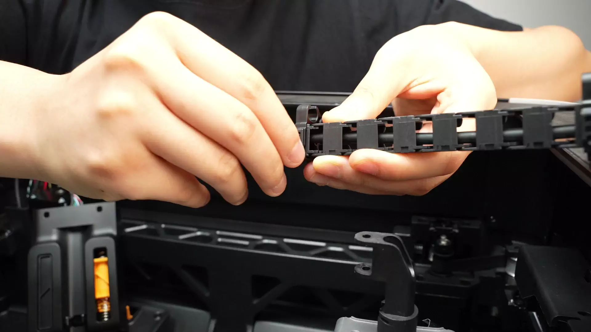
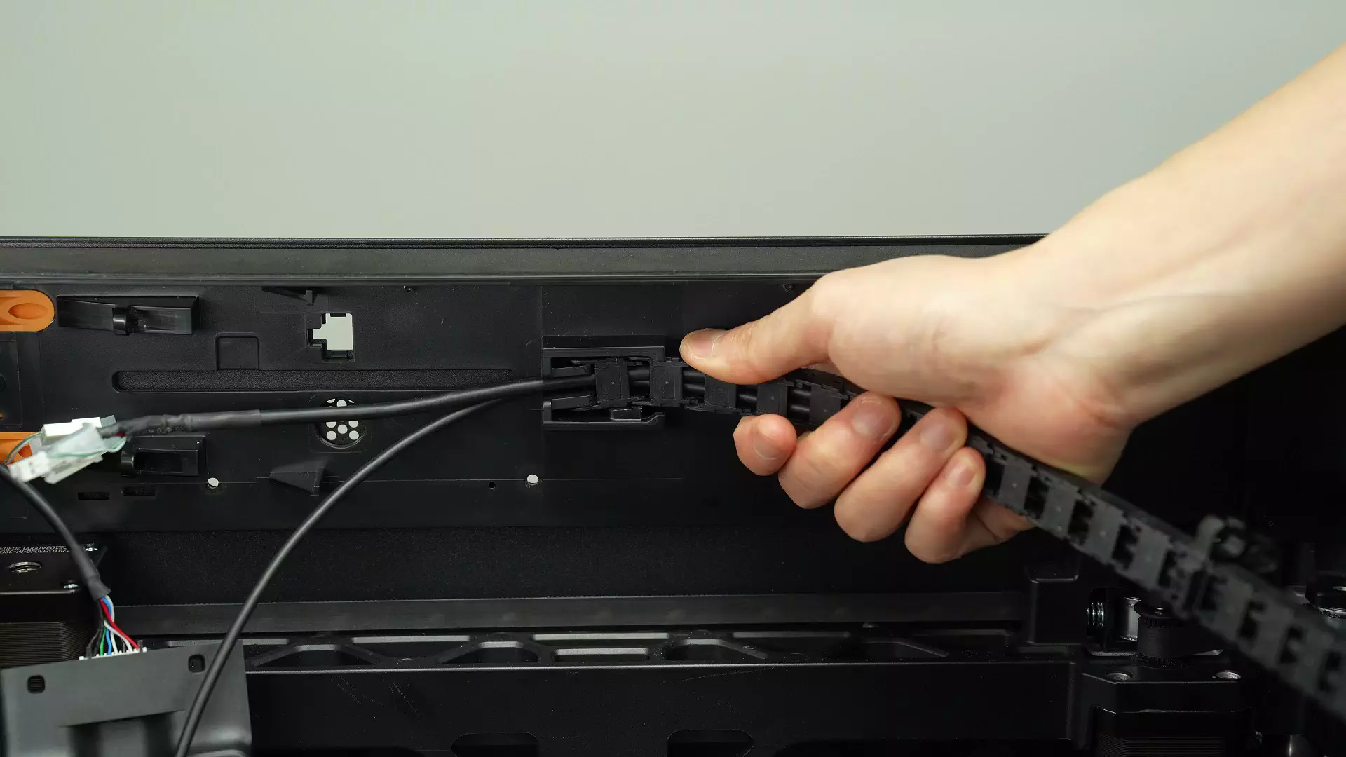
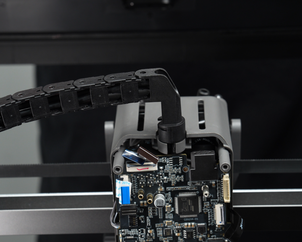
Disconnect the cable chain from the cable chain base;
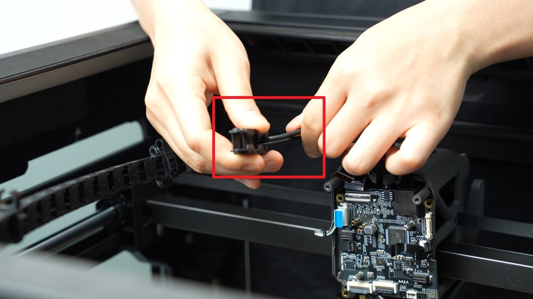
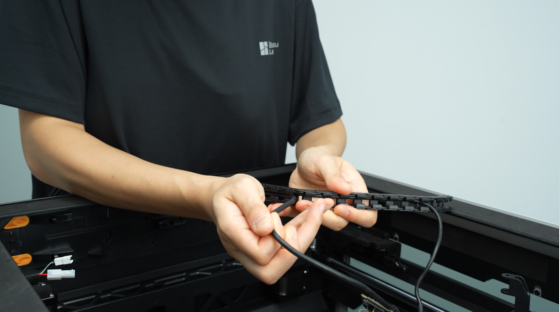
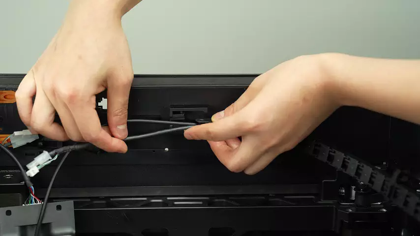
And pull out the MC-TH cable and USB-C cable from the cable chain.
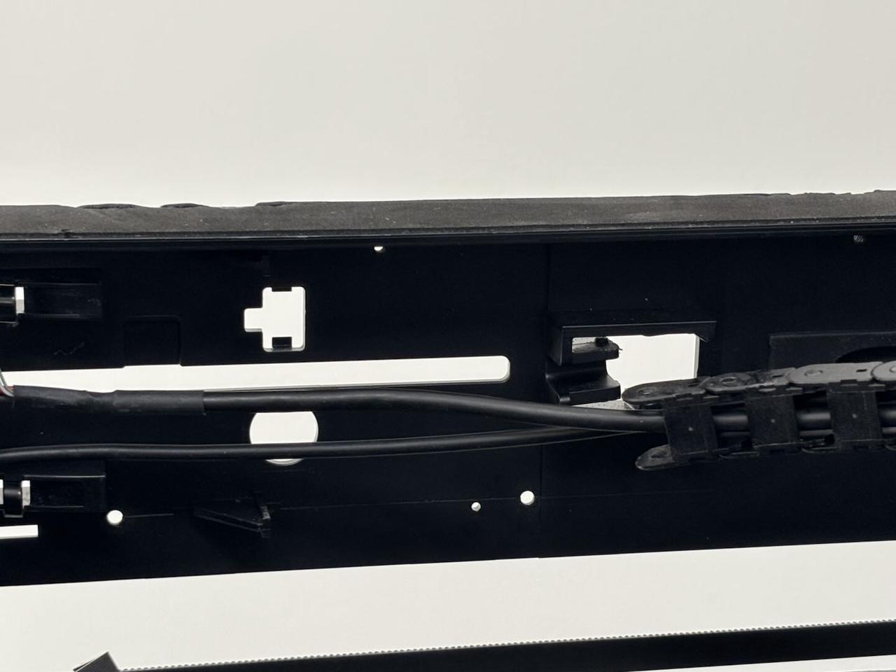
Rotate the cable chain base to align the notch with the notch on the toolhead middle housing.
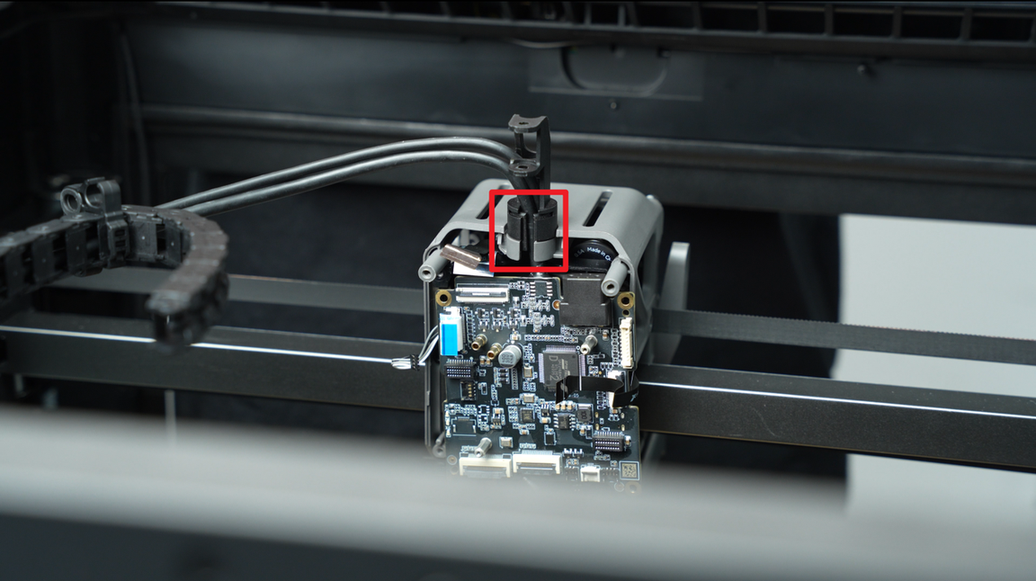
Pull the TH board slightly downward and remove the MC-TH cable and USB-C cable from the notch.

Disconnect the USB-C cable from the TH board.
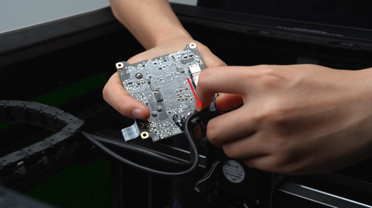
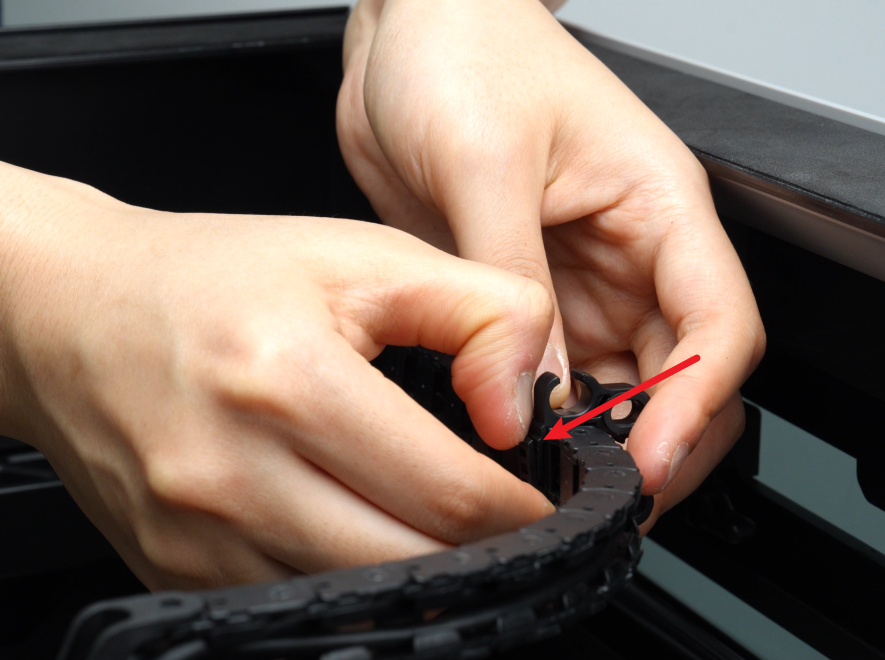
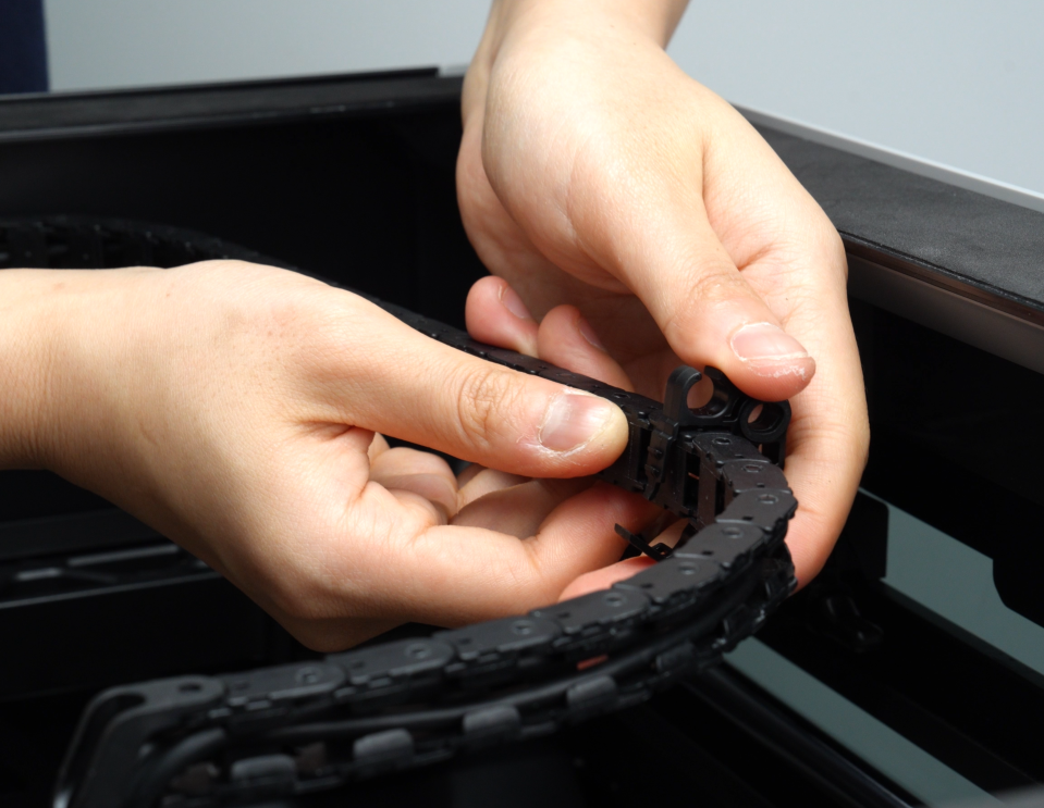
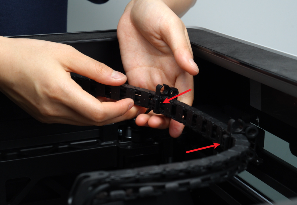
Unlock the two latches on the cable chain (located on the 8th and 18th links, counting from the toolhead side).
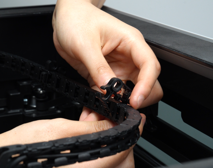
Disconnect the cable chain from the printer top cover and remove the MC-TH cable.
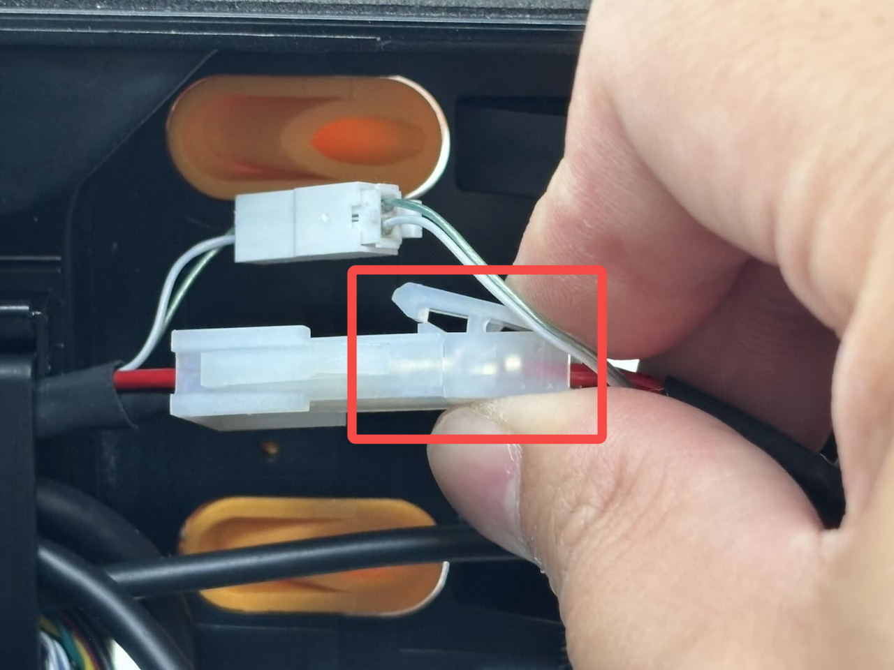
Press the latch on the MC-TH cable to disconnect it from the toolhead to MC board cable and remove the TH board.
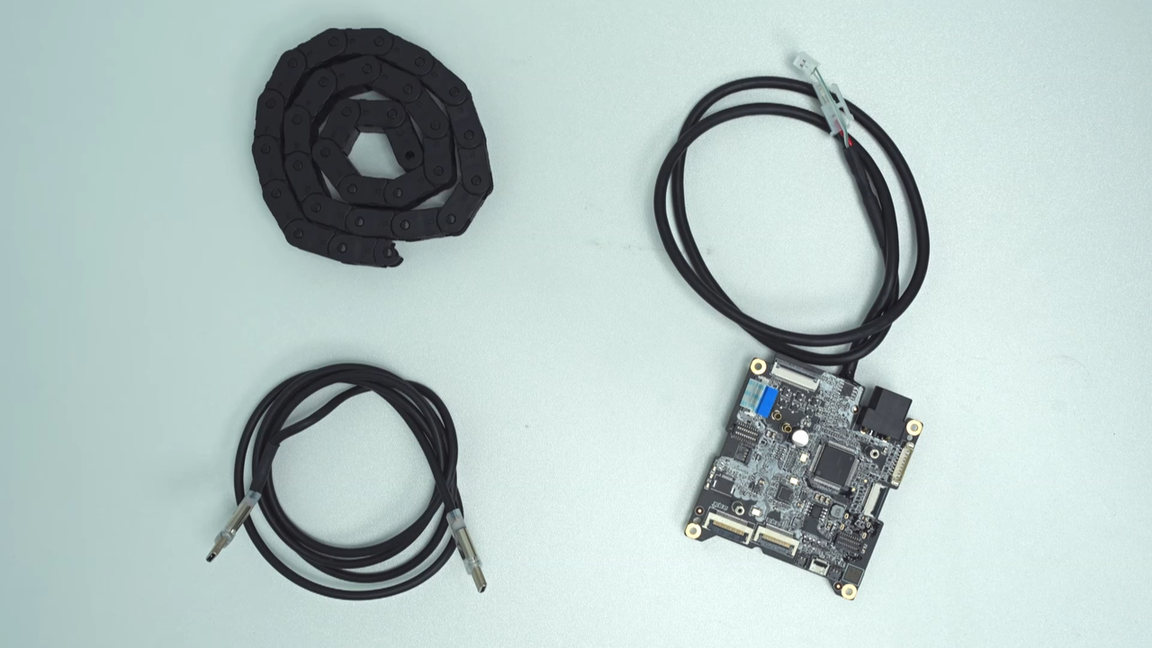
Pull out the USB-C cable and the MC-TH cable from the cable chain.Upon completing this step, you will have the USB-C cable, TH board, and cable chain separately.
 |
|
 |
¶ Install the Extruder Connection Board/TH Board/FPC Cable
¶ Step 1: Install the TH board
- Connect the new TH board to the toolhead to MC board cable and secure the cable into the cable chain. Reconnect the cable chain to the top cover.
- Connect the USB-C cable to the TH board.
Note: Ensure the "T" shape faces outward!
- Rotate the cable chain base to align the notch with the toolhead middle housing notch. Snap the MC-TH cable and USB-C cable into the cable chain base and toolhead middle housing. You can snap the thinner cable (USB-C cable) in first, then the thicker cable (MC-TH cable).

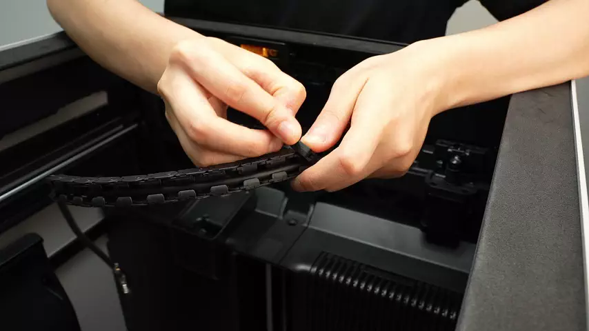
- Reconnect the cable chain to the cable chain base and reattach the latches (on the 8th and 18th links, counting from the toolhead side).
- Align the TH board with the screw holes on the toolhead. Use an H2.0 Allen Key to tighten the 2 fixing screws (BT2.6x8).
Note: Before tightening the screws, ensure no cables are trapped under the TH board!
Check the following cables:
From top to bottom and from left to right, the cables that need to be checked in turn include: 2004 switching motor, 3513 extruder servo motor, cooling fan for hotend, extruder connection board plug, toolhead sensor FPC cable, toolhead camera, nozzle camera, left and right eddy current coils, lifting hall and 2004 lifting motor cable, left and right hotend heating assemblies.

¶ Step 2: Reconnect cables
Reconnect all cables to the TH board in sequence. Refer to the images and tables for the specific cable connectors and their connection methods.
- Note: No. 1, 2, 3, 6, 8, 9 plugs are fixed by buckles. You need to insert the cable into the interface of the TH board and tighten the buckle after the cable is fully inserted;
| No. | Connected to | No. | Connected to |
|---|---|---|---|
| 1 | Extruder connection board - TH board FPC cable | 7 | Right eddy current coil |
| 2 | 3513 extruder servo motor | 8 | Nozzle camera |
| 3 | Toolhead sensor FPC cable | 9 | Toolhead camera |
| 4 | Left hotend heating assembly | 10 | Cooling fan for hotend |
| 5 | Left eddy current coil | 11 | Right hotend heating assembly |
| 6 | Lifting hall effect sensor |
No. 1 - FPC cable

No. 2 - 3513 extruder servo motor
No. 3 - Toolhead sensor FPC cable
No. 6 - Lifting hall effect sensor

No. 8 - Nozzle camera
No. 9 - Toolhead camera
Reattach the toolhead camera and nozzle camera FPC cables. Use tweezers to secure the cables back onto the toolhead.

- Connectors No. 5, 7, and 10 are secured from the front. Ensure the metal side of the connector faces upward, align the connector with the interface, and press downward to disconnect.
No. 10 - Cooling fan for hotend
No. 5 - Left eddy current coil

No. 7 - Right eddy current coil

- Connectors No. 4 and 11 are secured by headers. Align the header with the connector and insert it directly, ensuring it is fully seated.
Insert the cables into the cable clip:
As shown in the figure, there are 2 cable channels at the arrows. The large cable channel at the lower arrow is used to store the left hotend heating assembly cable, and the small cable channel at the upper arrow is used to organize the left eddy current coil plug, right eddy current coil plug and lifting hall plug cables. You can reconnect these 3 plugs to the TH board and then re-insert the cables into the small cable channel.
The order of inserting the cables is:
¶ Step 3: Install the filament buffer and AP board cover
- Install the filament buffer:
You can refer to this Wiki for instructions: Replace H2D Filament Buffer
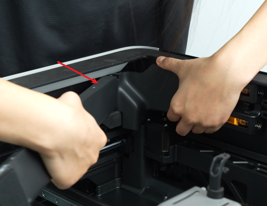
- Install the AP board cover:
First, snap the AP board cover back from the side close to the back of the printer, press the 2 places indicated by the arrows into place, flush with the filament buffer on the right side and flush with the cable cover on the bottom, and then tighten a fixing screw (BT2.6x8) with an H2.0 Allen key.
¶ Step 4: Install the extruder connection board
- Align the extruder connection board latches with the slots on the TH board.
- Install the extruder connection board and tighten the 2 fixing screws (M1.6x4) using an H1.5 Allen Key.
- Reconnect the following cables to the extruder connection board:
The name of the cable that corresponds to the number in the picture:
- FPC cable
- 2004 switching motor cable
- Part cooling fan cable (to be connected in Step 5)
- Left hotend heating assembly cable
- 2004 lifting motor cable
Detailed Steps:
- Connect the left hotend heating assembly to the TH board. Insert the header into the TH board’s socket and secure the foam onto the extruder connection board.
- For No. 1, 2, and 5, these plugs are fixed by buckles. You need to insert the cable into the interface of the extruder connection board, and then tighten the buckle after the cable is fully inserted;
NOTE: No. 3 - The part cooling fan connector will be connected in "Step 5".
¶ Step 5: Install the part cooling fan and air duct
You can refer to this Wiki for instructions: How to replace the H2D part cooling fan
¶ Verify the Functionality
¶ Check the indicator lights on the control board
Normal State: The TH board indicator light stays on (top & middle) and flashes rapidly (bottom).
Before tightening all screws, you may temporarily install or leave the cover off (be cautious of electrical safety and operate with the power disconnected). Then power on to check whether the indicator lights are functioning normally. If the lights are normal, fasten the screws to avoid rework.
https://public-cdn.bblmw.com/wiki/H2D/TH1.mp4
¶ Connect the power cable and turn on the power. Initiate a print and check if there is an error.
Connect the power supply, turn on the printer and initiate a print to check if you can print successfully.
If you encounter any problems, first retrace your steps and check all connections to try again. If the problem persists, please contact the Bambu Lab service team for further assistance.
¶ End Notes
We hope the detailed guide provided has been helpful and informative.
If this guide does not solve your problem, please submit a technical ticket, we will answer your questions and provide assistance.
If you have any suggestions or feedback on this Wiki, please leave a message in the comment area. Thank you for your support and attention!