¶ AP board
The full name of AP board refers to the Application Processor Main Board, which is the power board that processes information interaction in the printer. It provides an independent operating environment for the printer and supports all system functions required by printer applications, including memory management, system firmware, graphics processing, and multimedia decoding.
In this guide we will show the process of removing the AP board, and installing a new one.
The AP board spare parts include:
-
AP board * 1
-
BT3x5 screws - used to fix the AP board * 4
¶ When to use
It is necessary to contact Bambu Lab Technical Support to determine if the problem the printer has experienced is due to the AP board.
¶ Tools and materials needed
-
New AP board
-
H2.0 Allen key
After our verification, removing the ground wire has no effect on functionality. Some versions include the ground wire, while others do not, resulting in two versions coexisting. Please refer to the version you received to determine whether it is necessary to remove the ground wire from the AP board.
¶ Safety Warning
IMPORTANT!
It's crucial to power off the printer before conducting any maintenance work, including work on the printer's electronics and tool head wires. Performing tasks with the printer on can result in a short circuit, leading to electronic damage and safety hazards.
During maintenance or troubleshooting, you may need to disassemble parts, including the hotend. This exposes wires and electrical components that could short circuit if they contact each other, other metal, or electronic components while the printer is still on. This can result in damage to the printer's electronics and additional issues.
Therefore, it's crucial to turn off the printer and disconnect it from the power source before conducting any maintenance. This prevents short circuits or damage to the printer's electronics, ensuring safe and effective maintenance. For any concerns or questions about following this guide, we recommend submitting a technical ticket regarding your issue and we will do our best to respond promptly and provide the assistance you need.
¶ Remove the AP board
¶ Step 1: Turn off the power
After turning off the printer, unplug the power cable and remove the glass cover plate.
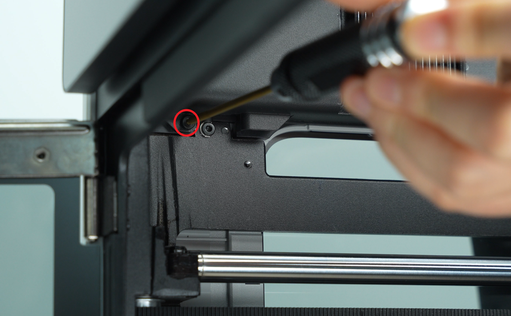
¶ Step 2: Remove the AP board cover
If you find it difficult to remove and install the AP board cover, you can refer to the relevant video steps in this wiki section to assist you. click here
Use an H2.0 Allen key to loosen 1 fixing screw (BT2.6x8), and then remove the AP board cover from the side near the front door.
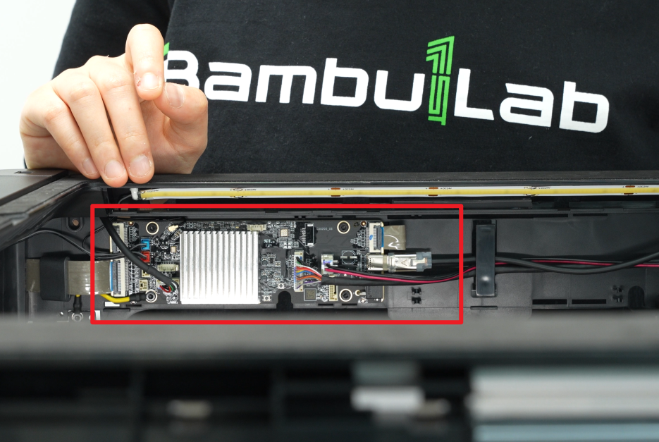
¶ Step 3: Disconnect the cables
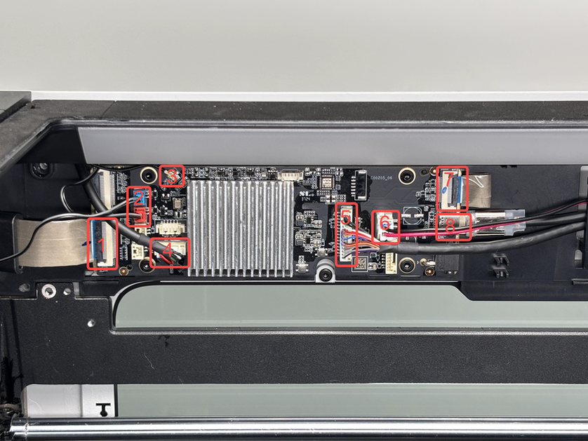
Unplug the connection cables on the AP board one by one.
If the USB-C cable is difficult to unplug, wait until the screws are removed before unplugging it.
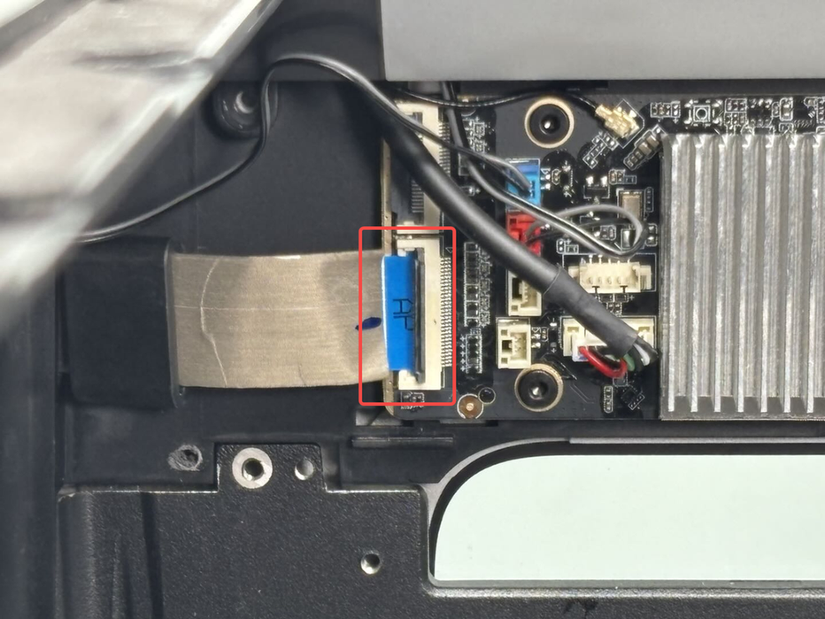
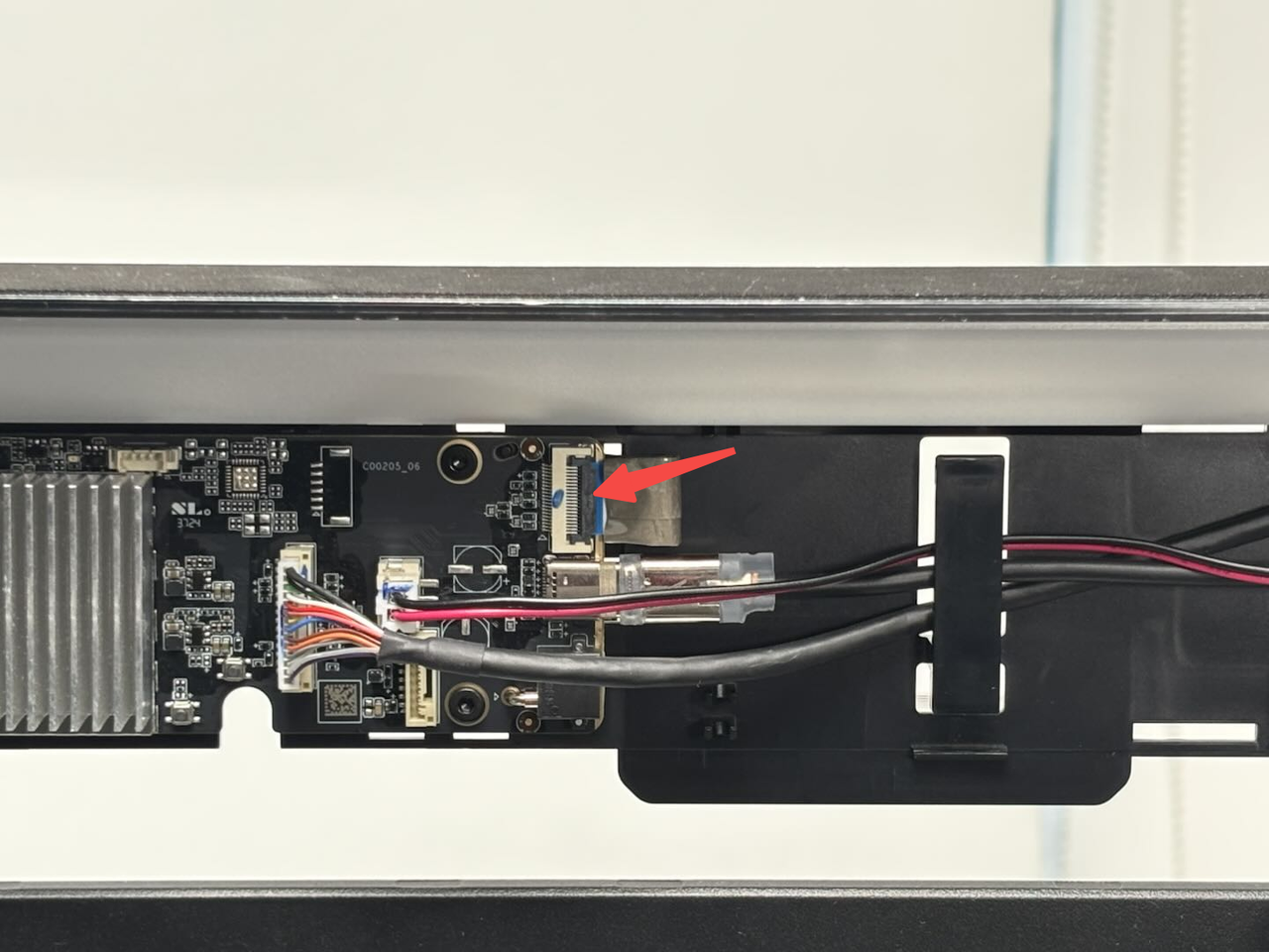
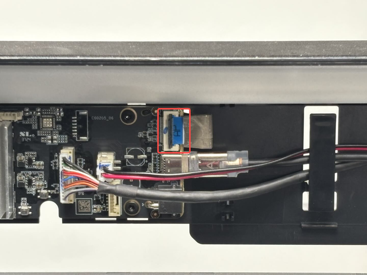
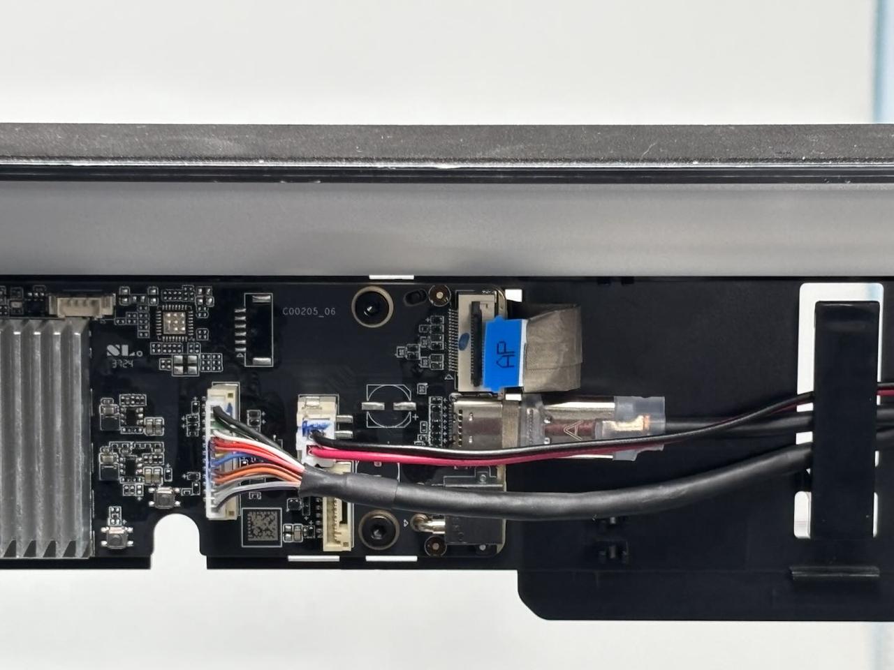
- Screen FPC:
You can unscrew the buckle on the screen FPC and pull it out.
- Left and right LED light connectors(Blue:right LED light;Red:left LED light):
You can press the buckle of the LED light cable connector and then pull out the connectors.
The left/right LED light connectors (red/blue) can be pulled out in the same way.
- Wifi antenna:
You can unlock the Wifi antenna by simply pulling the buckle of the Wifi antenna outwards.
- USB port board:
You can unlock the USB port board connector by simply pulling the buckle of the connector outwards.
- MC-AP cable(communication):
You can unlock the MC-AP cable by simply pulling the buckle of the cable outwards.
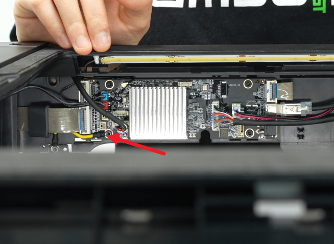
- MC-AP cable(power supply):
You can unlock the MC-AP cable by simply pulling the buckle of the cable outwards.
- Live view camera connector:
Unfasten the buckle that connects the live view camera connector to the AP board, and then remove the live view camera connector from the interface on the AP board;
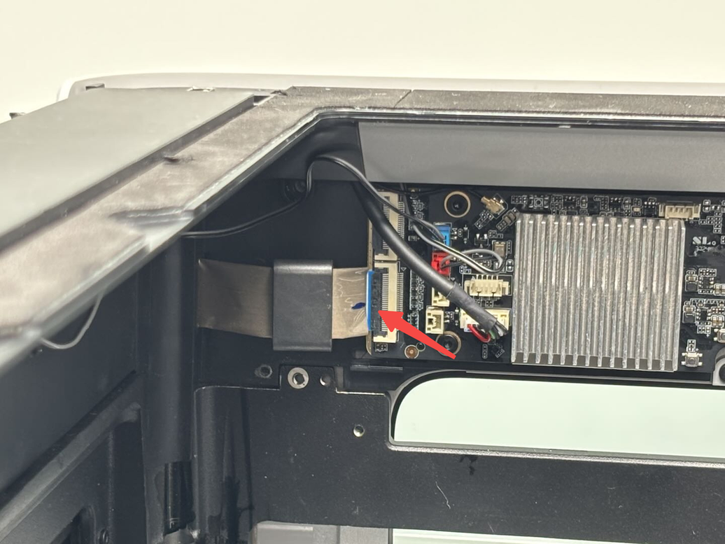
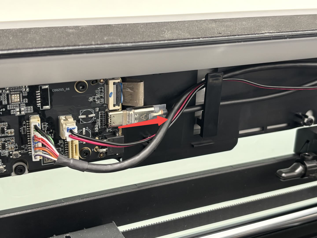
- USB-C cable
Unplug the USB-C cable parallel to the AP board.
After our verification, removing the ground wire has no effect on functionality. Some versions include the ground wire, while others do not, resulting in two versions coexisting. Please refer to the version you received to determine whether it is necessary to remove the ground wire from the AP board.
If your AP board has a ground wire at the bottom left fixing screw, you can separate the ground wire from the AP board when you remove the AP board fixing screw.
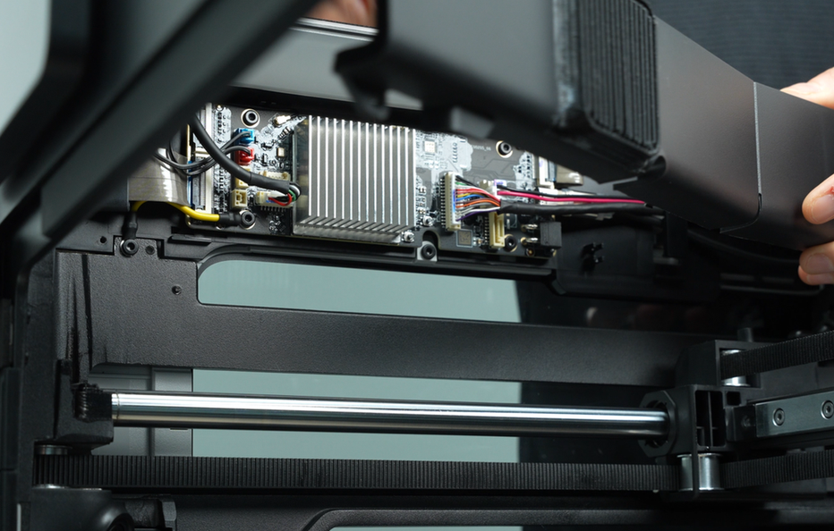
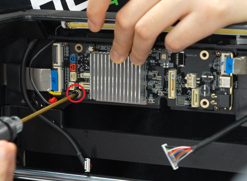
¶ Step 4: Remove the AP board
Use an H2.0 Allen key to loosen the 4 fixing screws (BT3×5), and then remove the AP board.

¶ Install the AP board
¶ Step 1: Reinstall the AP board
Align the AP board with the screw holes on the upper frame and tighten the 4 fixing screws (BT3x5) using an H2.0 Allen key.

If your AP board has a ground wire at the fixing screw in the lower left corner, you can lock the ground wire and the AP board together when installing the fixing screw in the lower left corner of the AP board.
¶ Step 2: Connect the cables
Reinstall the connection cables on the AP board one by one.
To avoid interference when connecting the cables, you can connect the cables in two parts:
-
For the left cables, connect them in this order: 1 -> 2 (blue -> red) -> 3 -> 4;
-
For the right cables, connect them in this order: 7 -> 8 -> 6 -> 5.
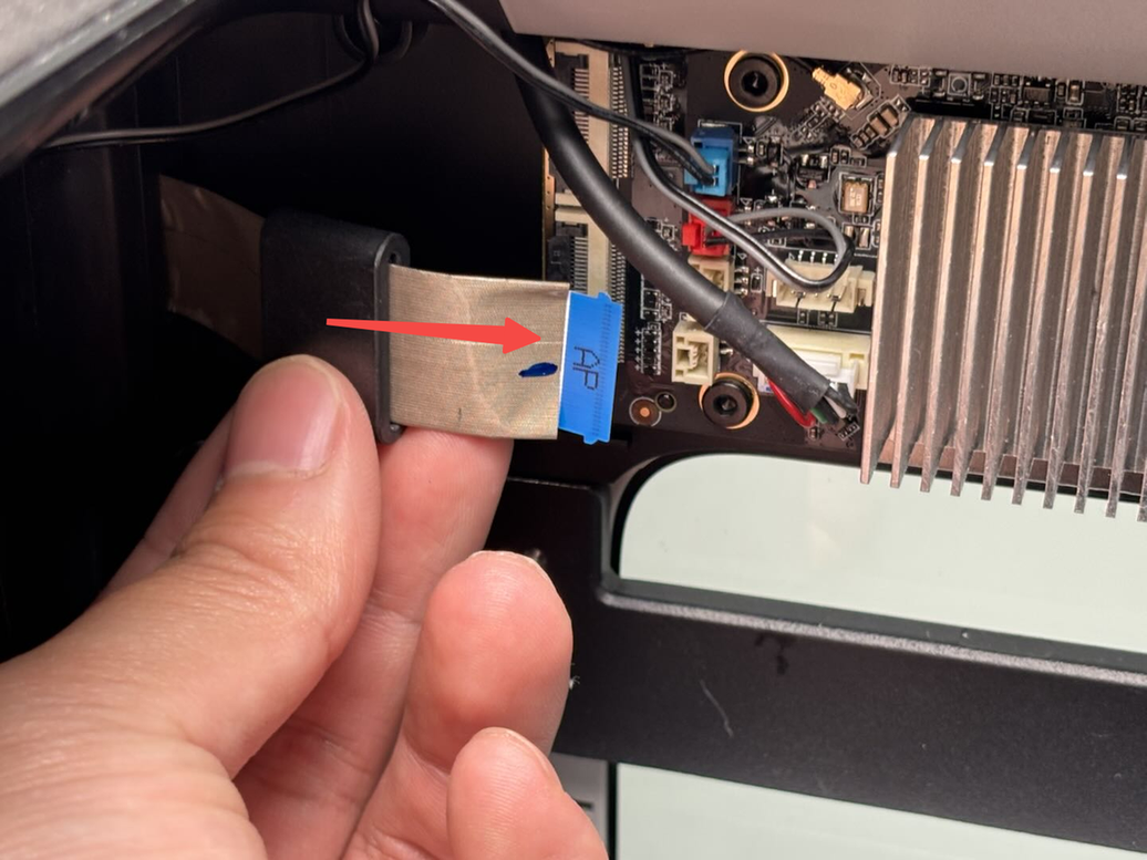
Note: When connecting the USB-C cable, make sure that the A side faces outward.

-
Screen FPC
-
Left and right LED connector (blue: right LED light; red: left LED light)
-
Wifi antenna
-
USB port board
-
MC-AP cable (communication)
-
MC-AP cable (power supply)
-
Live view camera connector
-
USB-C cable
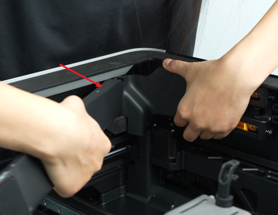
¶ Step 3: Reinstall the AP board cover
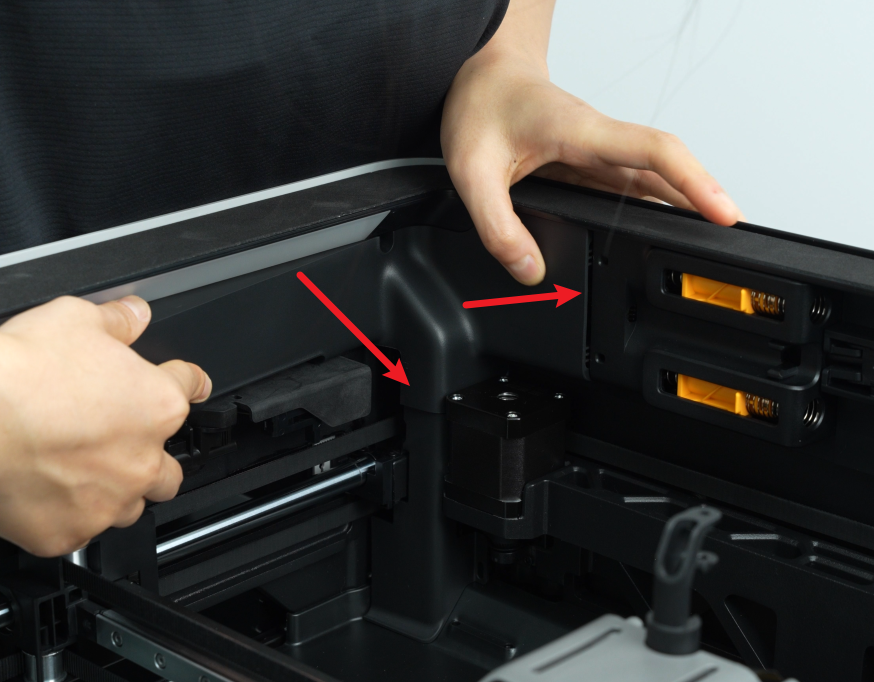
Note: Before installing the AP board cover, it is necessary to check whether the cables are obstructing the PTFE piping. Avoiding such obstruction will prevent any interference with the subsequent installation of the PTFE piping.
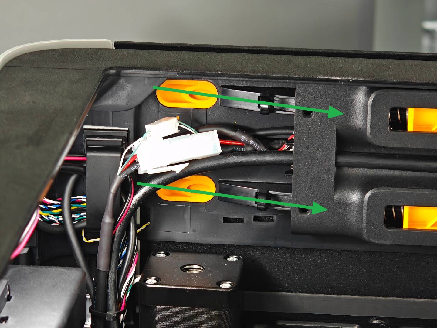
First, snap the AP board cover back from the side close to the back of the printer, press the two places indicated by the arrows into place, flush with the buffer on the right side and flush with the cable cover on the bottom, and then tighten a fixing screw (BT2.6x8) using an H2.0 Allen key.

¶ Verify the Functionality
¶ Check the indicator lights on the control board
Normal State: The AP board indicator light flashes rapidly (left) and stays on (right).
You can look through the grill, not to remove the AP board cover and observe the indicator lights through the heat dissipation holes of the AP board cover at a specific angle.
https://public-cdn.bblmw.com/wiki/H2D/AP4.mp4
If it is not clear, to remove the plastic cover to see it better.
https://public-cdn.bblmw.com/wiki/H2D/AP1.mp4
¶ Connect the power cable and turn on the power. Initiate a print and check if there is an error.
If errors occur, check if all cables on the AP board are properly connected and try again. If the problem persists, contact Bambu Lab technical support for further assistance.
Note:
- For printers with replaced AP boards, skip the step of binding the printer when starting for the first time.
Since the new SN is not activated, the binding operation cannot be performed. Binding can only be successful after the SN is activated.
- After confirming that the replacement is completed, the SN needs to be replaced. Please contact Bambu Lab technical support and provide both the new and old SN to complete the SN replacement.
¶ Appendix
Specifications and quantities of screws required to replace the H2D AP board (it is recommended to keep the removed screws properly to avoid loss):
| Specification | Image | Use | Position | Quantity | |
|---|---|---|---|---|---|
| BT2.6x8 | Fix the AP board cover |  |
1 | ||
| BT3x5 | Fix the AP board | 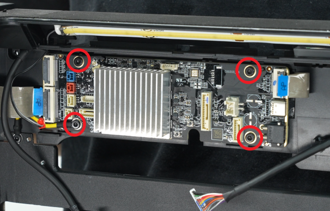 |
4 |
¶ End Notes
We hope the detailed guide provided has been helpful and informative.
If this guide does not solve your problem, please submit a technical ticket, we will answer your questions and provide assistance.
If you have any suggestions or feedback on this Wiki, please leave a message in the comment area. Thank you for your support and attention!