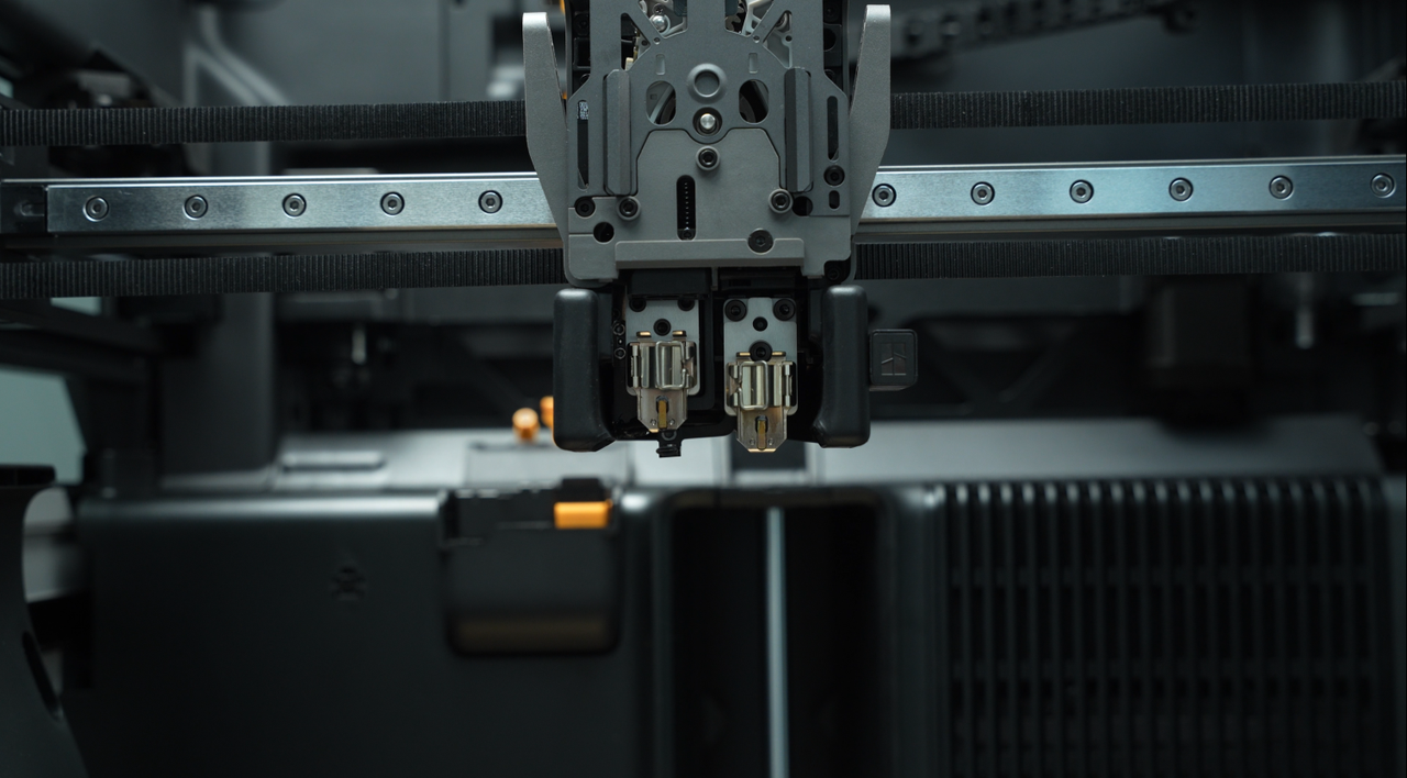
¶ Dual Extruder Unit
The extruder is responsible for pulling filament from the spool and feeding it into the hotend. The filament is heated and melted in the hotend, then extruded through the nozzle to create the printed model.
The extruder must precisely control the extrusion and retraction of the filament to ensure dimensional accuracy and surface quality of the printed model. It is one of the core components of a 3D printer.
 |
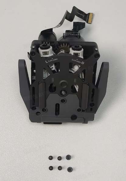 |
The spare parts for the dual extruder unit include the following:
-
Dual extruder unit (including extruder servo motor) * 1
-
BT2.6x8 screws * 2
-
M2.5x8 screws * 4
¶ When to use
-
The extruder is damaged.
-
The extruder servo motor is malfunctioning.
¶ Tools and materials needed
-
New dual extruder unit
-
H2.0 Allen key
-
Tweezers
Specifications and quantities of screws involved in replacing the H2D dual extruder unit (it is recommended to keep the removed screws properly to avoid loss):
| Specification | Image | Use | Position | Quantity | |
|---|---|---|---|---|---|
| BT3x8 | Fix the part cooling fan air duct | 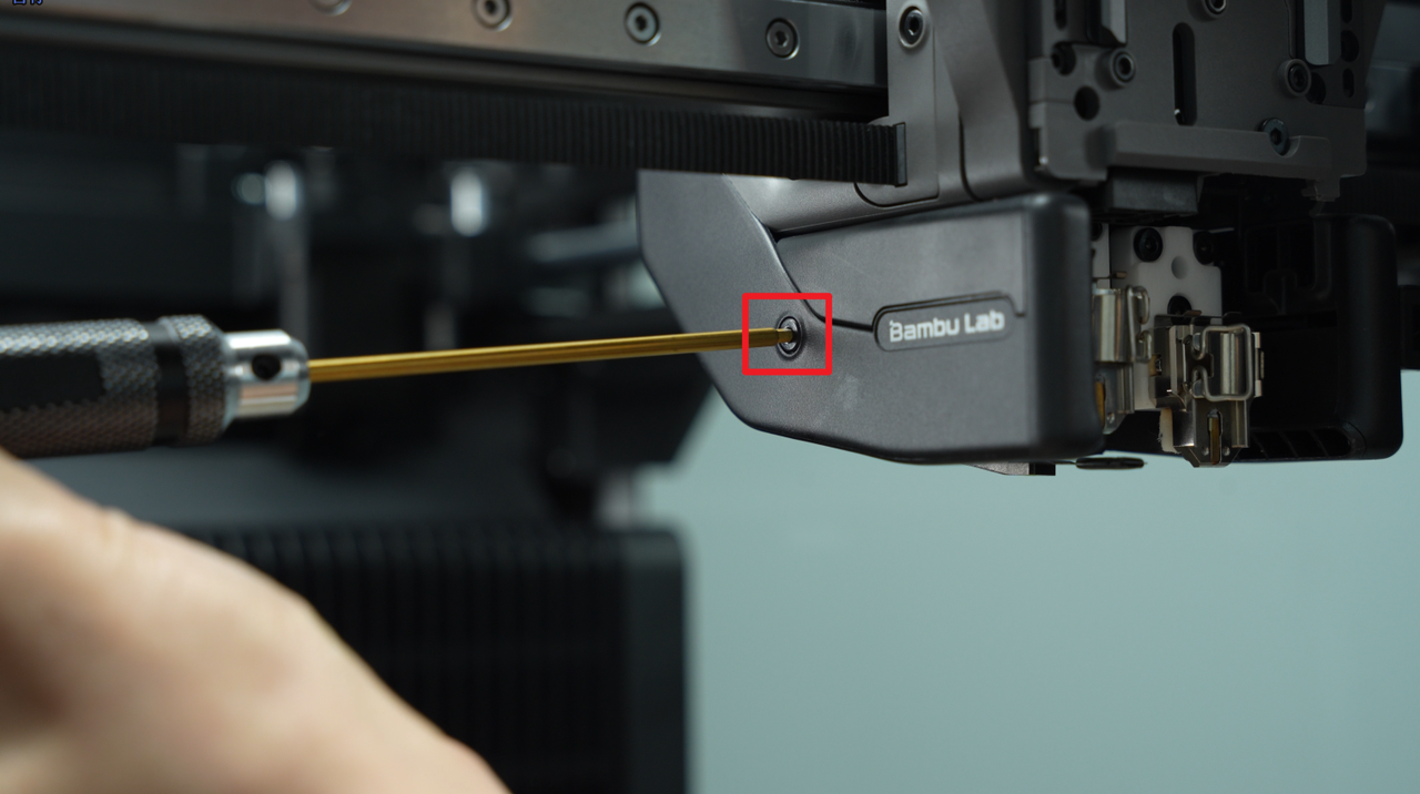 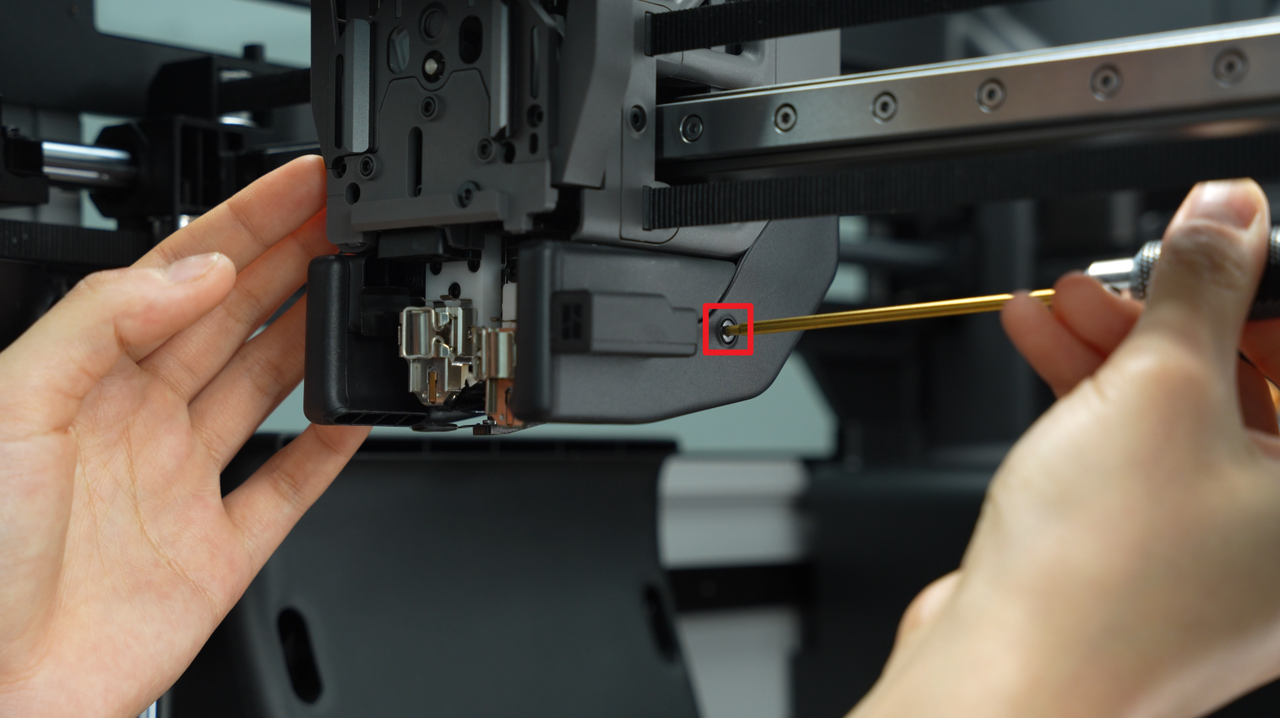 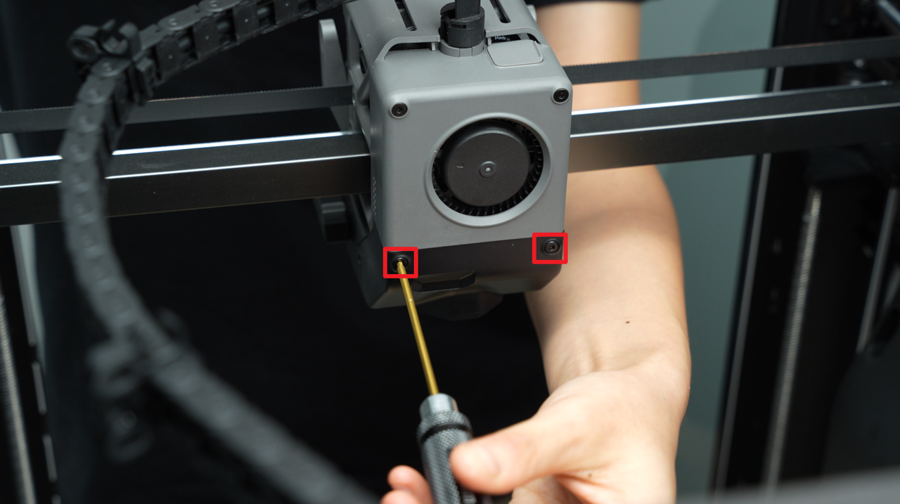 |
4 | ||
| BT3x20 | Fix the part cooling fan | 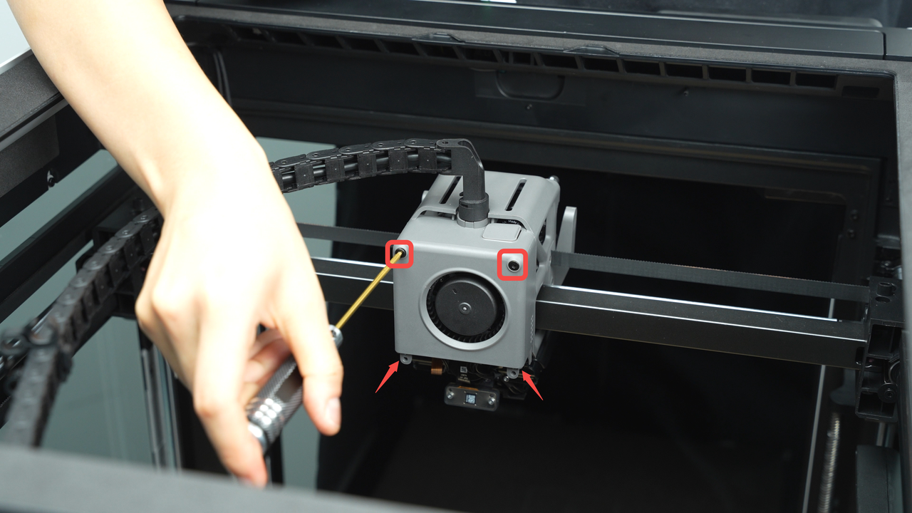 |
2 | ||
| BT2.6x8 | Fix the part cooling fan | 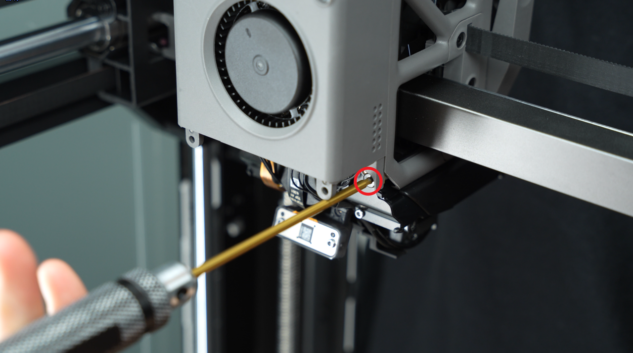 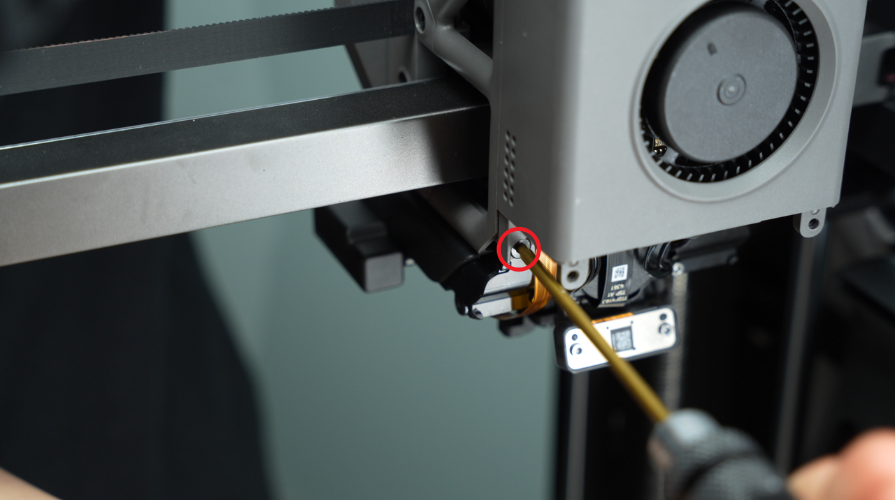 |
2 | ||
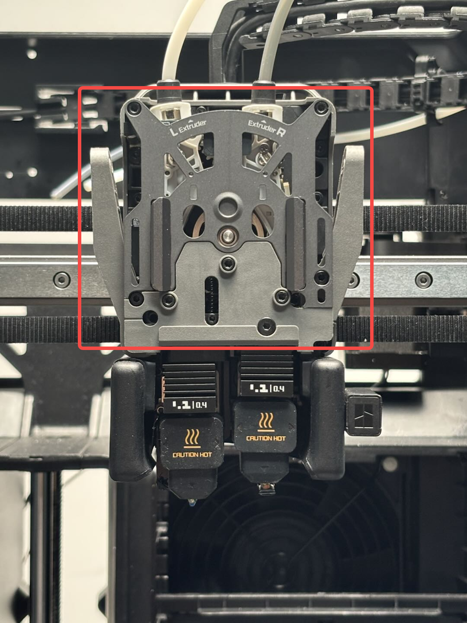
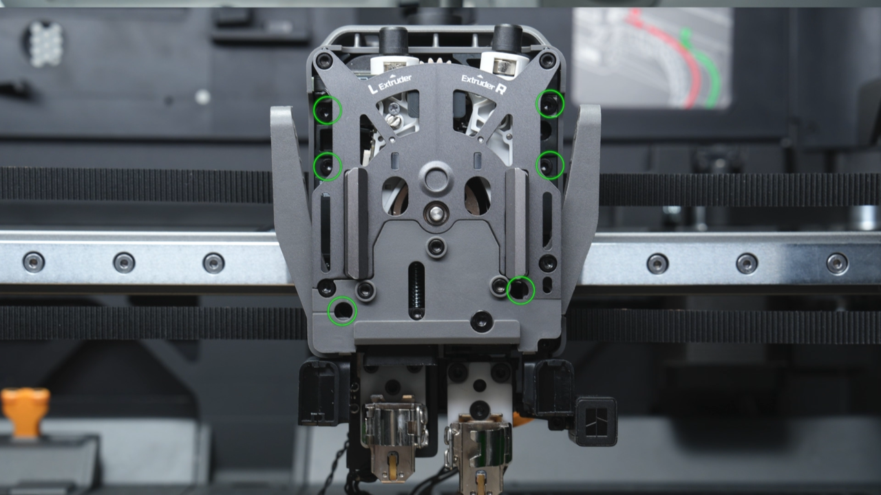
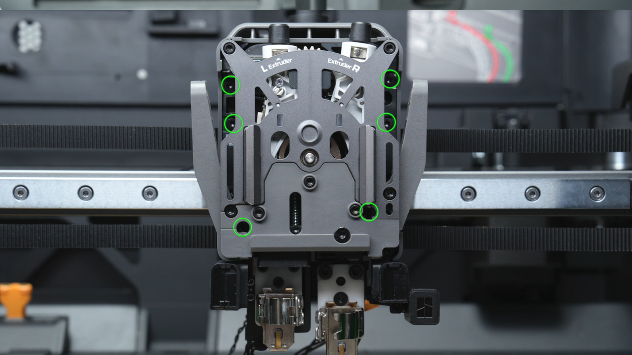
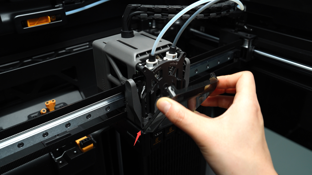
| Fix the extruder (marked by the red circle) |  |
2 | |||
| M2.5x8 | Fix the extruder (marked by the green square) | 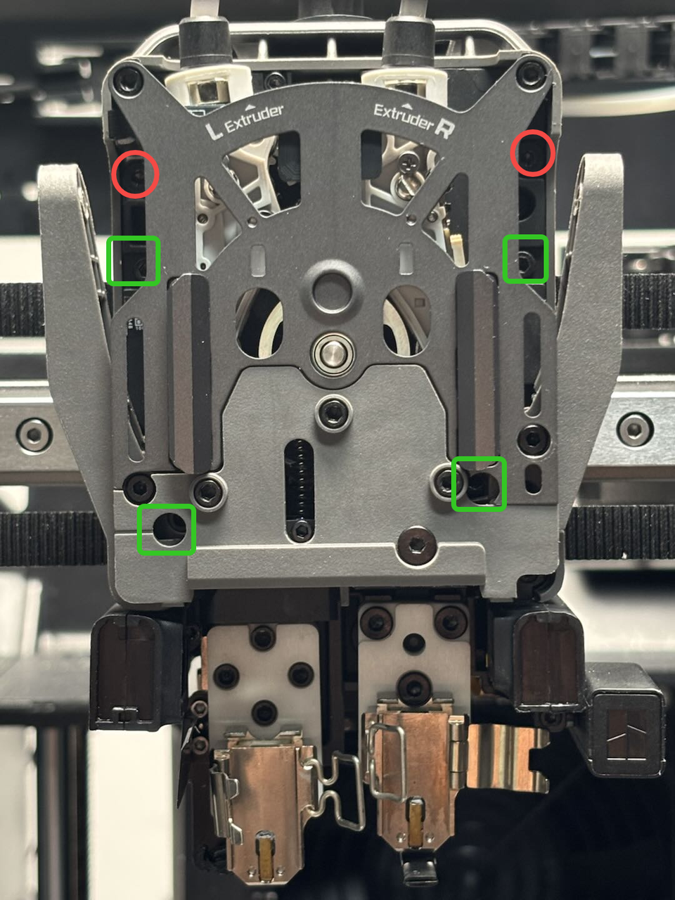 |
4 |
¶ Safety Warning
IMPORTANT!
It's crucial to power off the printer before conducting any maintenance work, including work on the printer's electronics and tool head wires. Performing tasks with the printer on can result in a short circuit, leading to electronic damage and safety hazards.
During maintenance or troubleshooting, you may need to disassemble parts, including the hotend. This exposes wires and electrical components that could short circuit if they contact each other, other metal, or electronic components while the printer is still on. This can result in damage to the printer's electronics and additional issues.
Therefore, it's crucial to turn off the printer and disconnect it from the power source before conducting any maintenance. This prevents short circuits or damage to the printer's electronics, ensuring safe and effective maintenance. For any concerns or questions about following this guide, we recommend submitting a technical ticket regarding your issue and we will do our best to respond promptly and provide the assistance you need.
¶ Video Guide
¶ Disassembly Guide
¶ Step 1:Lower the heatbed
Lower the heatbed on the screen and ensure that the hotend is at room temperature, then power off the printer.
 |
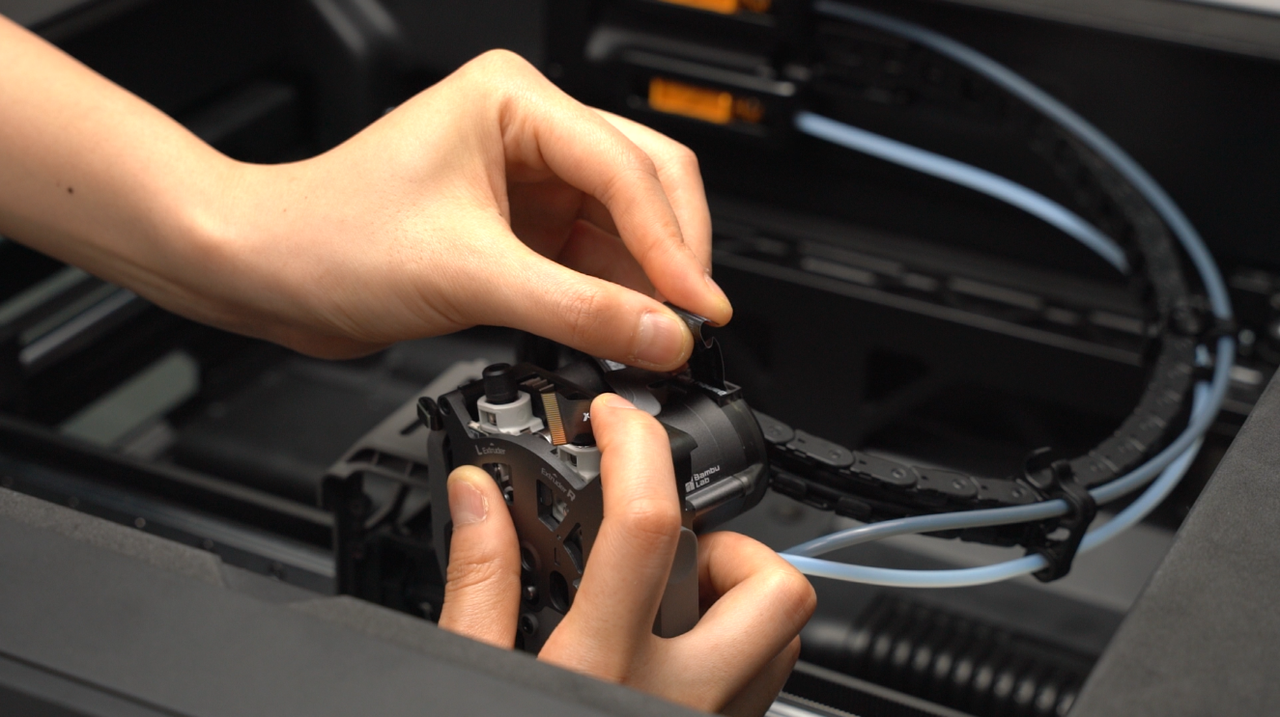
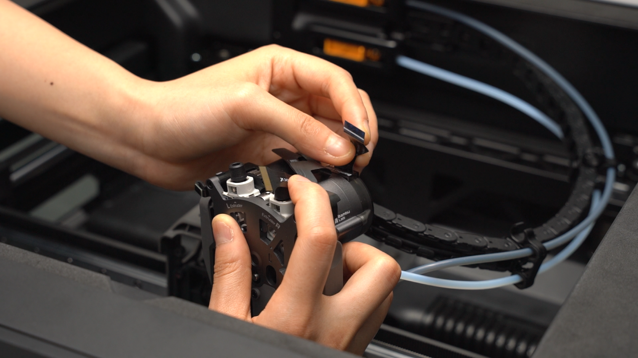
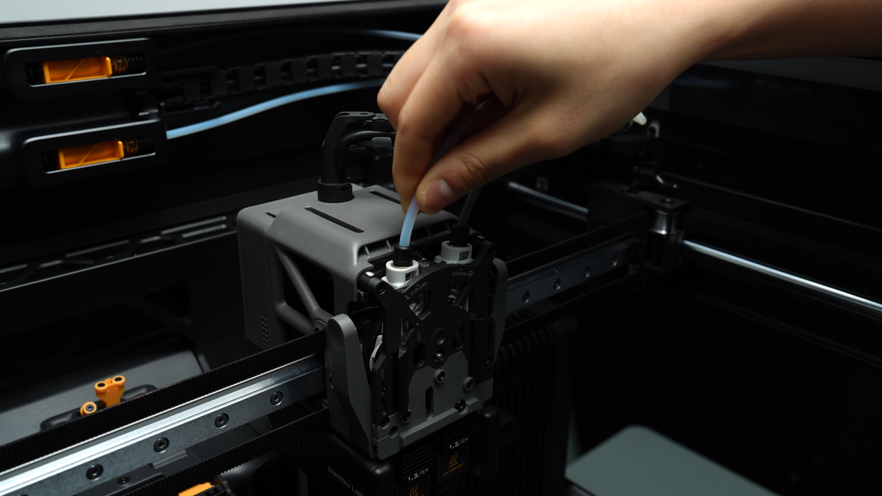
¶ Step 2:Remove the PTFE tube and the toolhead front cover
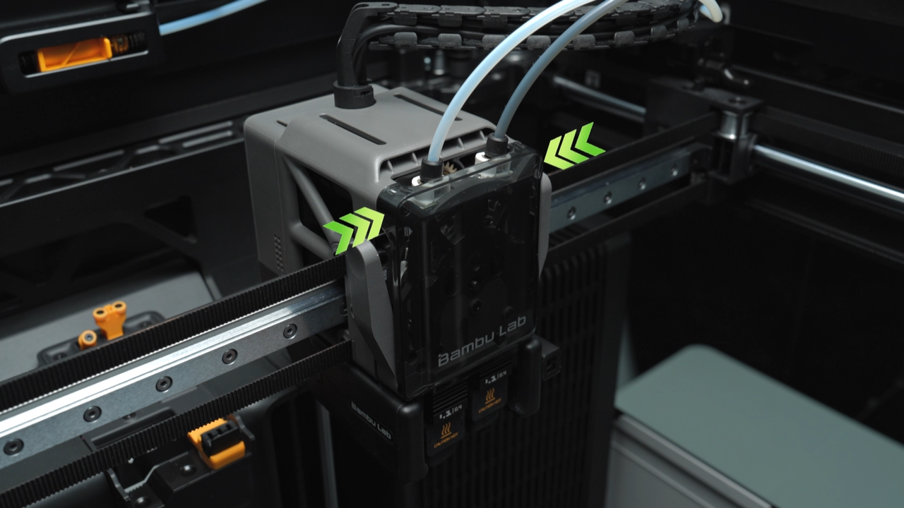
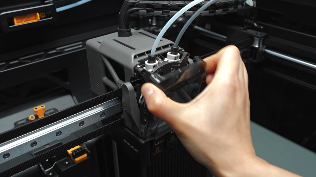
Pinch the top two corners of the toolhead front cover and lift upwards to remove the front cover.
In a symmetrical manner, press down on the black outer ring to unlock the two connectors on the extruder, releasing the PTFE tube.
 |
 |
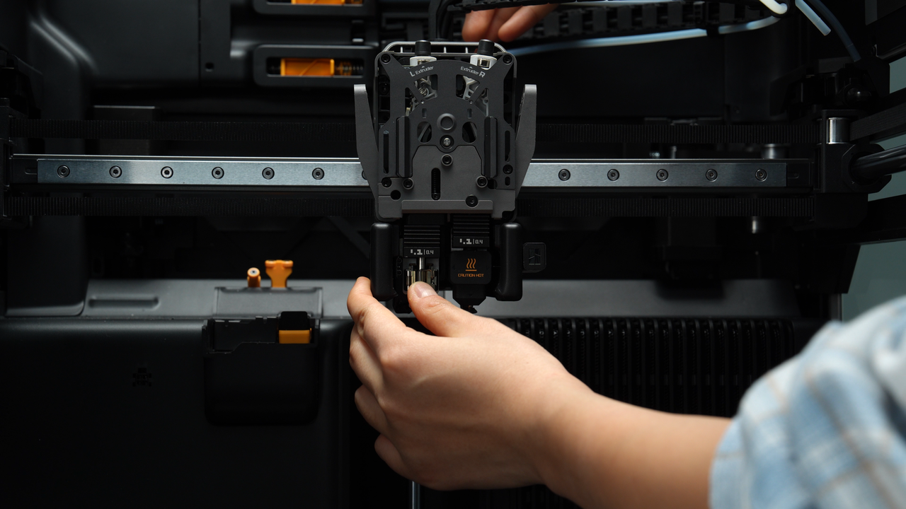
¶ Step 3:Remove the left and right hotends
The flow blocker is located on the lift connecting rod, and it moves left and right by toggling the connecting rod. If you need to remove a hotend but the flow blocker is blocking it, you must first move the flow blocker lever to clear the way before disassembling to prevent accidentally bending the flow blocker while removing the hotend. During toggling, the flow blocker may not fully move into position due to the tilt limit of the lever. In this case, a rough movement followed by fine adjustment is necessary to ensure the flow blocker is completely in place.
 |
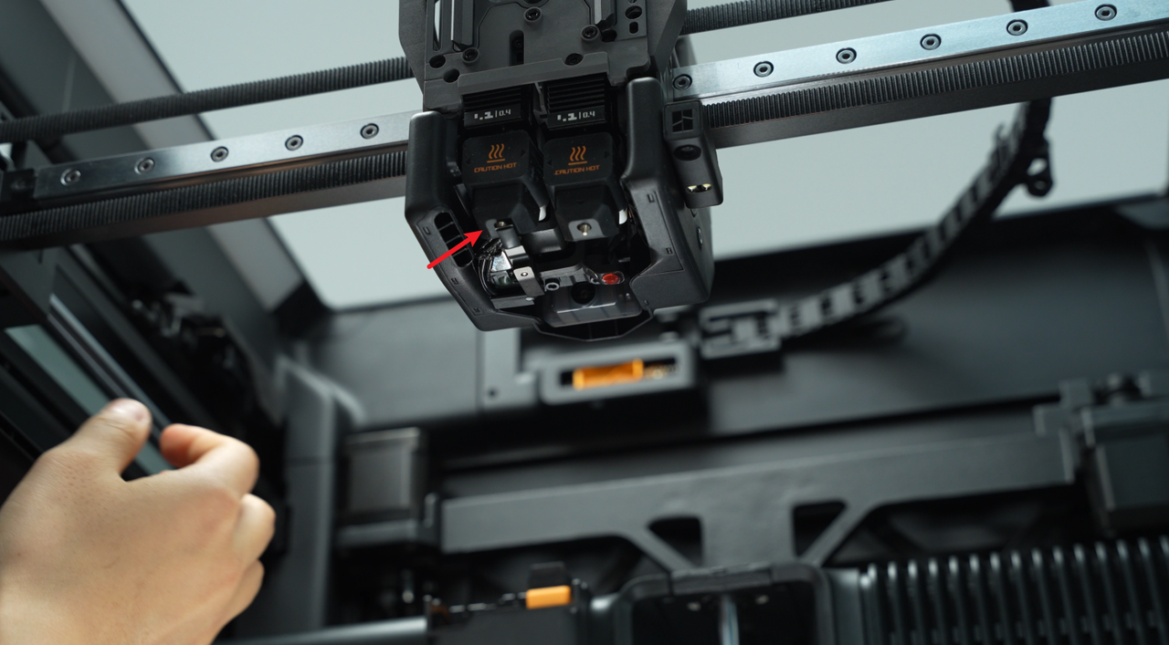 |
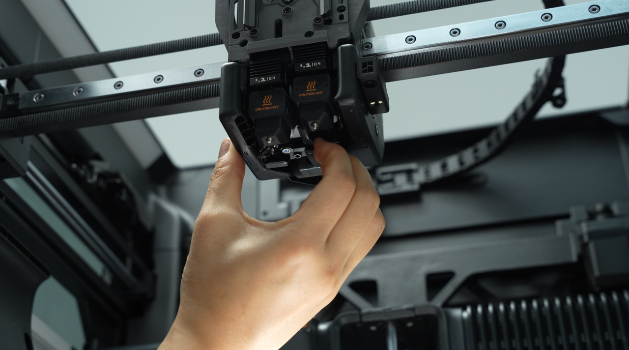
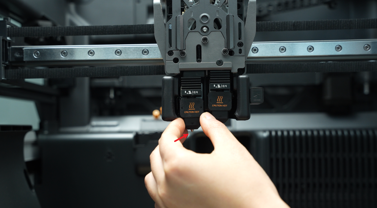
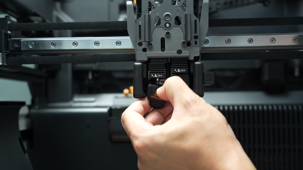
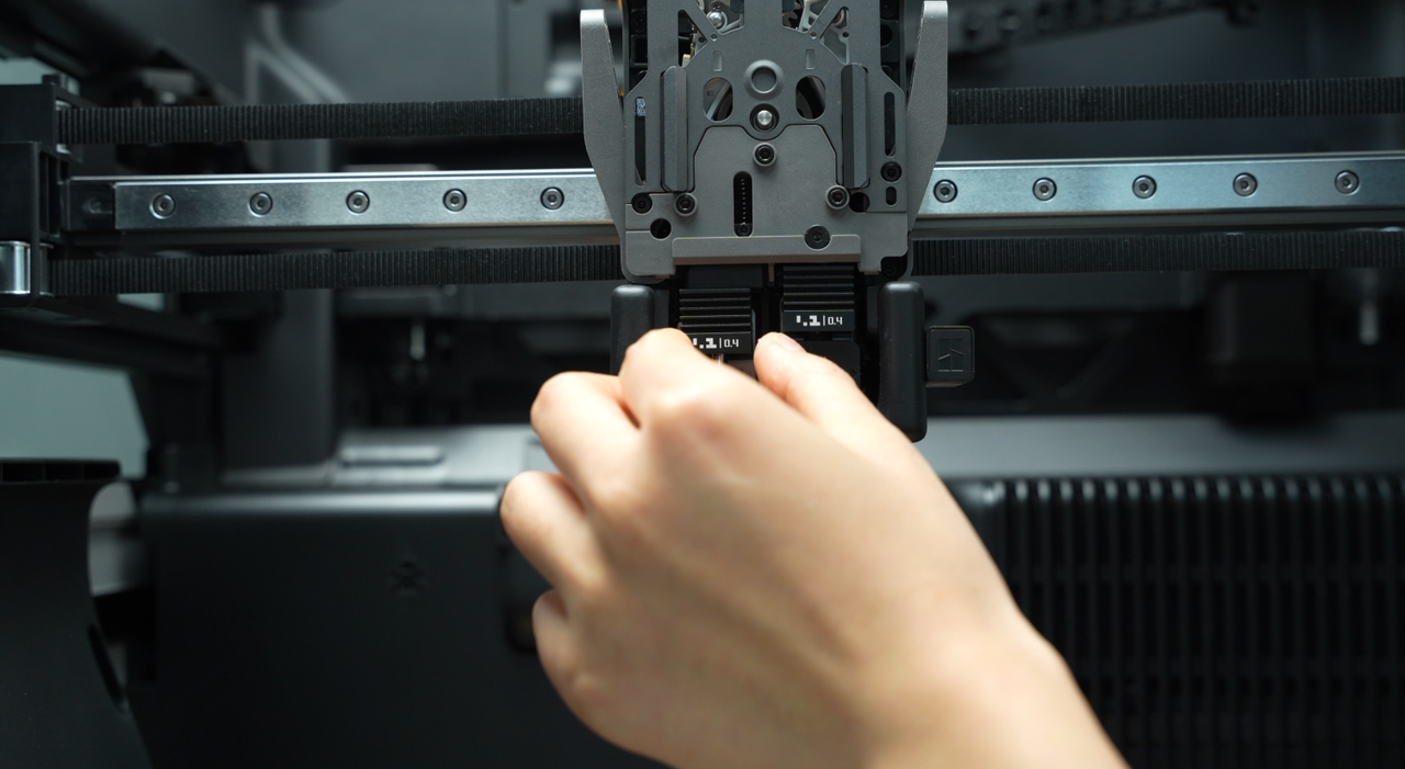
Before starting to remove the hotends, please press the cutters on both sides to cut the filament, making it easier to remove the hotends. Remove the silicone sock for hotend that is not blocked by the flow blocker, unlock the latch to remove the hotend, and pre-latch the latch of the heating assembly.
 |
 |
 |
 |
Toggle the flow blocker lever to move the flow blocker to the other side, remove the silicone sock of the remaining hotend, unlock the latch to remove the hotend, and pre-latch the latch of the heating assembly.
 |
 |
 |
 |
¶ Step 4:Remove the part cooling fan duct and fan
You can refer to this Wiki to remove the part cooling fan duct and fan, facilitating the subsequent removal of the extruder unit:
¶ Step 5:Remove the dual extruder unit
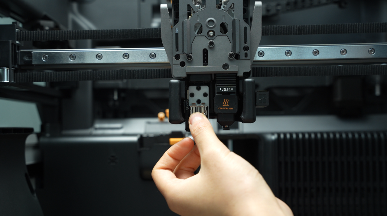
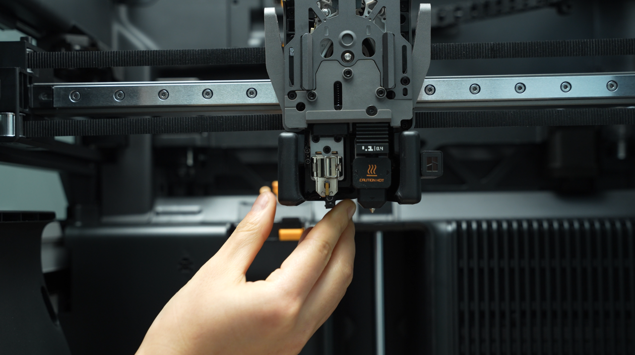
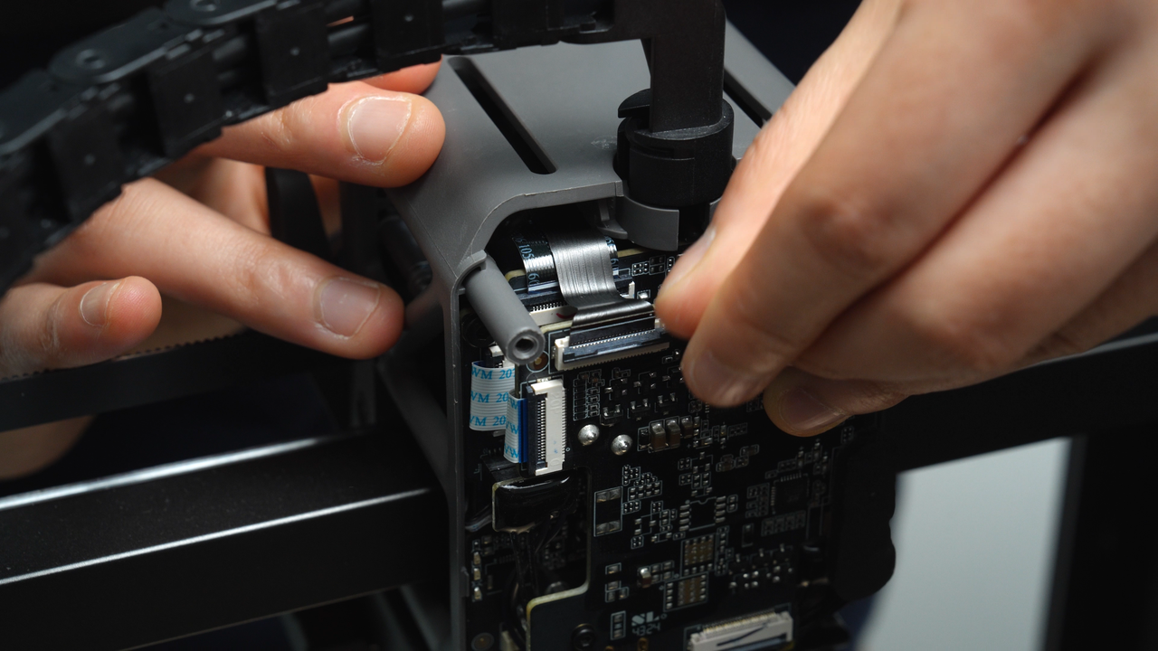
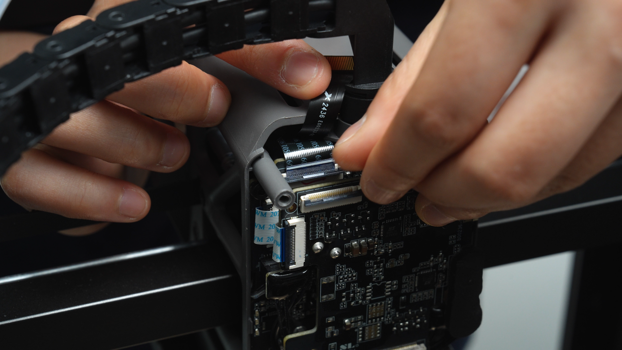
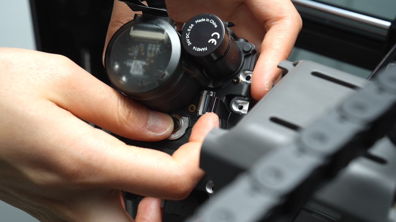
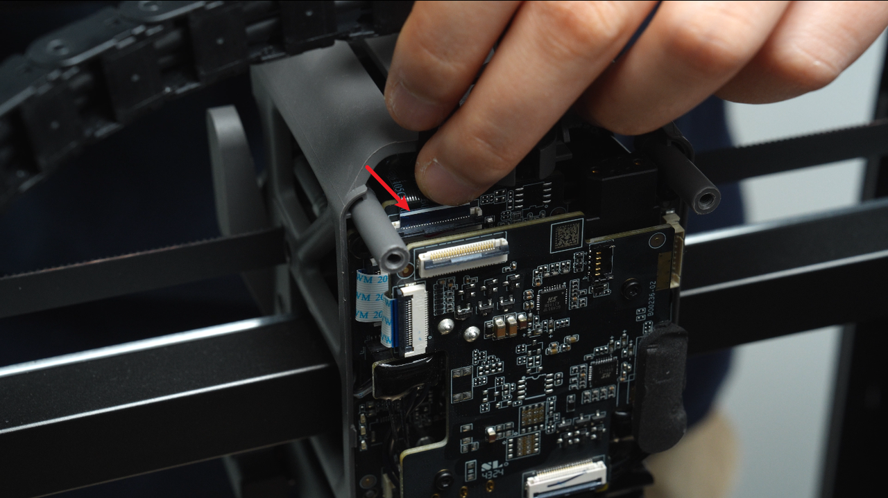
First, release the latch on the switching motor connection cable and disconnect it. Hold the switching motor connection cable with your fingers, then release the latch on the extrusion motor connection cable and disconnect it.
 |
 |
 |
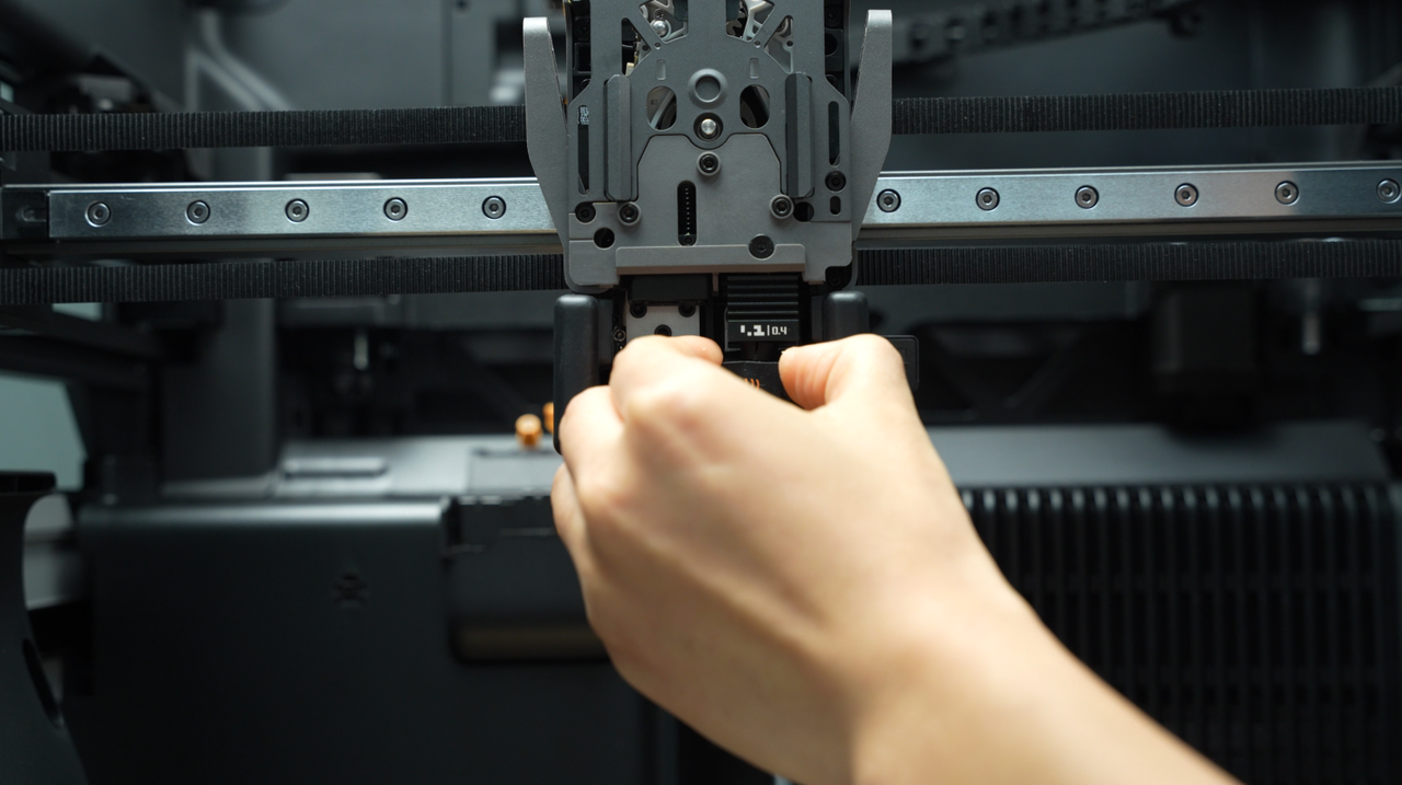
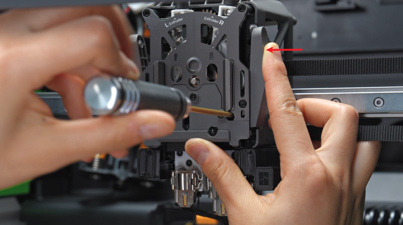
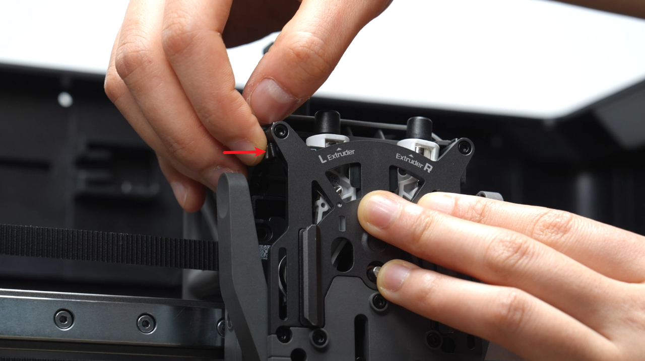
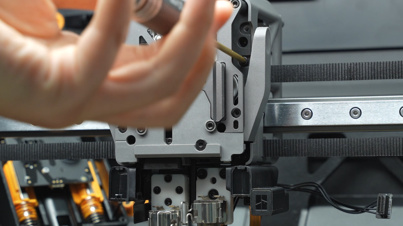
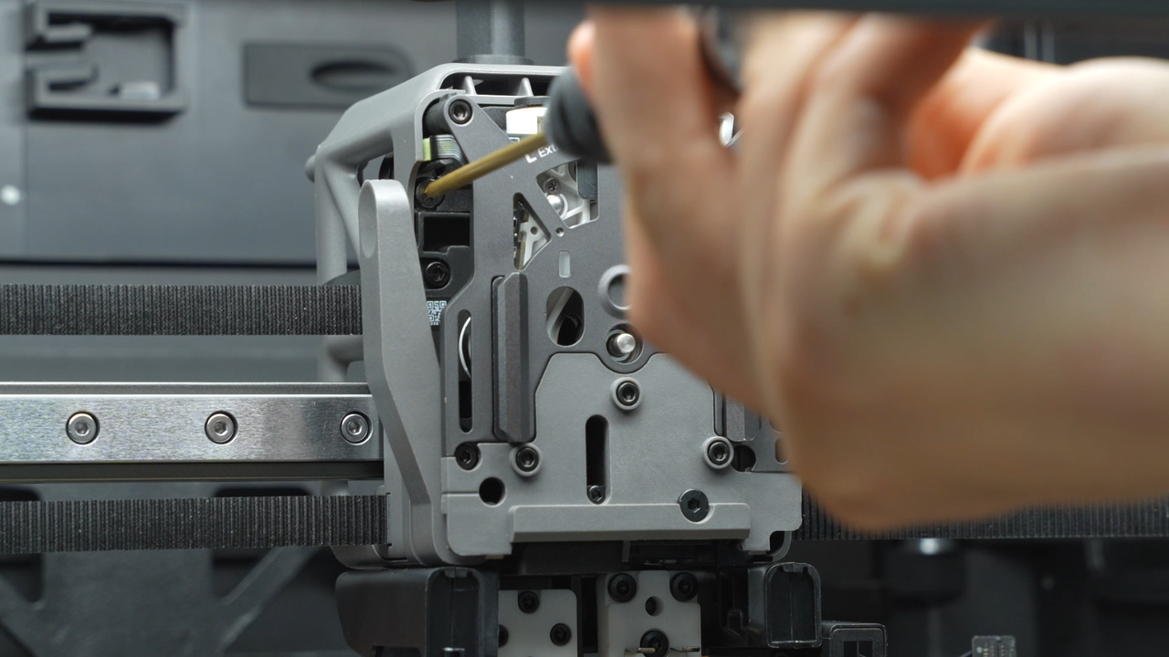
Use an H2.0 hex key to remove six fixing screws (the top two screws: BT2.6x8 * 2, and the remaining four screws: M2.5x8 * 2). When unscrewing the two screws at the bottom of the extruder filament guide, hold on the cutter first and then remove the screws.
As the two screws at the bottom of the extruder filament guide are located deep, loosening them completely may cause them to fall near the cutter and the extruder filament guide. If this situation occurs, gently shake the extruder to retrieve these screws after removing the extruder unit.
 |
 |
 |
 |
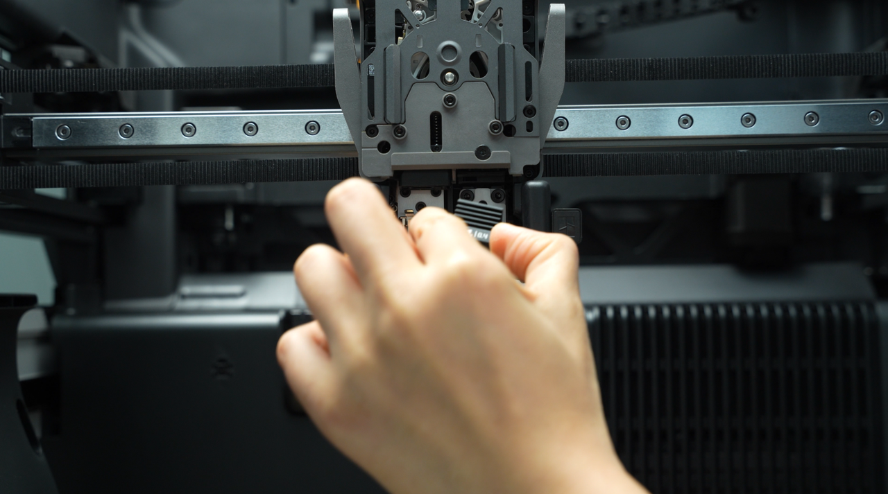
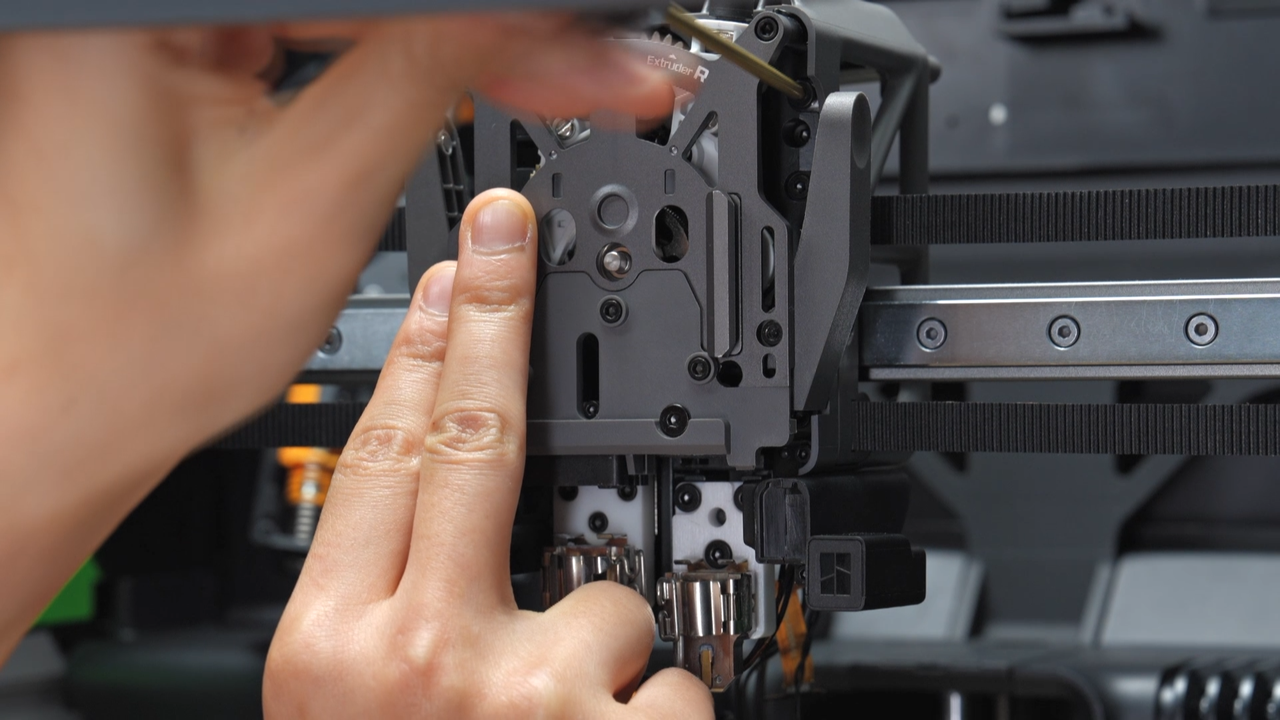
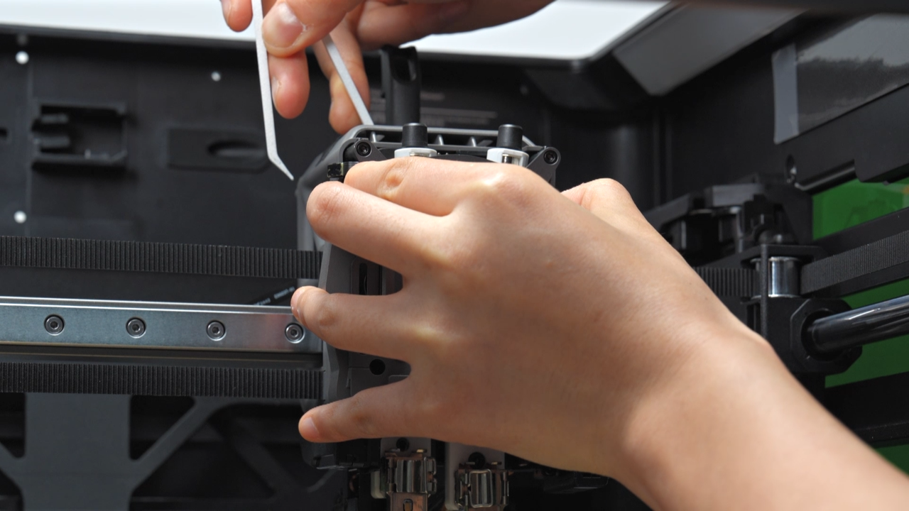
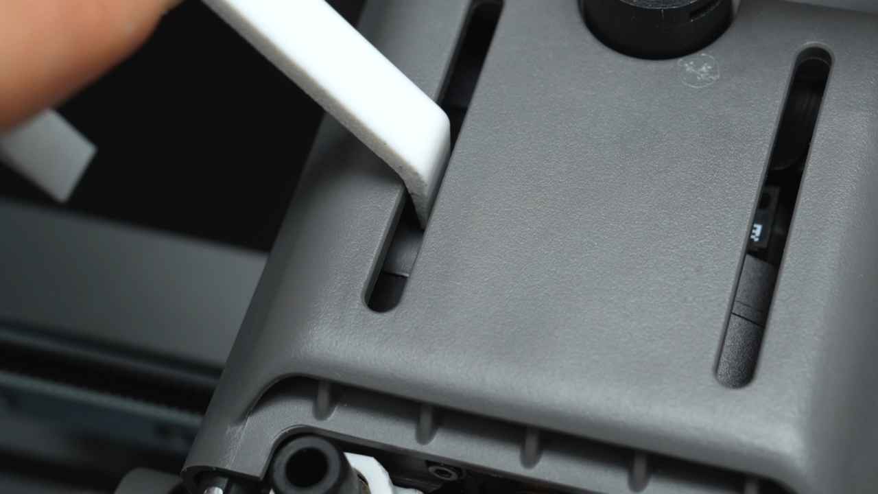
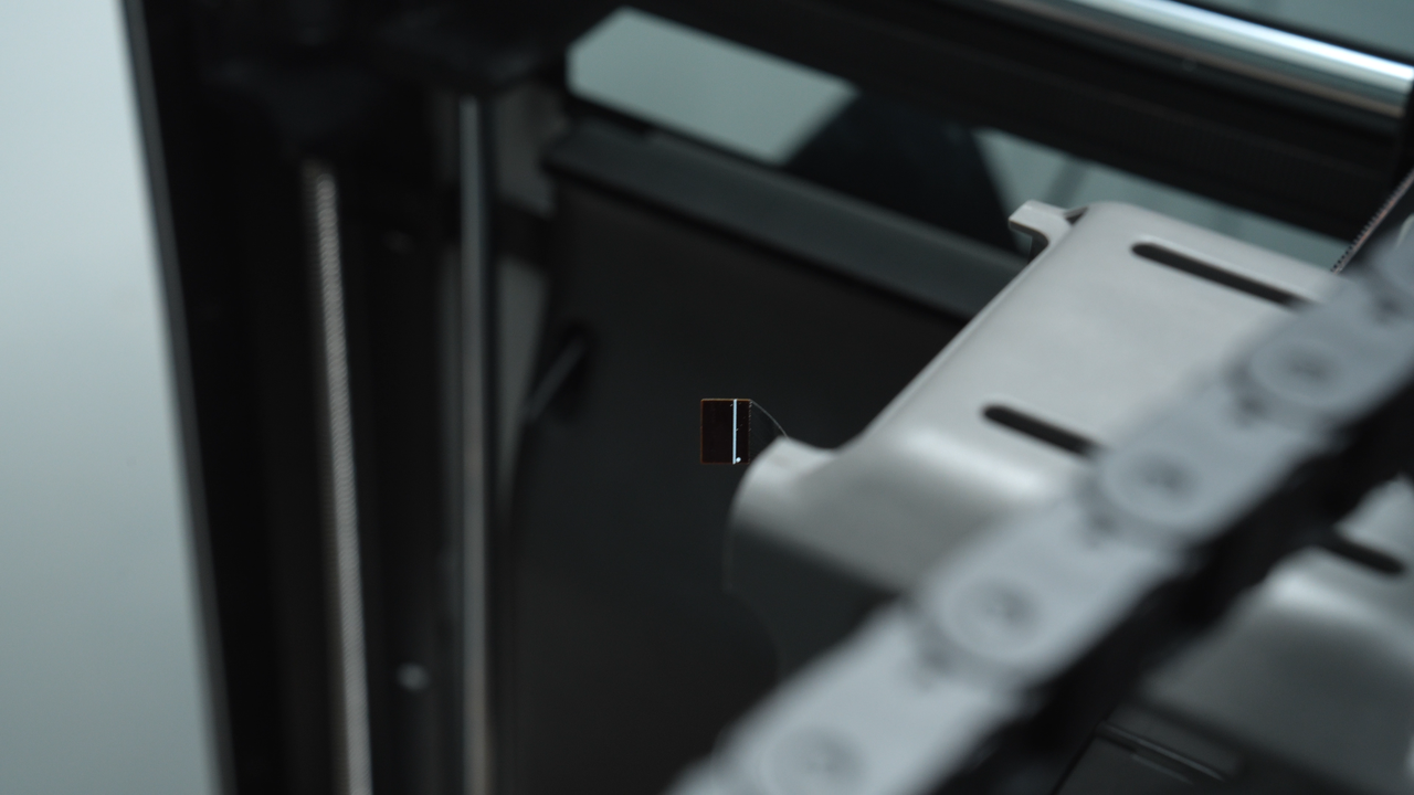
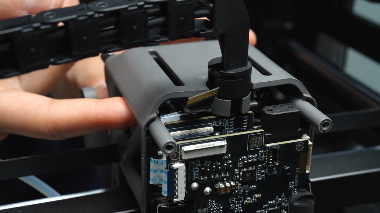
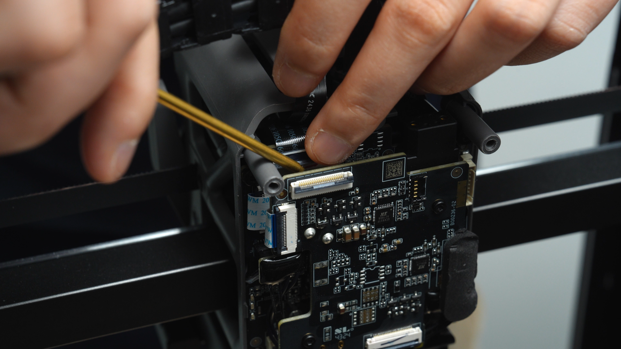
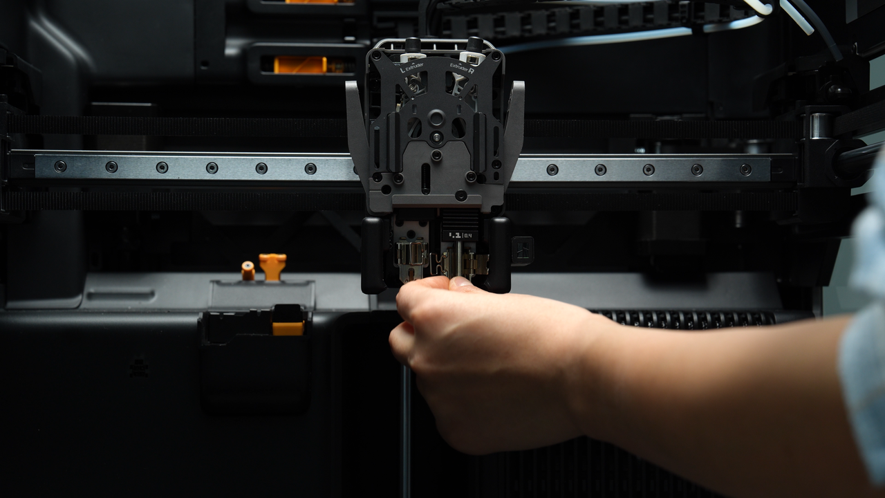
When removing the extruder unit, you can use a tweezer to flatten the internal cables from the gap above the tool head to prevent the cables from bending and hindering the removal of the extruder unit.
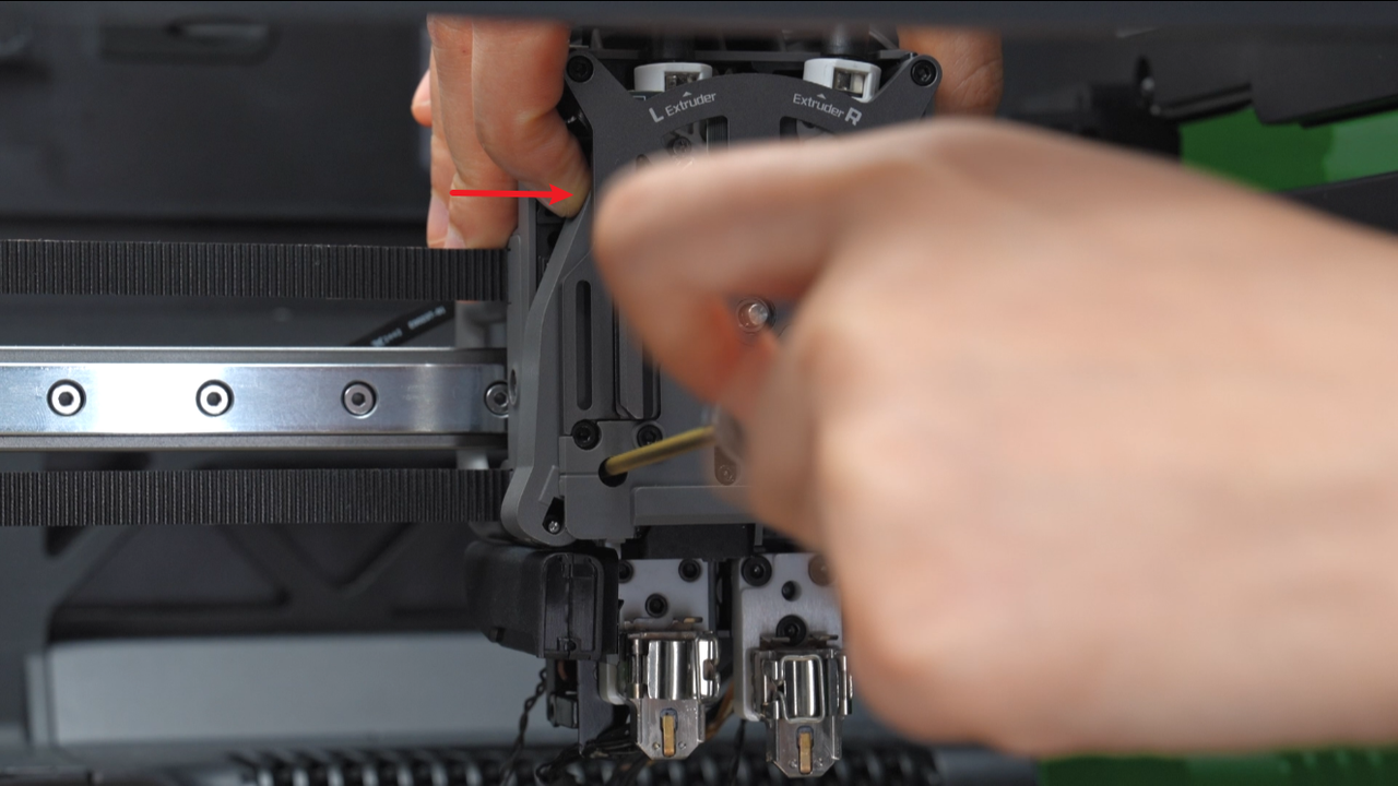
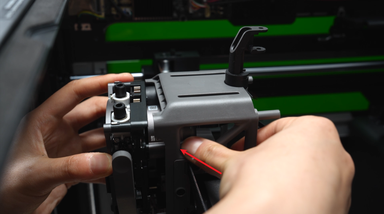
Then, flatten the cables at the back and push the extrusion motor cover outward with your fingers to remove the extruder at an inclined angle, avoiding interference between the extrusion motor cover and the middle frame.
 |
 |
 |
 |
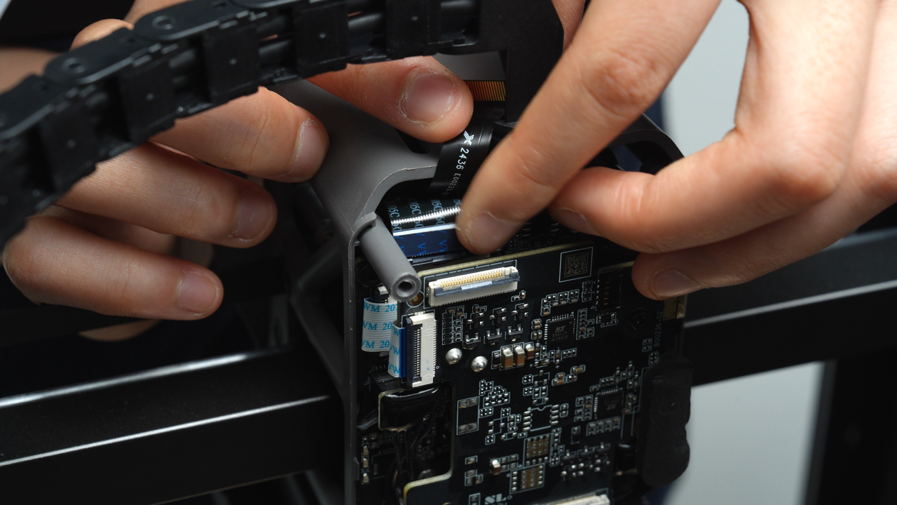
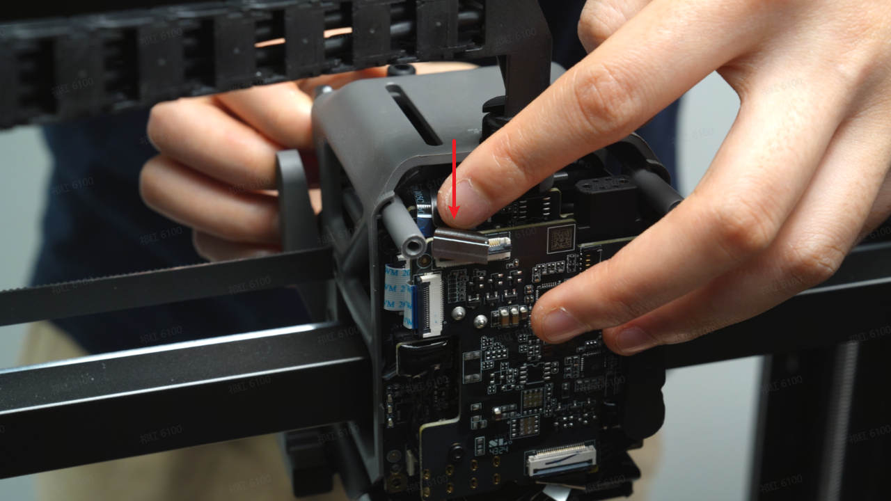
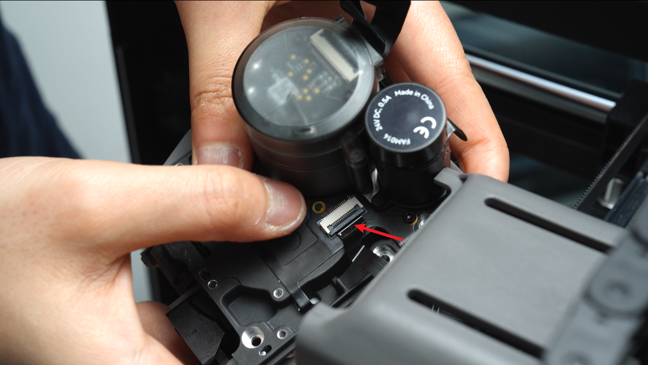
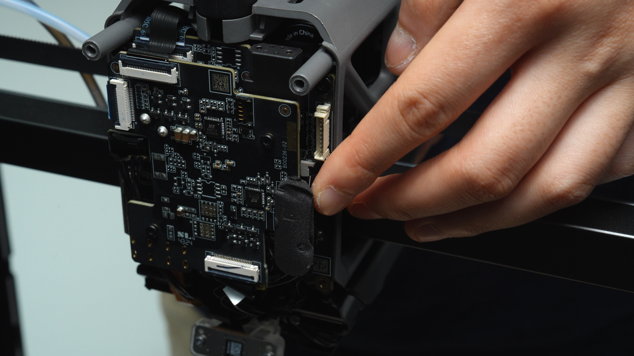
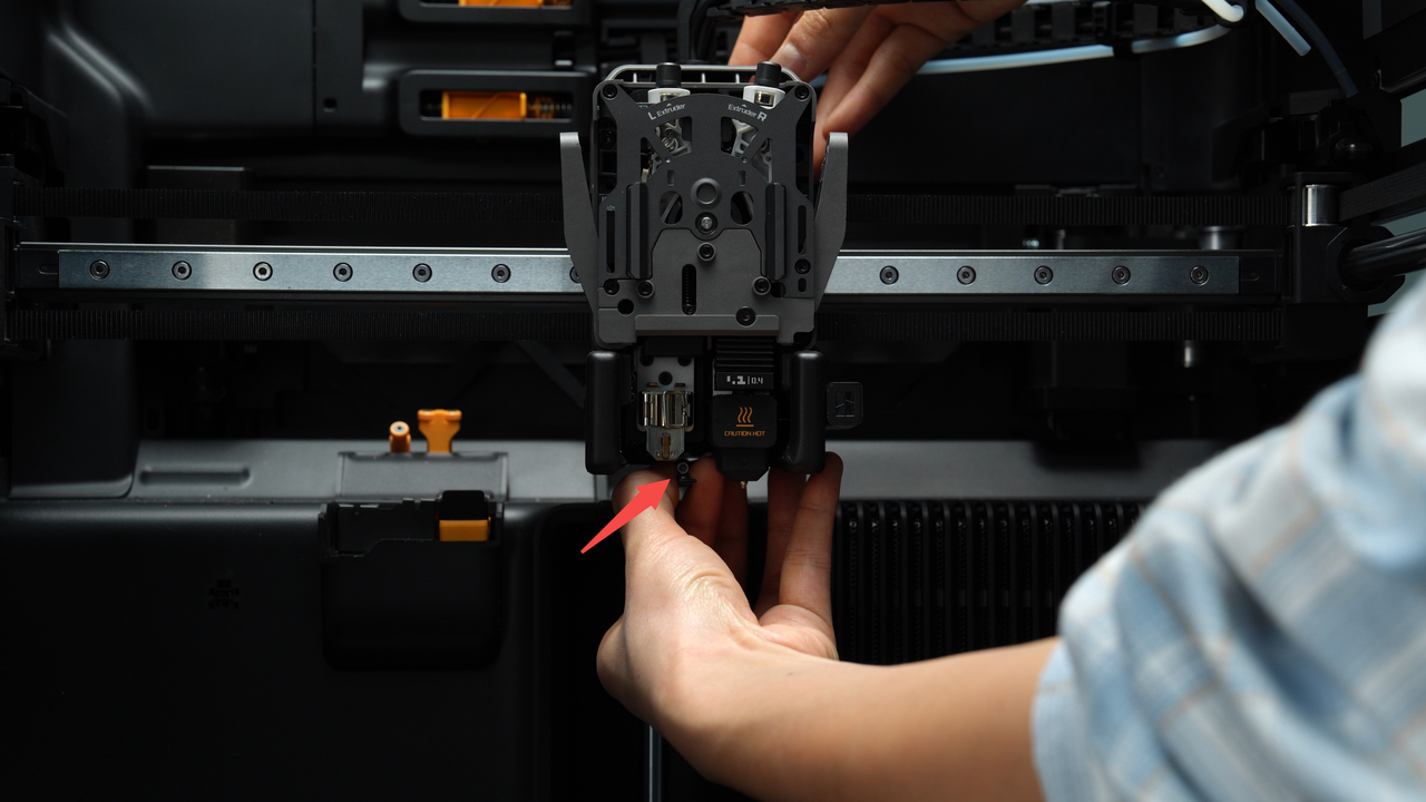
Release the latch on the toolhead sensor FPC cable, disconnect the toolhead sensor FPC cable, and remove the extruder unit.
 |
 |
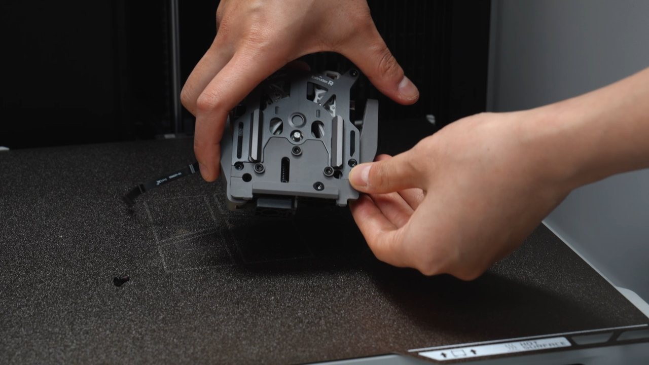
Gently shake the disassembled extruder unit above the heatbed to shake out any internal screws. Afterwards, organize and store all the screws properly to prevent loss.
¶ Assembly Guide
¶ Step 1:Install the dual extruder unit
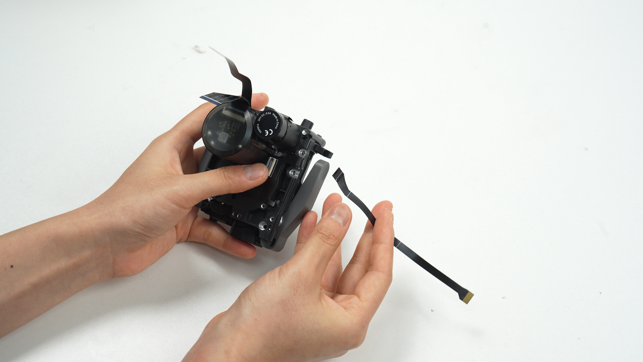
The extruder spare parts come with a toolhead sensor FPC cable. Release the latch and disconnect this new toolhead sensor FPC cable.
Before installing the new dual extruder unit, you need to adjust the angle of the switching motor cable and the extruder servo motor cable to allow them to pass smoothly through the toolhead middle frame.
Bend the head of the two cables slightly downward and the back half slightly upward, which will help the cables pass through the middle frame.
 |
 |
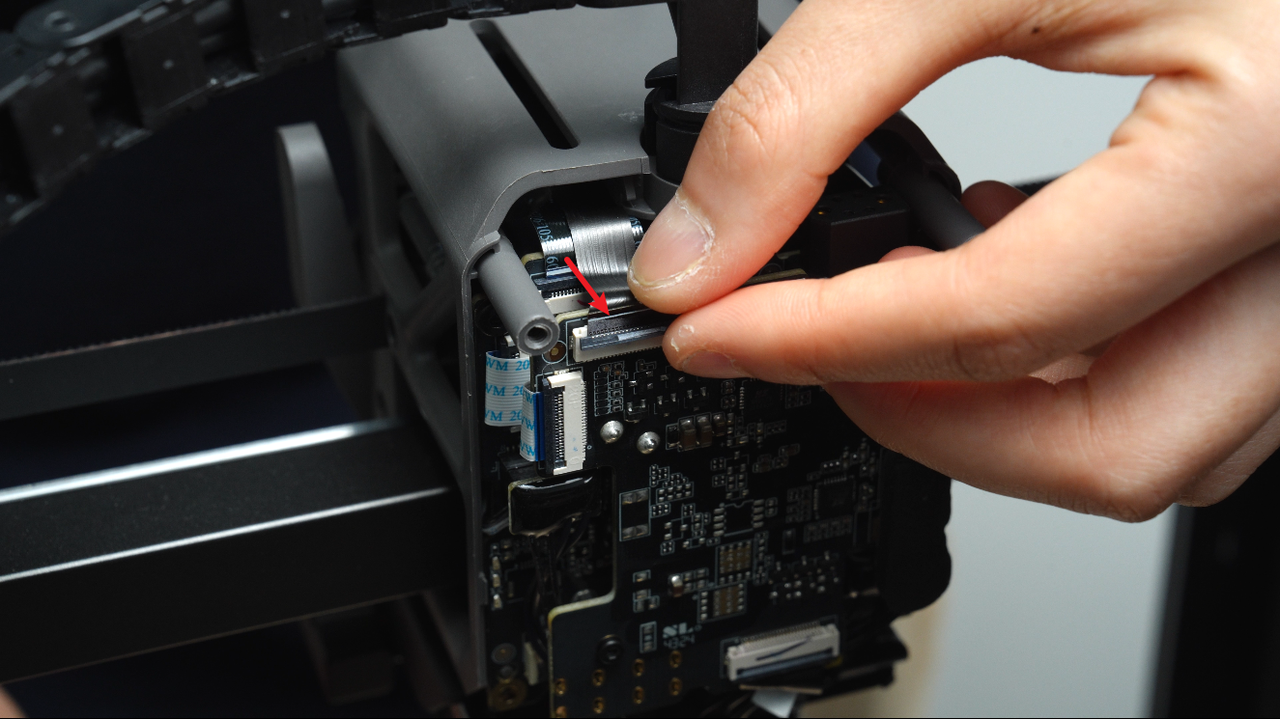
Next, we will start to formally install the new extruder assembly. First, insert the original extruder Hall connector into the socket, and make sure the white line on the connector is in a horizontal state, and then snap the socket in place.
When installing the dual extruder unit, you can use your fingers to push the connectors up from the side of the middle frame to help the connectors pass through the middle frame.
First, insert the extruder servo motor cable into the socket, make sure the white line on the cable is horizontal, and then snap the socket in place. If the clip on the extruder servo motor cable is difficult to snap in place, use an Allen key to help snap the socket in place; then insert the switching motor cable into the socket, make sure the white line on the cable is horizontal, and snap the socket in place.
 |
 |
 |
Insert the excess extruder Hall connector into the gap between the extruder connection board and the TH board; also insert the extruder Hall connector on the upper left side of the extruder into the gap of the toolhead.
 |
 |
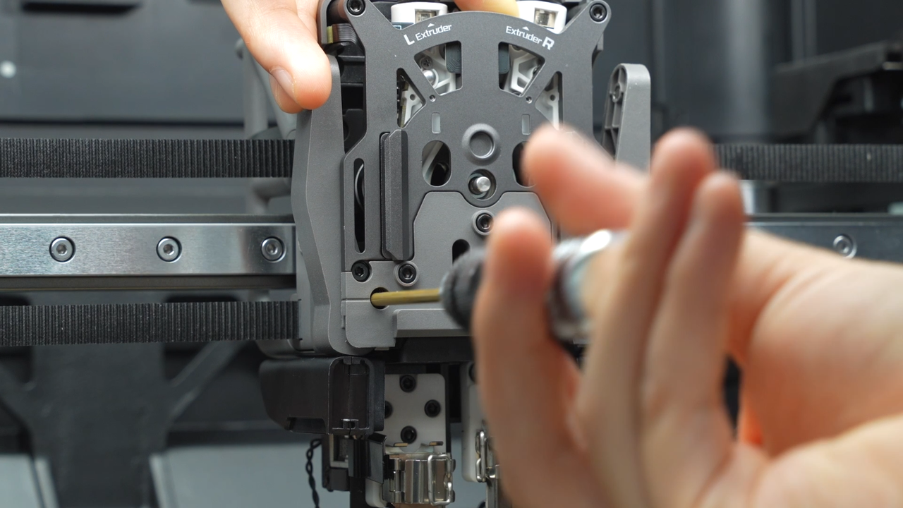
Use an H2.0 Allen key to tighten the six fixing screws (the top two screws: BT2.6x8 * 2, the remaining four screws: M2.5x8 * 2). When installing the two screws under the dual extruder filament guide, you can hold down the cutter and then screw in the screws.
 |
 |
 |
 |
¶ Step 2:Install the part cooling fan duct and fan
You can refer to this Wiki to install the part cooling fan duct and fan:
¶ Step 3:Install the left and right hotends
Same as disassembly steps, if you need to remove a hotend but the flow blocker is blocking it, you must first move the flow blocker lever to clear the way before disassembling to prevent accidentally bending the flow blocker while removing the hotend. During toggling, the flow blocker may not fully move into position due to the tilt limit of the lever. In this case, a rough movement followed by fine adjustment is necessary to ensure the flow blocker is completely in place.
Install the right hotend, tighten the nozzle latch, and install the silicone sock.
 |
 |
Toggle the flow blocker lever to move the flow blocker to the other side, install the left nozzle. Similarly, secure the nozzle latch and install the silicone sock.
Please note that when installing the silicone sock of the left hotend, ensure that the silicone sock cannot be tilted to avoid deformation of the wind blocker next to it.
 |
 |
 |
¶ Step 4:Install the PTFE tube and the toolhead front cover
Connect the two PTFE tubes, with the PTFE tube above the cable chain connecting to the right extruder and the PTFE tube below the cable chain connecting to the left extruder.
When reinstalling the front cover of the toolhead, first position it under the extruder and then push it back to secure the front cover in place.
¶ Verify the Functionality
Connect the power supply and turn on the printer, initiate printing, and confirm whether it can print successfully.
¶ End Notes
We hope the detailed guide provided has been helpful and informative.
If this guide does not solve your problem, please submit a technical ticket, we will answer your questions and provide assistance.
If you have any suggestions or feedback on this Wiki, please leave a message in the comment area. Thank you for your support and attention!