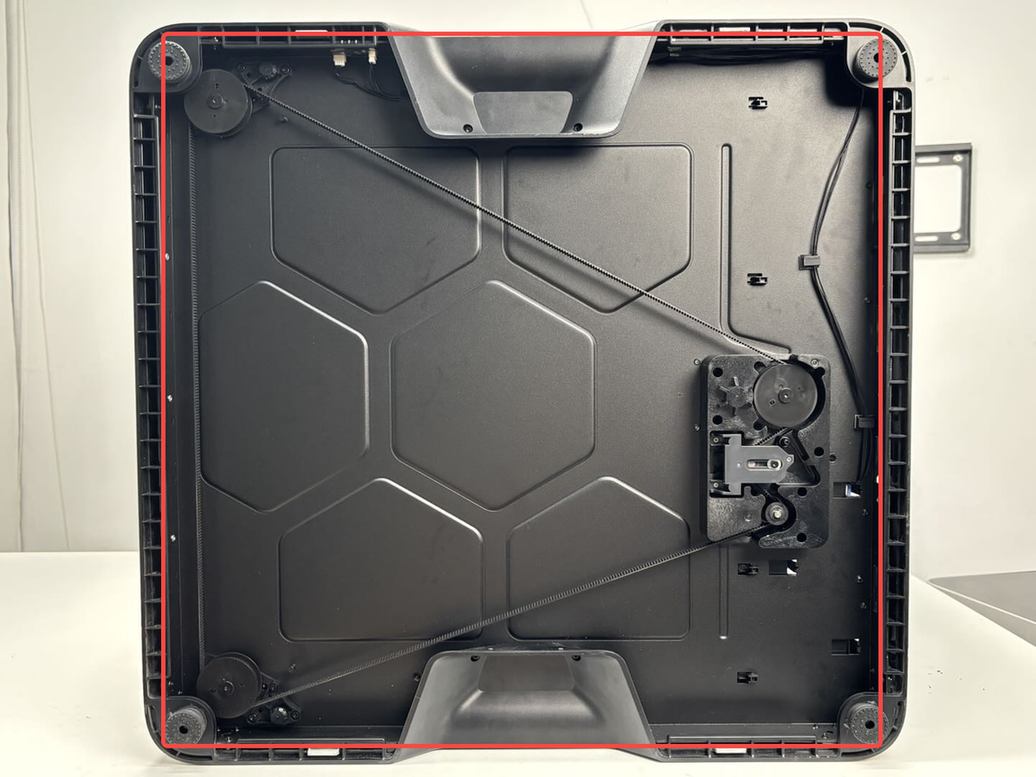
¶ Enclosure Plastic Bottom Ring
The enclosure plastic bottom ring is secured to the printer's base with screws, and the printer's 4 feet are installed on the bottom.
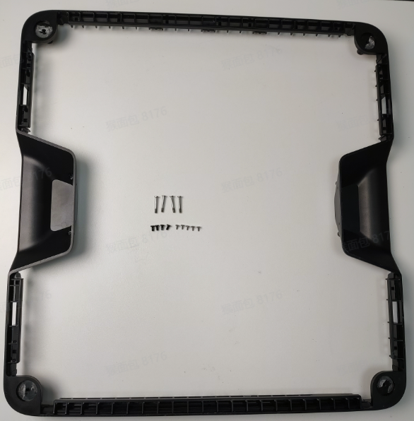
The spare parts for the enclosure plastic bottom ring include the following:
-
Enclosure plastic bottom ring (pre-installed feet) * 1
-
M3x6 screws - for fixing the enclosure plastic bottom ring handle * 4
-
BT2x5 screws - for fixing the inner side of the enclosure plastic bottom ring * 6
-
M3x21.5x6 screws - for fixing the printer * 4
-
M3-3.2-10-0.5 washers * 4
¶ When to use
- When the enclosure plastic bottom ring is damaged.
¶ Tools and materials needed
-
New enclosure plastic bottom ring
-
H2.0 Allen key
-
An L-shaped H2.0 Allen key (the shorter side is recommended to be less than 38mm)
-
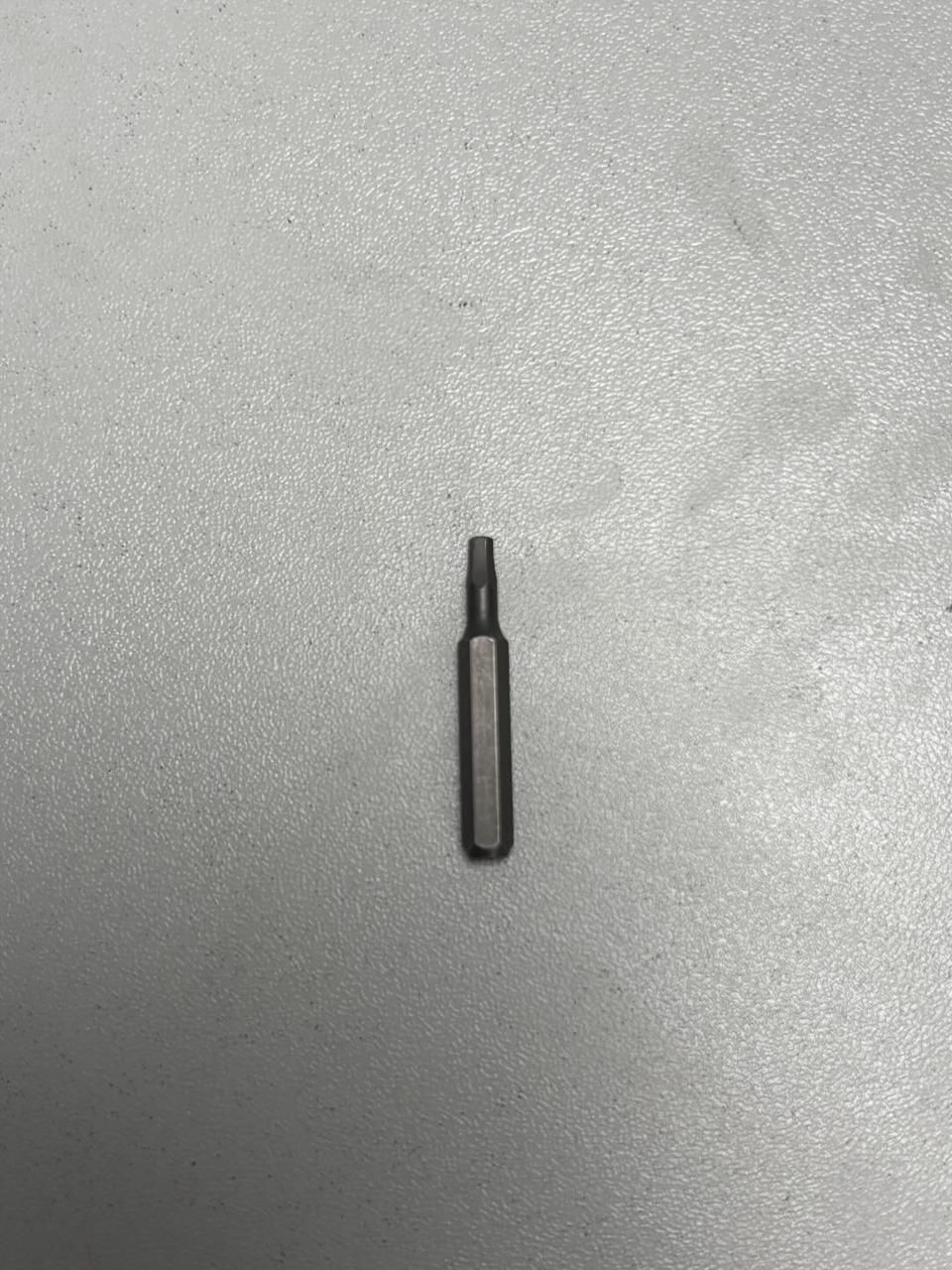
If possible, prepare a shorter bit (recommended to be less than 38mm) for easier disassembly and assembly.
The screw specifications and models involved in the disassembly and assembly process:
-
M3x6 screws - for fixing the enclosure plastic bottom ring handle * 4
-
M2x5 screws - for fixing the side of the enclosure plastic bottom ring * 6
-
M3x21.5x6 screws - for fixing the feet and the enclosure plastic bottom ring * 4
¶ Safety Warning
IMPORTANT!
It's crucial to power off the printer before conducting any maintenance work, including work on the printer's electronics and tool head wires. Performing tasks with the printer on can result in a short circuit, leading to electronic damage and safety hazards.
During maintenance or troubleshooting, you may need to disassemble parts, including the hotend. This exposes wires and electrical components that could short circuit if they contact each other, other metal, or electronic components while the printer is still on. This can result in damage to the printer's electronics and additional issues.
Therefore, it's crucial to turn off the printer and disconnect it from the power source before conducting any maintenance. This prevents short circuits or damage to the printer's electronics, ensuring safe and effective maintenance. For any concerns or questions about following this guide, we recommend submitting a technical ticket regarding your issue and we will do our best to respond promptly and provide the assistance you need.
¶ Remove the enclosure plastic bottom ring
¶ Step 1: Lay down the printer
Lay the printer down and place it steadily on the table.
Given the printer's weight, it is recommended that two people work together to avoid potential damage.
¶ Step 2: Remove the screws
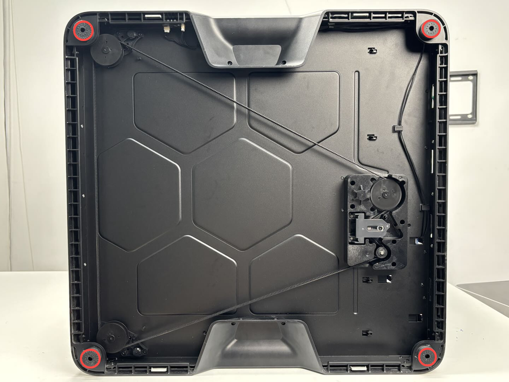
- Use the H2.0 Allen key to remove the 4 screws at the handle (marked with red squares, M3x6), then use the L-shaped H2.0 Allen key to remove the 6 screws on the side (marked with green circles, BT2x5).
Note: Two BT2x5 screws are blocked by the Z-axis tensioner. Use the shorter side of the L-shaped Allen key to loosen them. If a shorter H2.0 bit is available, use it to remove the screws after loosening them with the L-shaped Allen key.
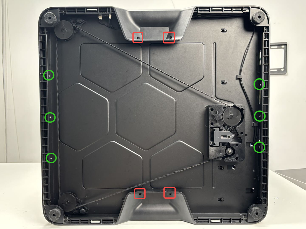
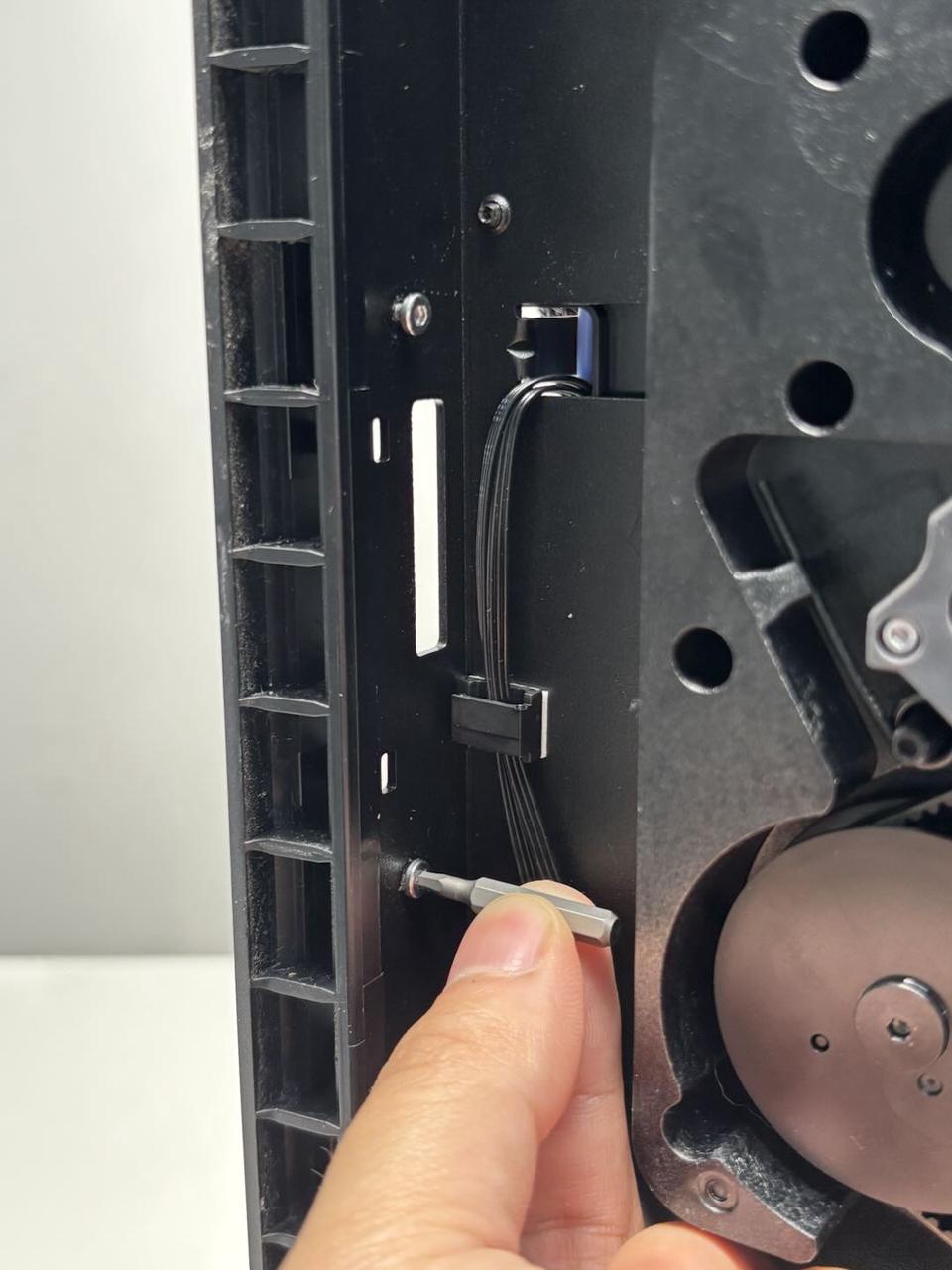
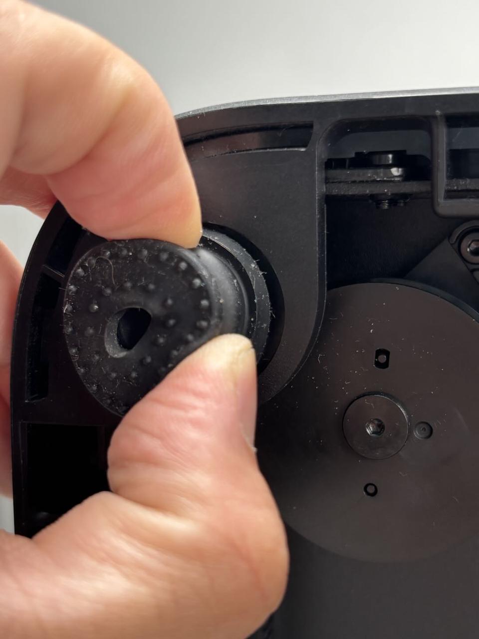
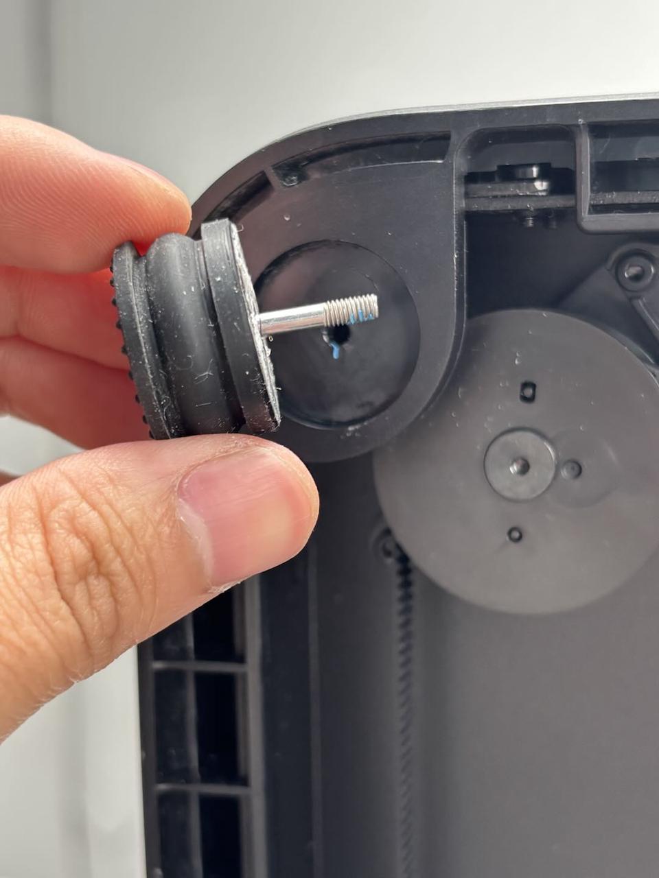
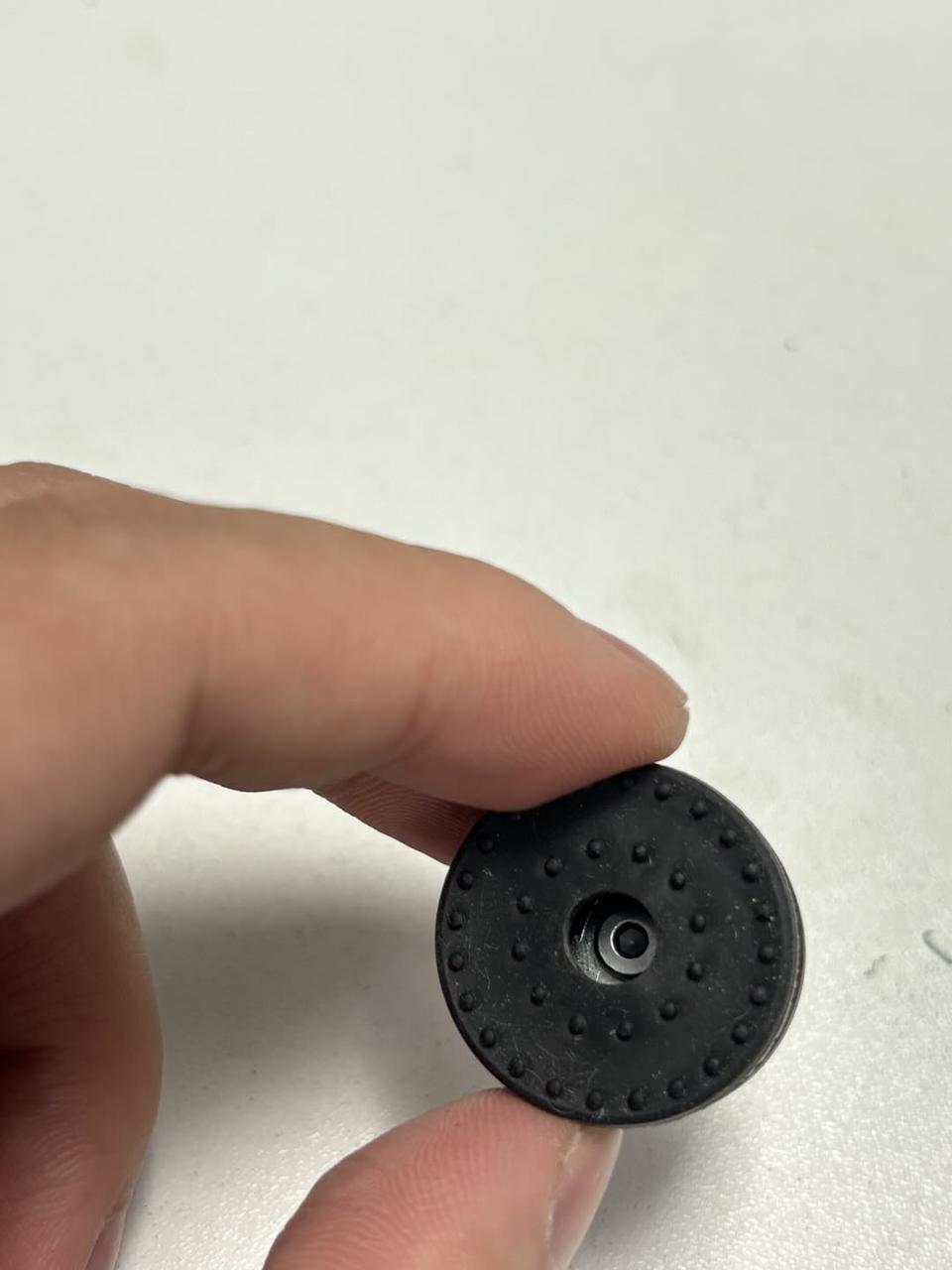
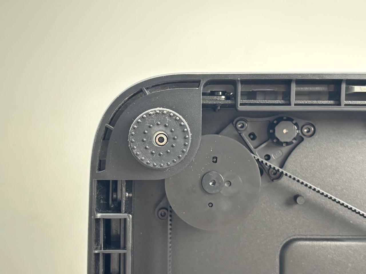
- Use the H2.0 Allen key to remove the 4 screws (M3x21.5x6) securing the printer feet. Detach the feet, screws, and washers together.
The feet are also attached to the ring with adhesive. After removing the screws, peel off the feet.

¶ Step 3: Remove the enclosure plastic bottom ring
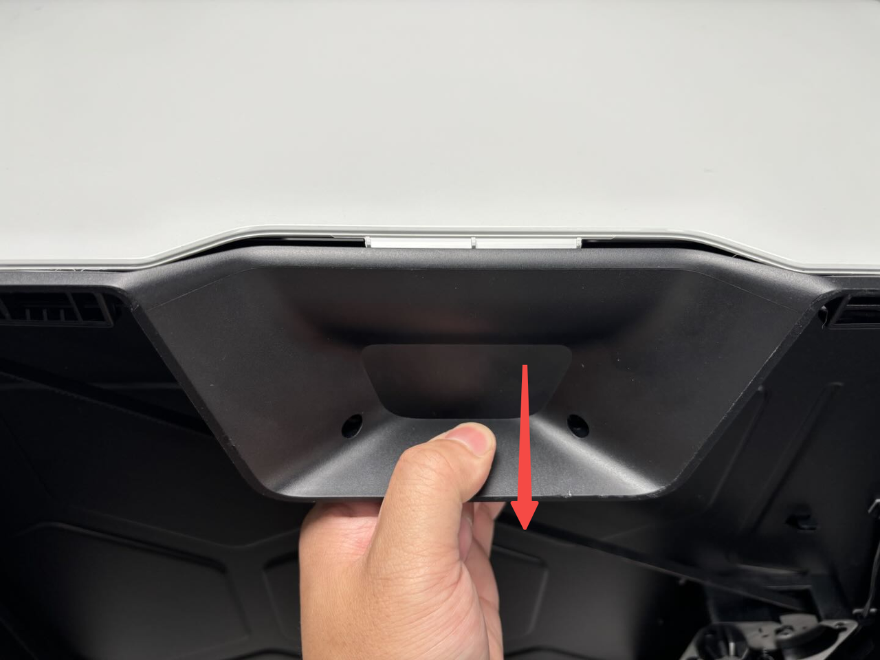
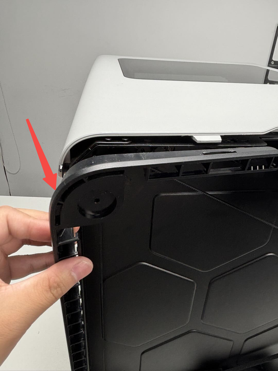
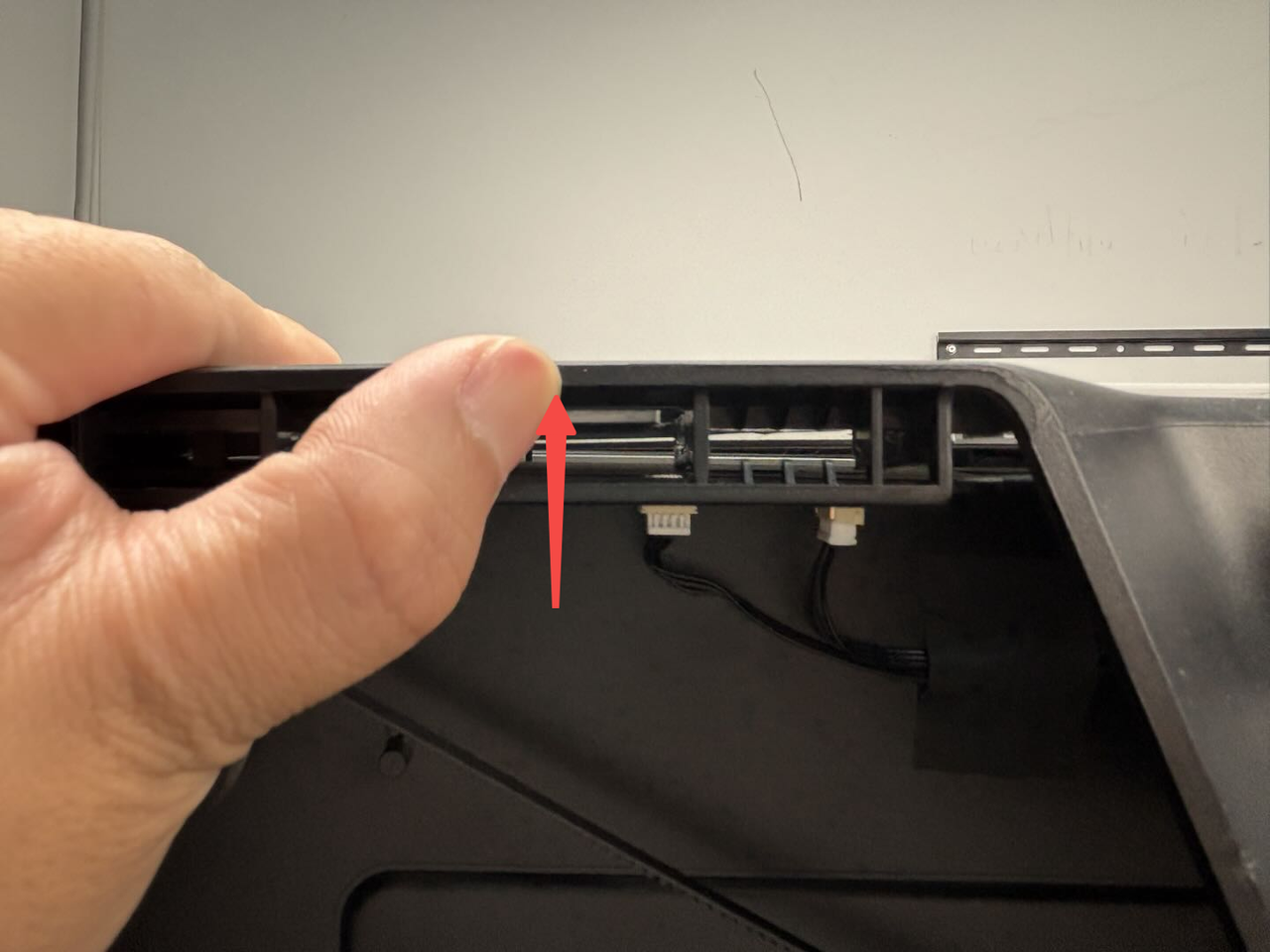
- First, pull the handle of the bottom ring to partially pull the ring out of the printer.
- Then, pull the left and right feet to completely pull out that side of the ring from the printer.
- For the handle on the other side, you can flip the printer over so that this side is on top for easier removal. Alternatively, you can slide the printer out slightly so that the ring is suspended, and then follow the above steps "1,2" to pull the bottom ring out of the printer.
Note:
If the printer is suspended, ensure the table is stable and avoid excessive suspension to prevent the printer from falling.
Since the side panels are not anti-slip, hold the printer with your hands while pulling the bottom ring to avoid it falling.

¶ Install the enclosure plastic bottom ring
¶ Step 1: Reinstall the enclosure plastic bottom ring
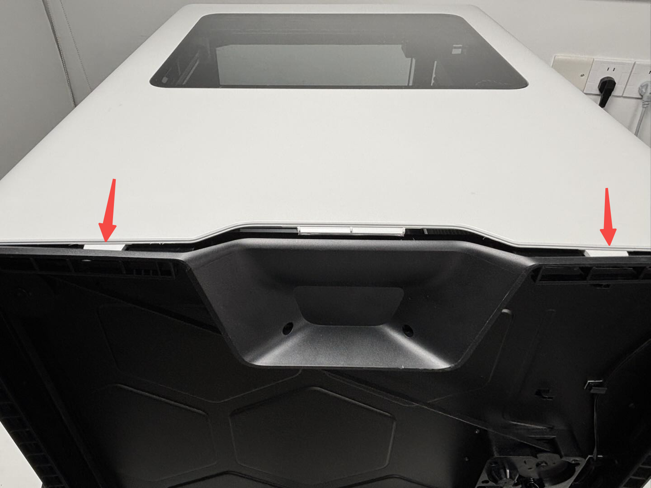
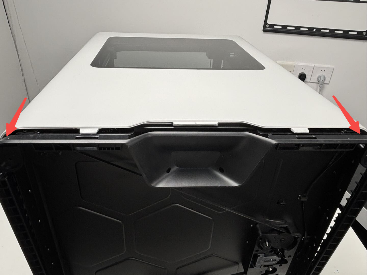
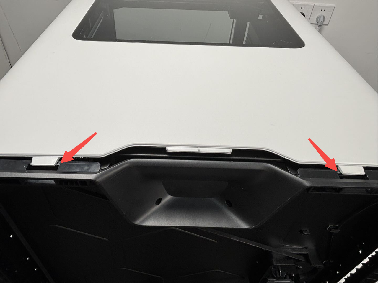
- Align the handle position of the new enclosure plastic bottom ring with the two side panels of the printer. Insert the two clips on the side panels into the ring first. While pushing the ring, you can use your hands to push the edge of the ring upward to ensure the clips are inserted.
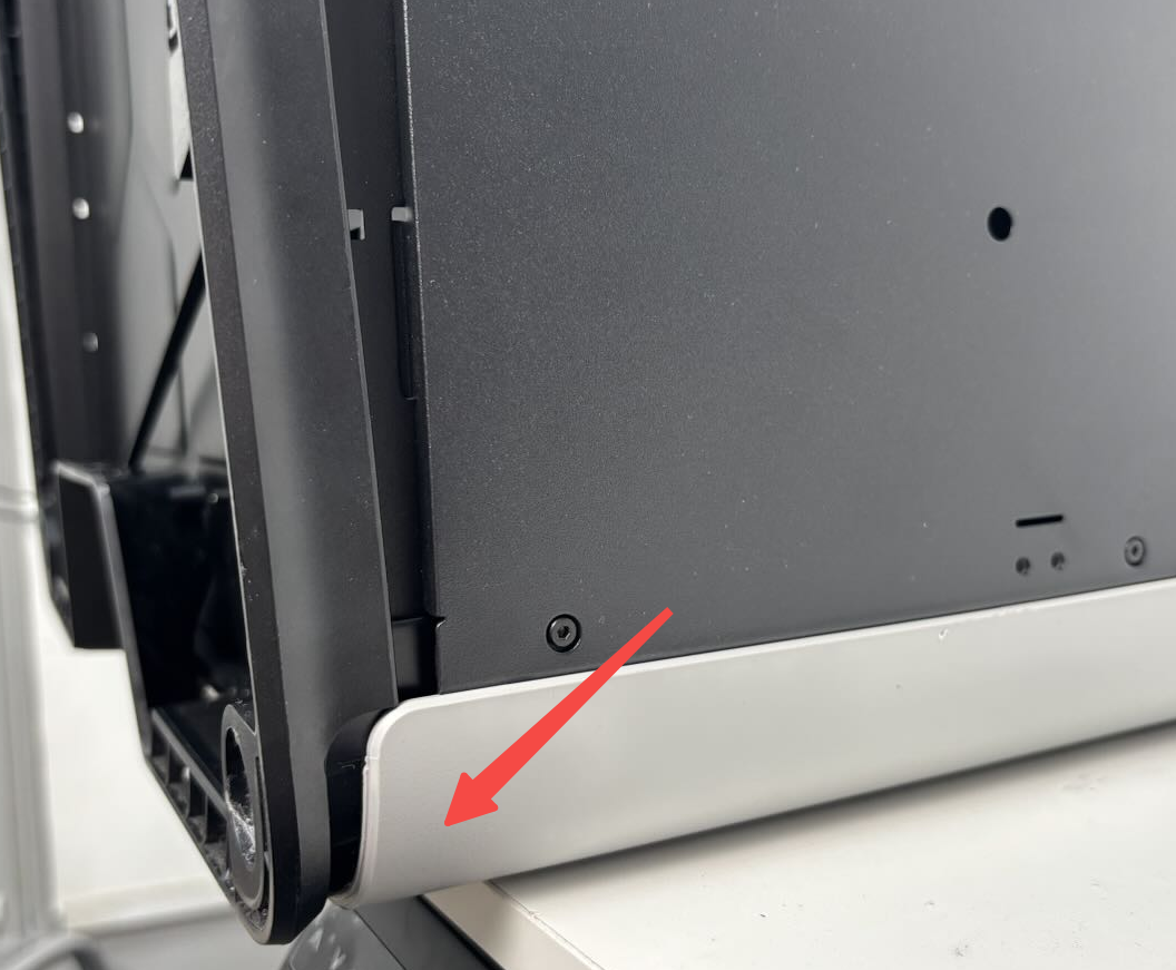
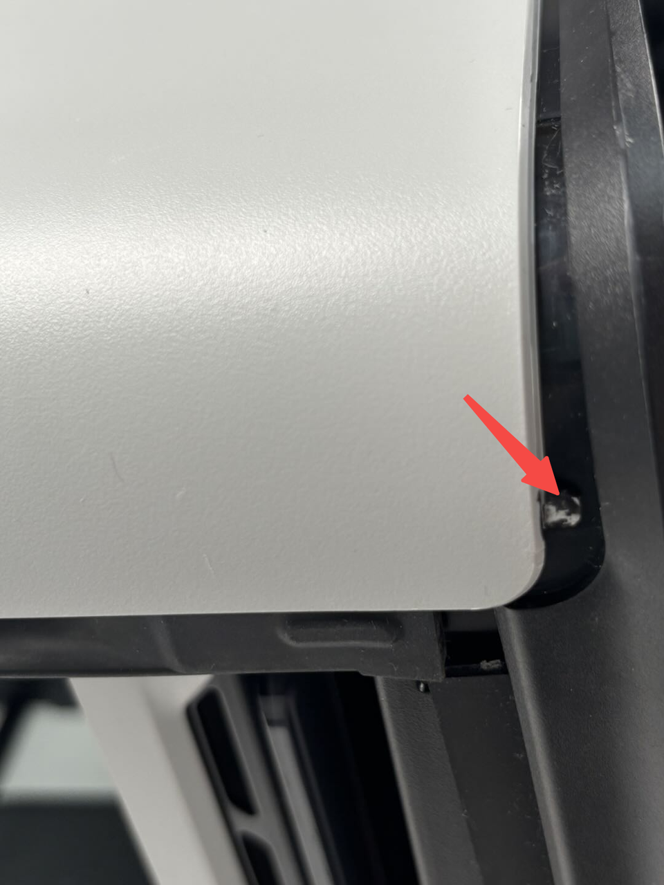
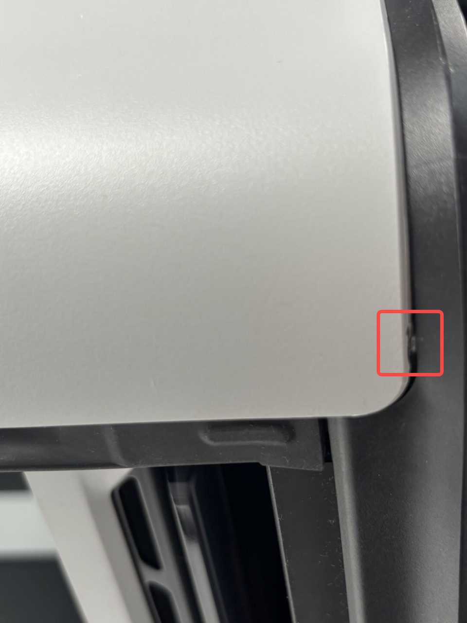
- Push the ring inward while paying attention to a small clip at the front door. Ensure this clip snaps into the bottom ring, then fully push the ring into place on this side.
- Flip the printer over and follow the above steps "1,2" to fully snap the bottom ring into the printer on the other side (ensure all clips are inserted; you can gently tap the bottom ring to fully secure it). Check if the bottom ring is properly installed. If any clips are exposed or raised, remove the raised part and reinstall it.
For detailed information on the clips at the bottom of the left and right side panels, refer to these Wiki articles:
Replace H2D Left/Right Side Panel
¶ Step 2: Tighten the screws
- Thread the washers onto the screws (M3x21.5x6), then insert the screws and washers into the feet. Pull the bottom of the screws by hand to secure the washers and screws into the feet.
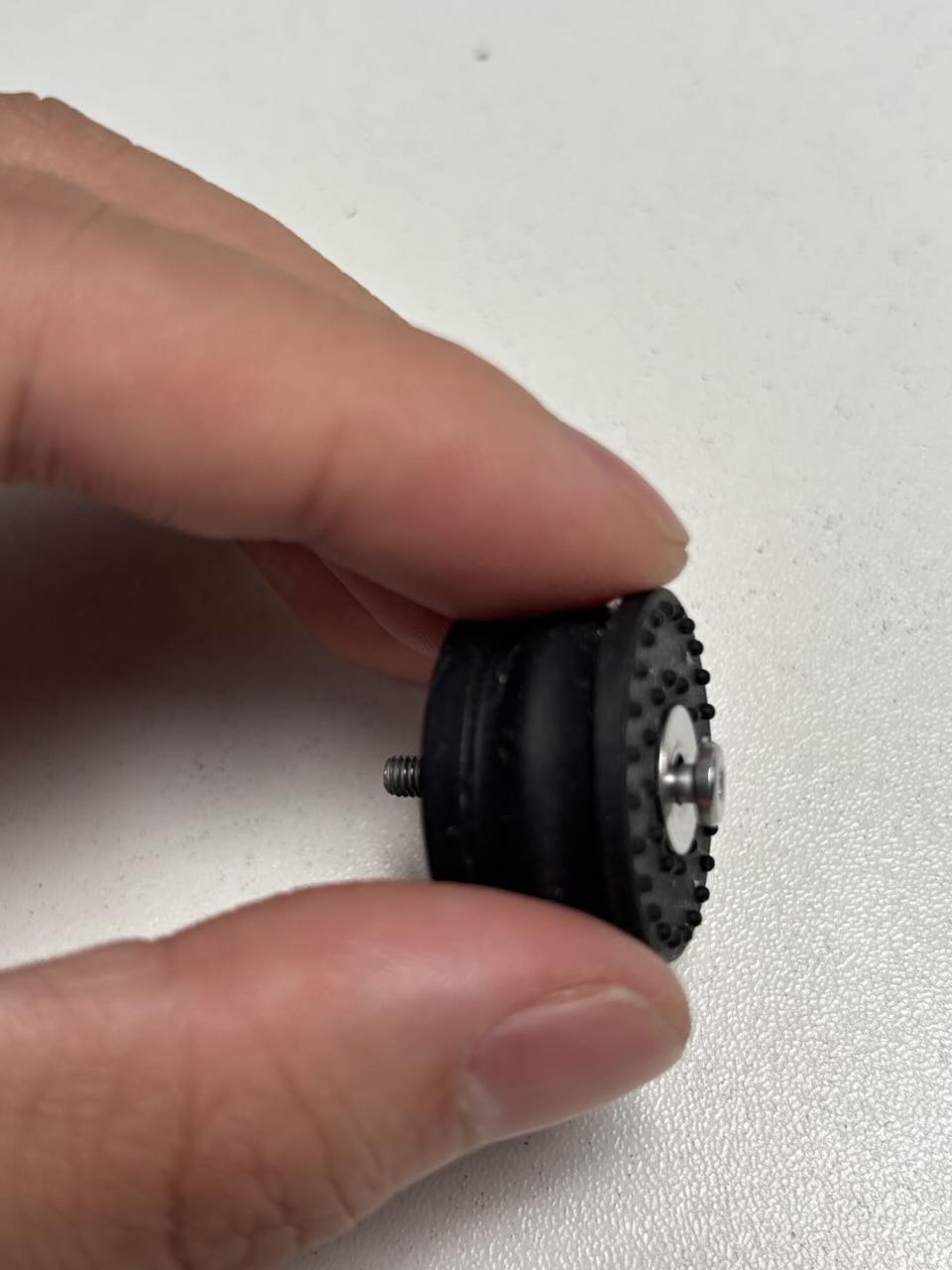
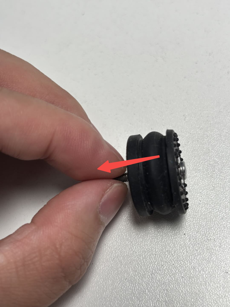
- Peel off the adhesive backing of the new feet, align the screws with the holes, and install the feet and screws together. Press the feet firmly to adhere them to the ring, then use the H2.0 Allen key to tighten the fixing screws (M3x21.5x6).
The remaining three feet can be installed using the same method.

¶ Step 3: Place the printer upright
Place the printer flat on the table, ensuring it is stable and does not wobble.
Given the printer's weight, it is recommended that two people work together to avoid potential damage.
¶ Verify the Functionality
Check that the bottom ring is not floating and all screw holes are installed in place.
¶ End Notes
We hope the detailed guide provided has been helpful and informative.
If this guide does not solve your problem, please submit a technical ticket, we will answer your questions and provide assistance.
If you have any suggestions or feedback on this Wiki, please leave a message in the comment area. Thank you for your support and attention!