¶ Left Side Panel
The left side panel is installed on the left side of the printer (facing the printer), and there is a glass window or left laser safety window on the left side panel.
The spare parts of the left side panel include the following items:
-
Left side panel (with pre-installed glass window or laser safety window);
-
ST3 x 3 screws - used to lock the side panel at the pillar position * 2;
- BT3 x 8 screws - used to lock the left side panel behind the upper frame and auxiliary part cooling fan * 3
¶ When to use
The left side panel is damaged, dented, etc.
¶ Tools and materials needed
-
Left/Right side panel
-
H2.0 Allen key
-
Tweezers
Specifications and quantities of screws involved in replacing the H2D left side panel (it is recommended to keep the removed screws properly to avoid loss):
| Specification | Image | Use | Position | Quantity | |
|---|---|---|---|---|---|
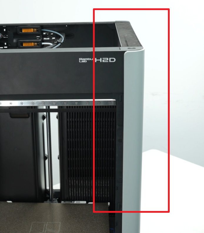
| BT3x8 | Fix the rear panel (marked by the green square) |  |
12 | ||
| Fix the left side panel | 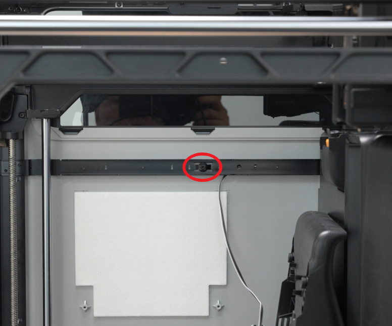 |
 |
3 | ||
| M3x3(Nut diameter 10mm) | Fix the front glass door | 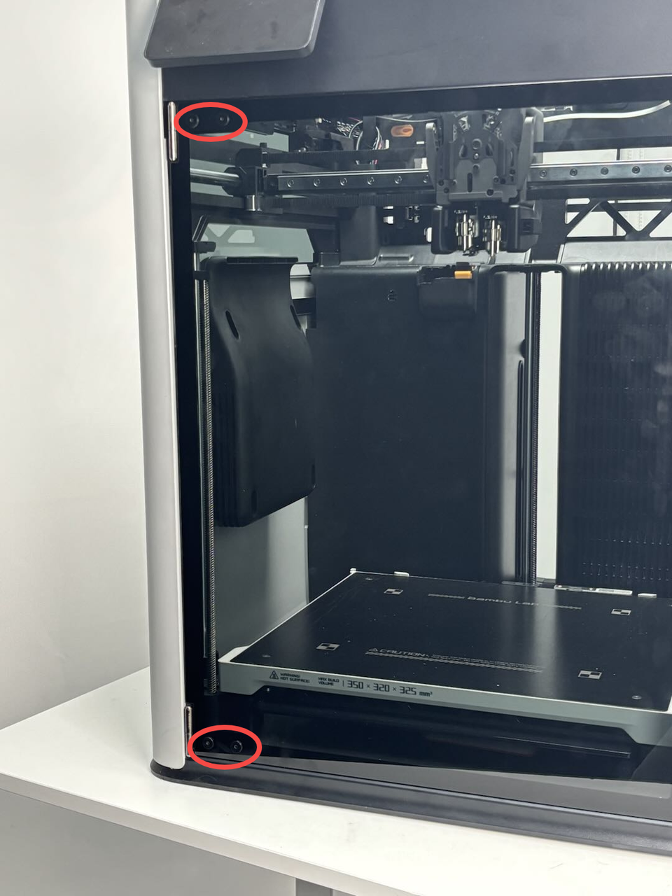 |
4 | ||
| BT3x16 | Fix the auxiliary part cooling fan | 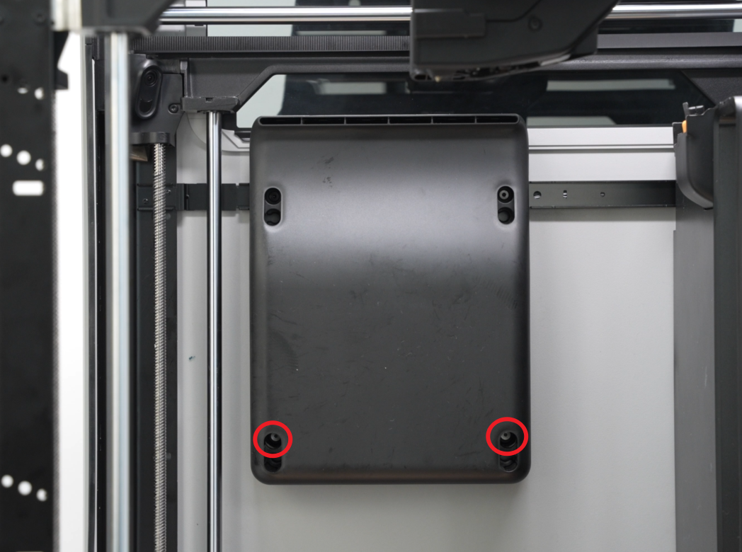 |
2 | ||
| ST3x3 | Fix the left side panel | 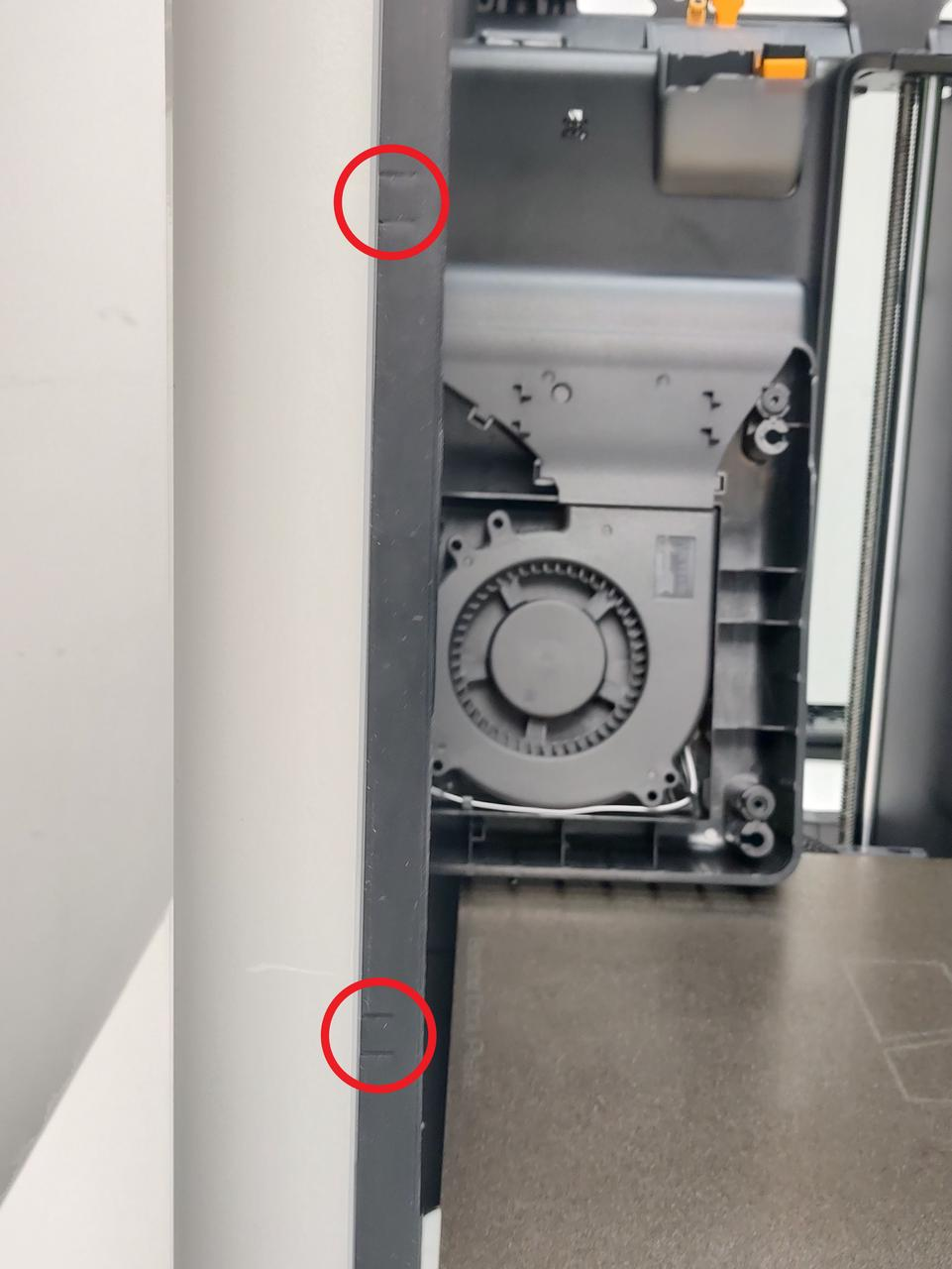 |
2 | ||
| ST3x8 | Fix the rear panel (marked by the red circle) |  |
11 | ||
| ST3x12 | Fix the spool holder bracket (marked by the yellow square) | 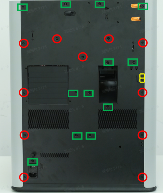 |
2 |
Specifications and quantities of screws involved in replacing the H2D right side panel (it is recommended to keep the removed screws properly to avoid loss):
| Specification | Image | Use | Position | Quantity | |
|---|---|---|---|---|---|
| BT3x8 | Fix the rear panel |  |
12 | ||
| Fix the right side panel | 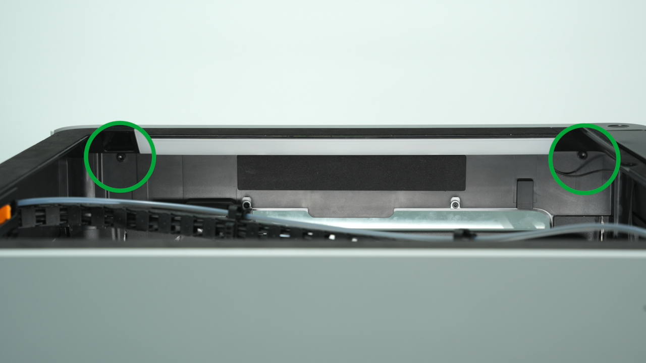 |
2 | |||
| ST3x8 | Fix the rear panel |  |
11 | ||
| ST3x12 | Fix the spool holder bracket |  |
2 | ||
| ST3x3 | Fix the right side panel | 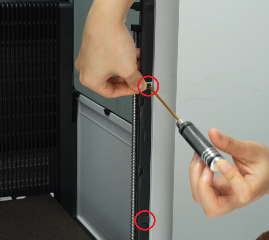 |
2 |
¶ Safety Warning
IMPORTANT!
It's crucial to power off the printer before conducting any maintenance work, including work on the printer's electronics and tool head wires. Performing tasks with the printer on can result in a short circuit, leading to electronic damage and safety hazards.
During maintenance or troubleshooting, you may need to disassemble parts, including the hotend. This exposes wires and electrical components that could short circuit if they contact each other, other metal, or electronic components while the printer is still on. This can result in damage to the printer's electronics and additional issues.
Therefore, it's crucial to turn off the printer and disconnect it from the power source before conducting any maintenance. This prevents short circuits or damage to the printer's electronics, ensuring safe and effective maintenance. For any concerns or questions about following this guide, we recommend submitting a technical ticket regarding your issue and we will do our best to respond promptly and provide the assistance you need.
¶ Video Guide
¶ Remove the Left Side Panel
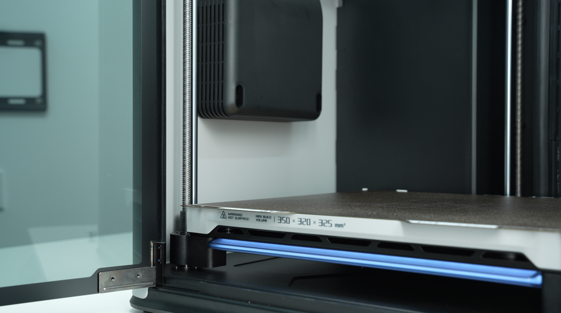
¶ Step 1: Lower the Heatbed
Control the heatbed through the screen and lower it to the bottom of the printer.
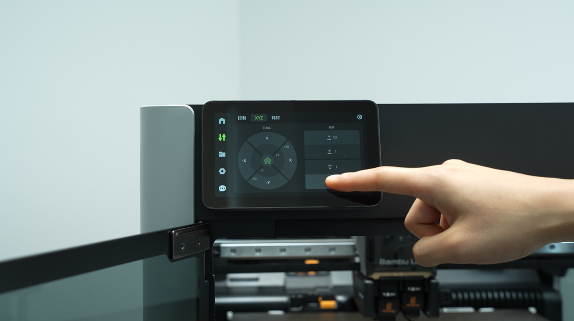
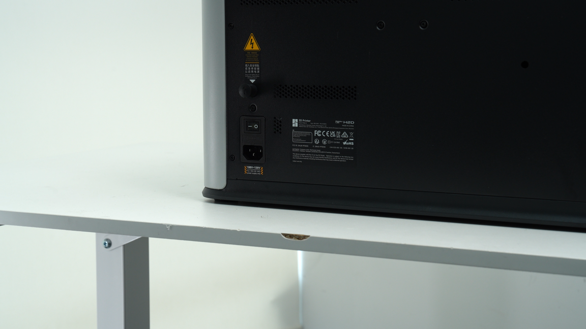
After lowering the heatbed, turn off the printer and disconnect the power.
¶ Step 2: Remove the Rear Panel
Before removing the left side panel, you need to remove the rear panel first. You can refer to this Wiki to remove the H2D rear panel:
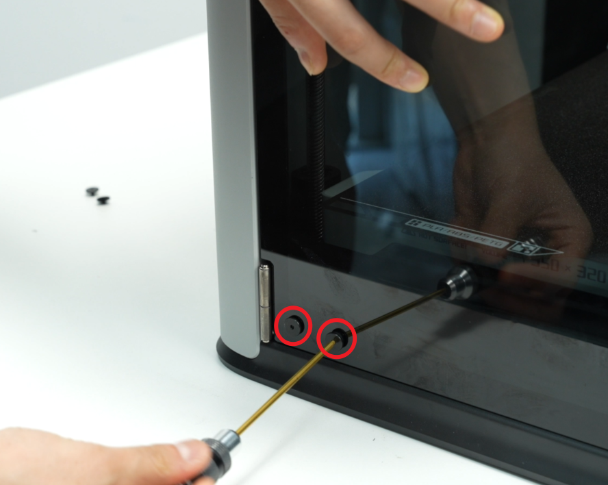
¶ Step 3: Remove the Front Glass Door/Front Laser Safety Window
Use an H2.0 Allen key to remove the 4 screws (M3x3, nut diameter 10mm) that secure the front door, 2 screws on the top and 2 screws on the bottom, then hold the front glass door with one hand and remove the front door.
Be sure to hold the front glass door with your hand to prevent it from falling.


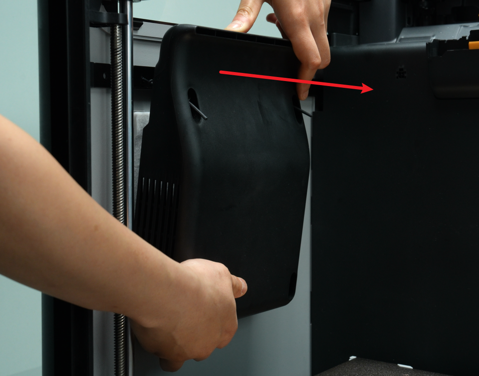
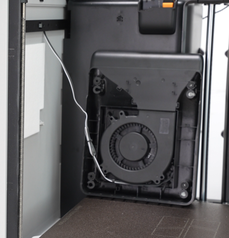
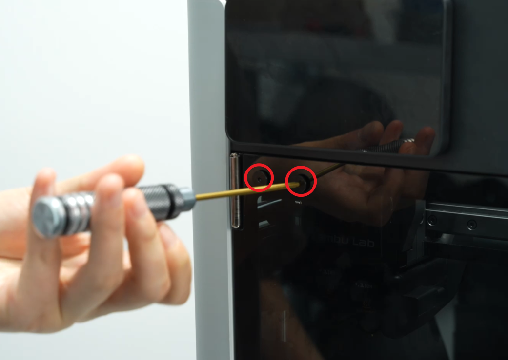
¶ Step 4: Remove the Auxiliary Part Cooling Fan
You need to remove the auxiliary part cooling fan first because there is a side panel fixing screw behind the auxiliary part cooling fan.
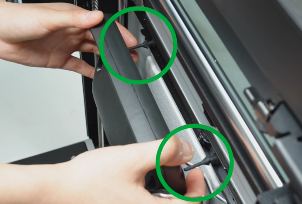
The auxiliary part cooling fan is fixed with soft screws (two in the upper row) and screws (two in the lower row). You can use an H2.0 Allen key to remove the two fixing screws (BT3x16) in the lower row, pull the fan hard to remove the soft screws, and then place the fan on the heatbed without disconnecting the connectors from the MC board.

You can also refer to this wiki for detailed steps on removing the auxiliary part cooling fan:
Replace H2D Auxiliary Part Cooling Fan
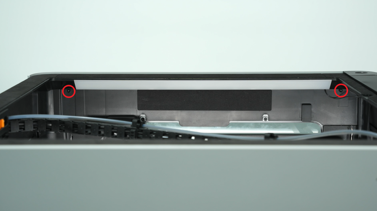
¶ Step 5: Remove the Left Side Panel Fixing Screws
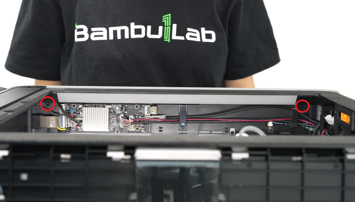
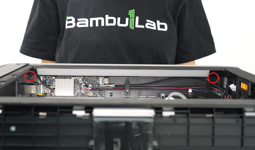
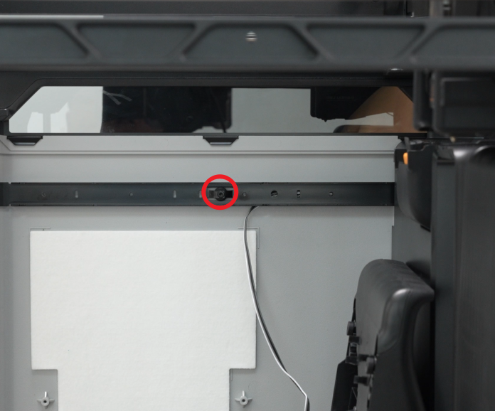
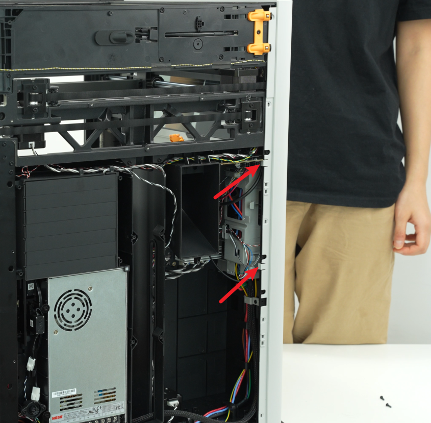
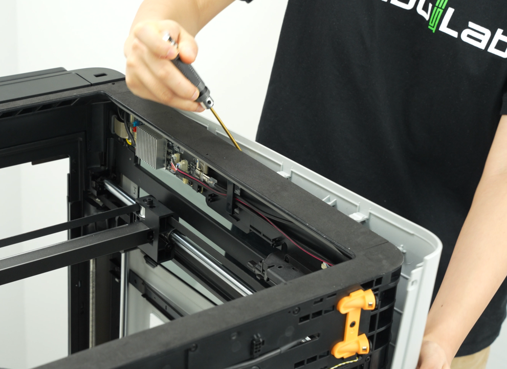
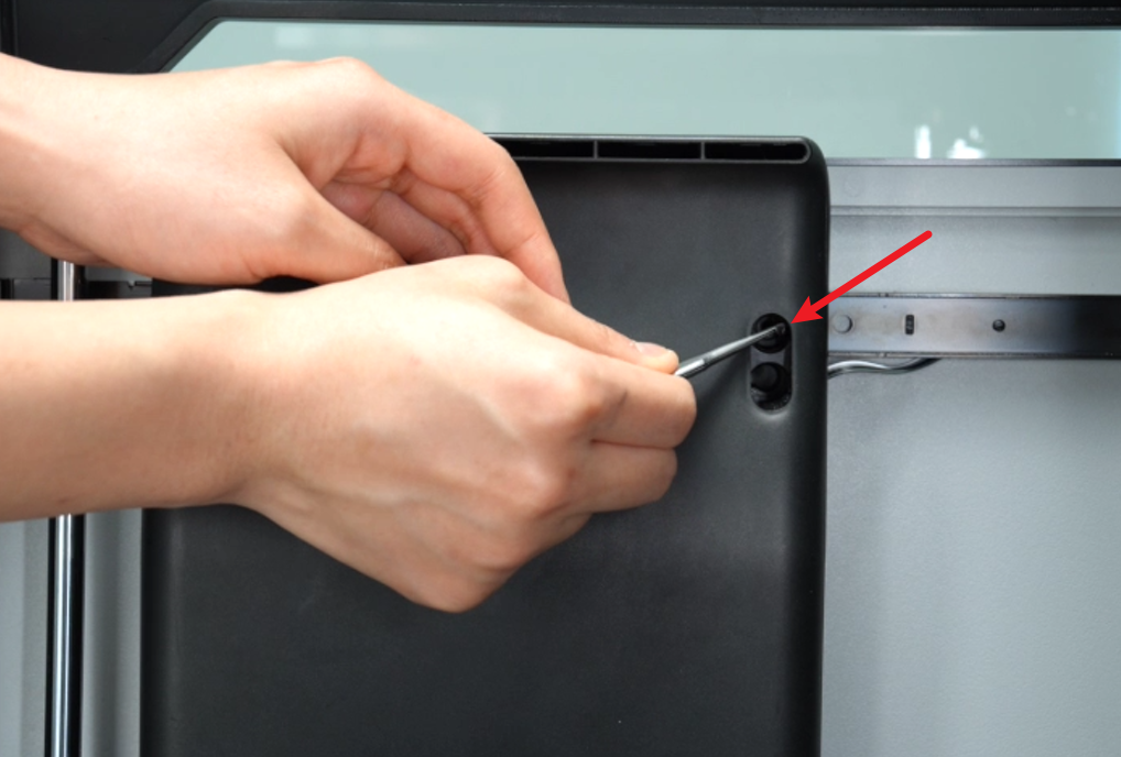
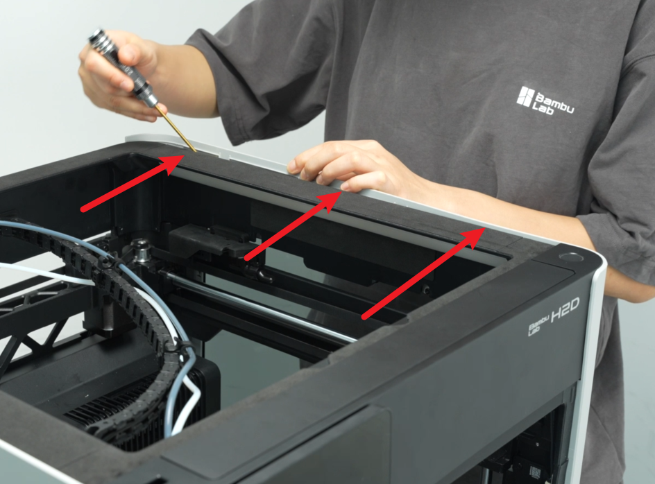
- Use an H2.0 Allen key to remove the two fixing screws (BT3×8) that lock the upper frame and one fixing screw (BT3×8) that locks the beam.
Note: The corresponding holes are reserved on the AP board. The two fixing screws of the upper frame can be removed without removing the AP board. The following figure shows the AP board removed for easy shooting.
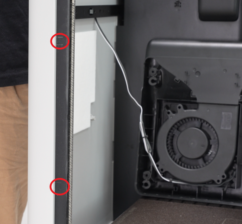
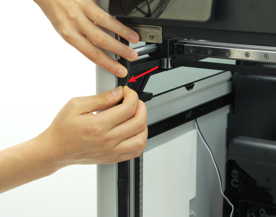
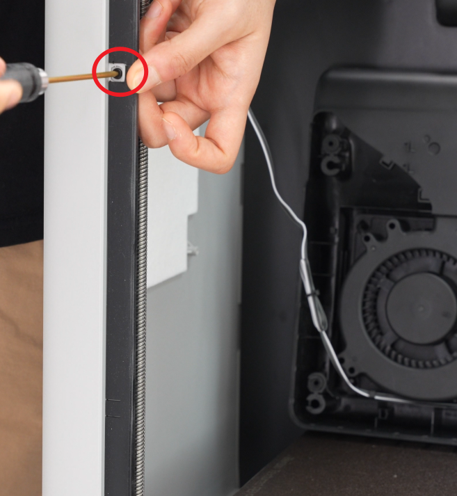
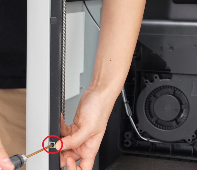
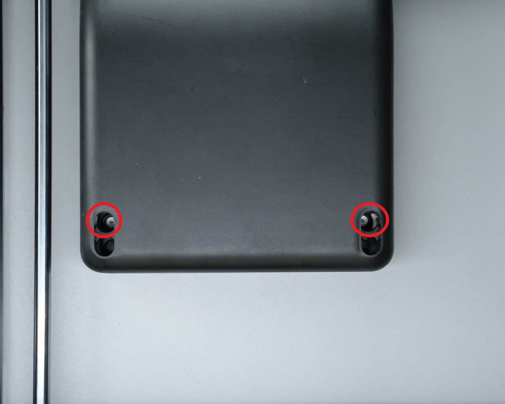
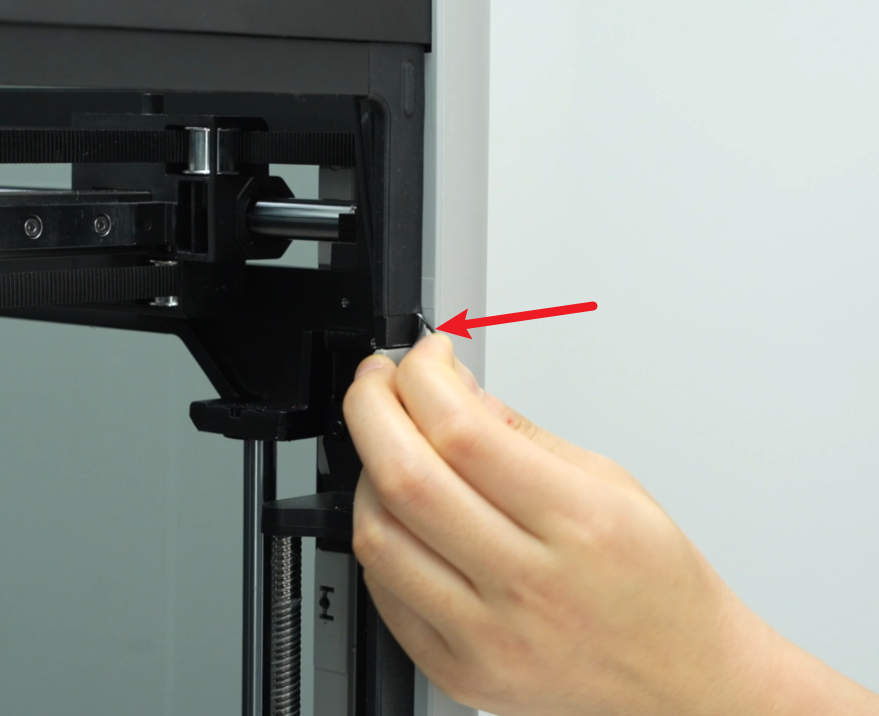
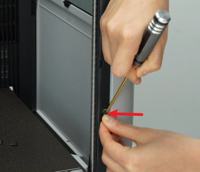
- Two screws (M3×3) locked on the pillar. These screws are behind the rubber strip. You need to pry open the rubber strip from its opening, and then you can see the screws.


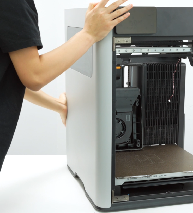
¶ Step 6: Remove the Left Side Panel
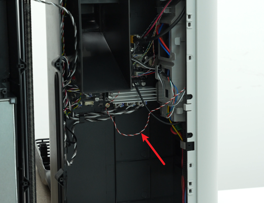
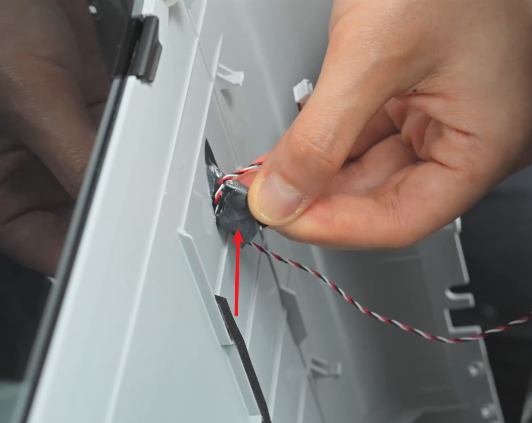
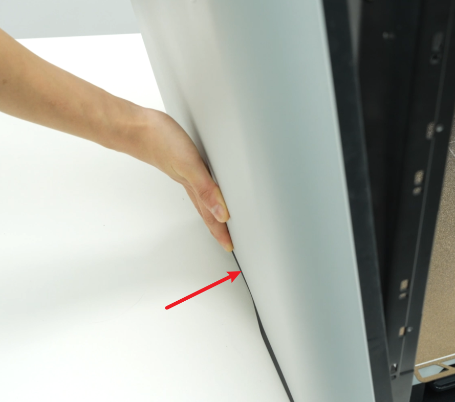
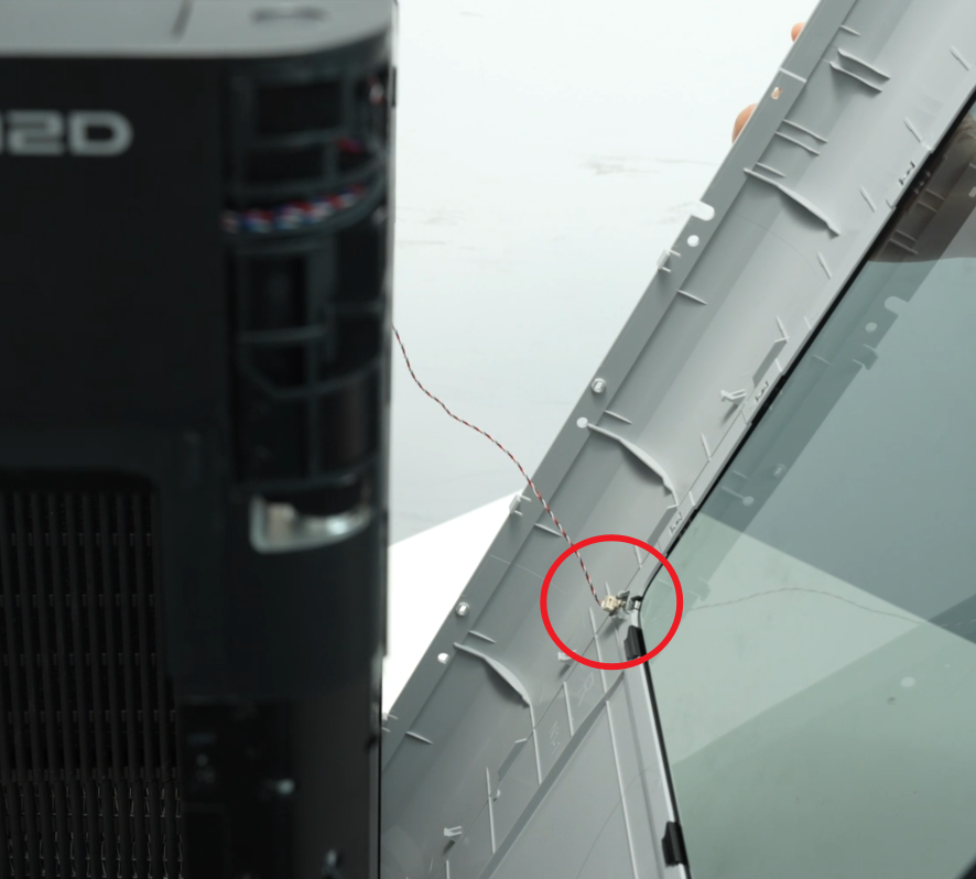
- In addition to screws, the left side panel is also fixed to the printer with buckles. Before opening the left side panel, please tear off the silicone on the left side panel and loosen the hall connector of the left side panel from the cable buckle of the AC board cable cover to avoid breaking the cable when opening the side panel.
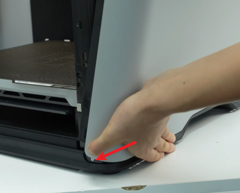
- Then you can first open the buckle at the back of the printer;
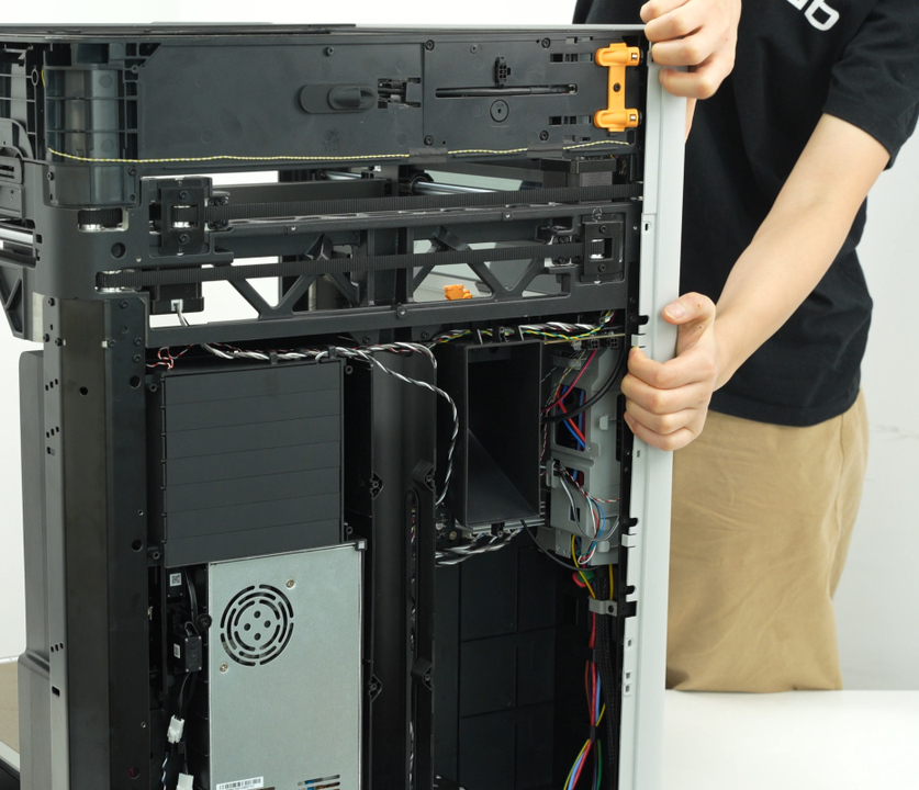
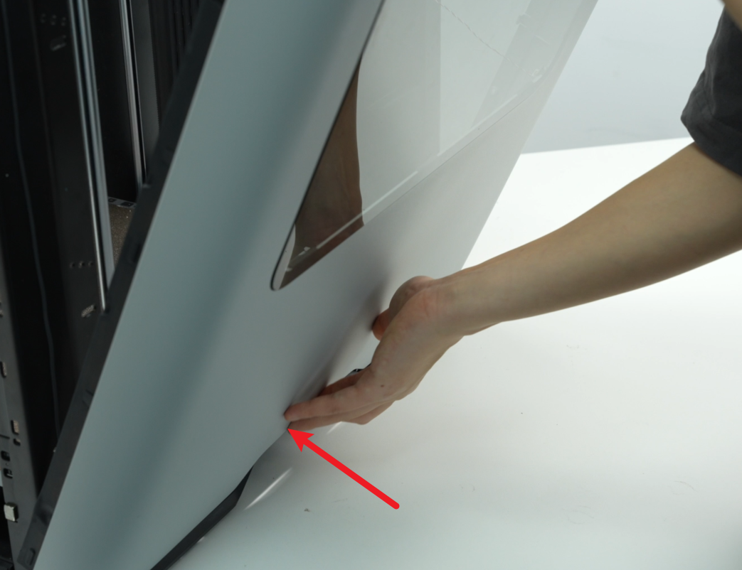
- Then you can use the Allen key to pry open the buckle on the top of the left side panel, pry open the left side panel from the front, disconnect the hall connector of the left side panel, tear off the tape on the left side panel, and then remove the left side panel.
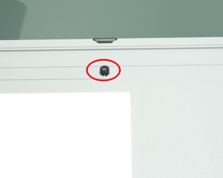
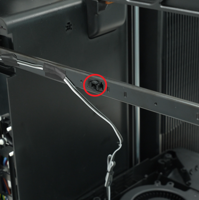
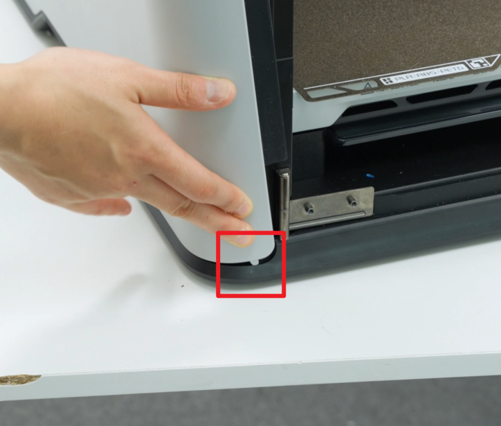
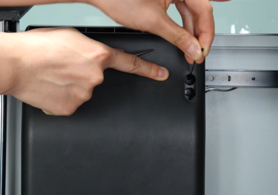
- Please note that there is a round silicone plug in the screw hole behind the auxiliary part cooling fan. Be careful when removing the side panel to avoid losing it.


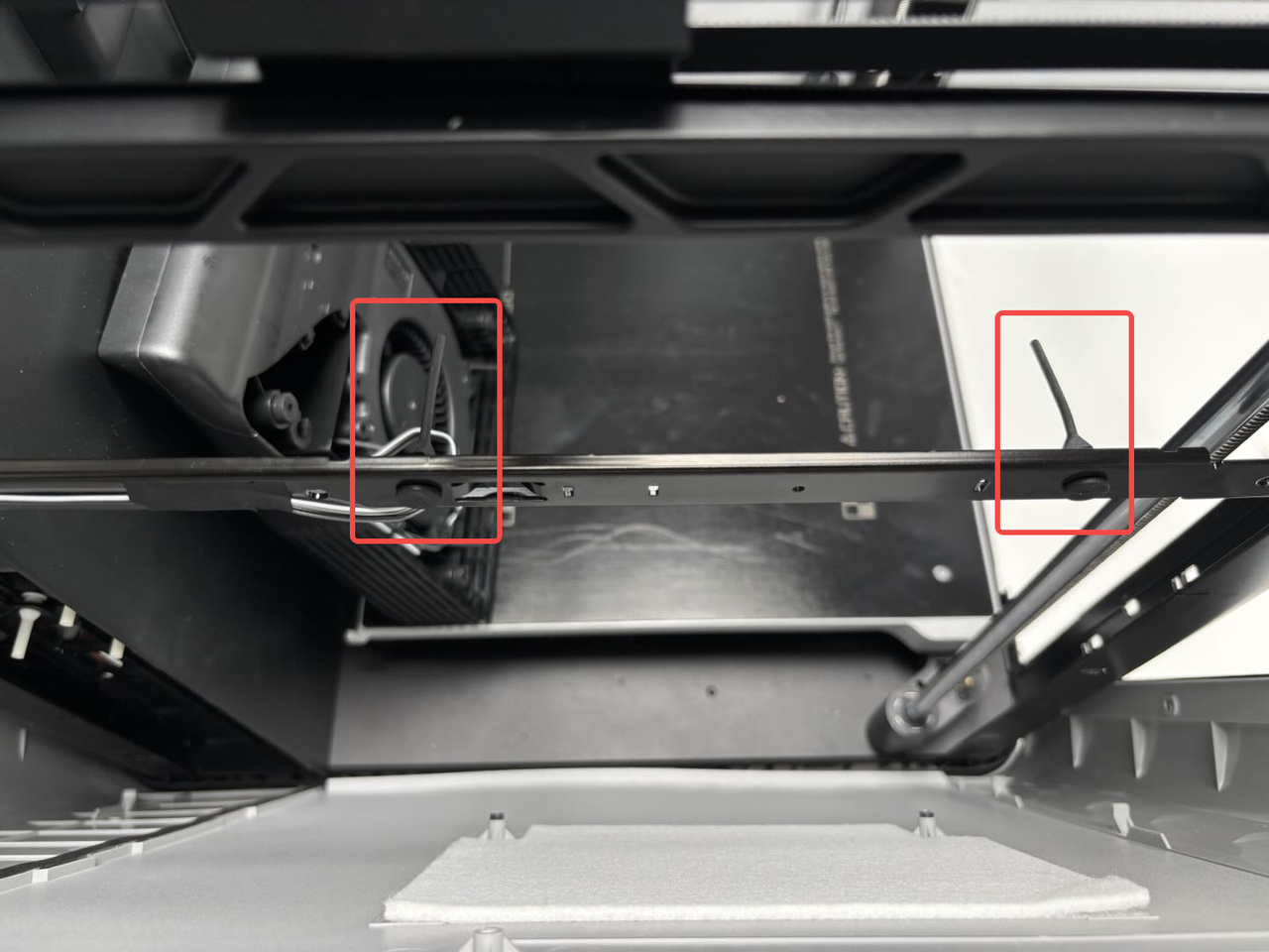
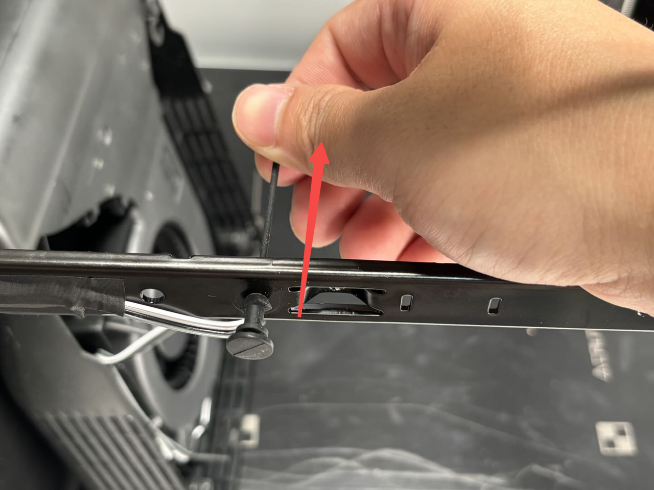
¶ Step 7: Remove the Soft Screws of Auxiliary Part Cooling Fan (Optional)
If your soft screws are not damaged or are long enough to pass through the auxiliary part cooling fan, you can ignore this step and do not need to replace the soft screws.
You can remove the two soft screws from the printer beam by pulling them on the outside.
¶ Install the Left Side Panel
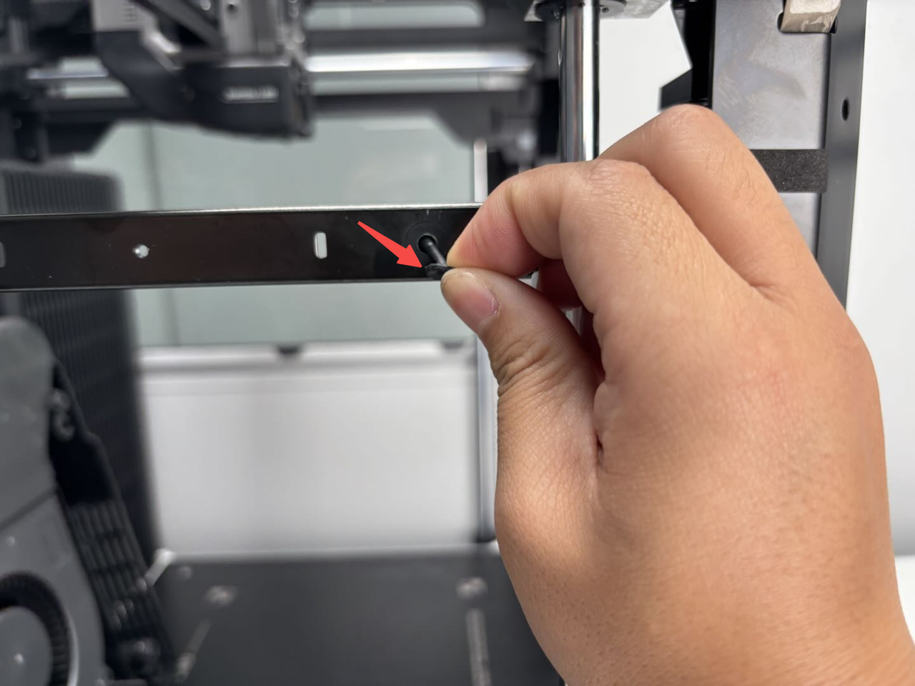
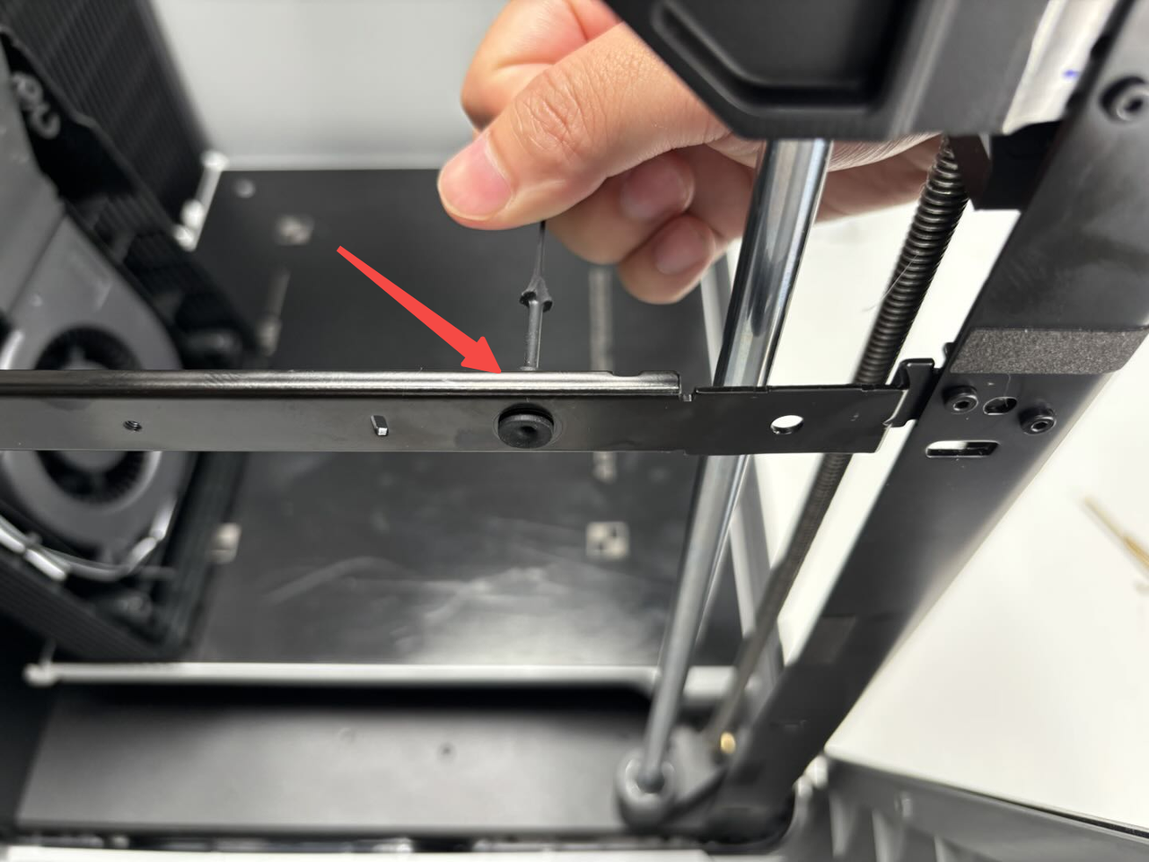
¶ Step 1: Install the Soft Screws of Auxiliary Part Cooling Fan (Optional)
If your soft screws are not damaged or are long enough to pass through the auxiliary part cooling fan, you can ignore this step and do not need to replace the soft screws.
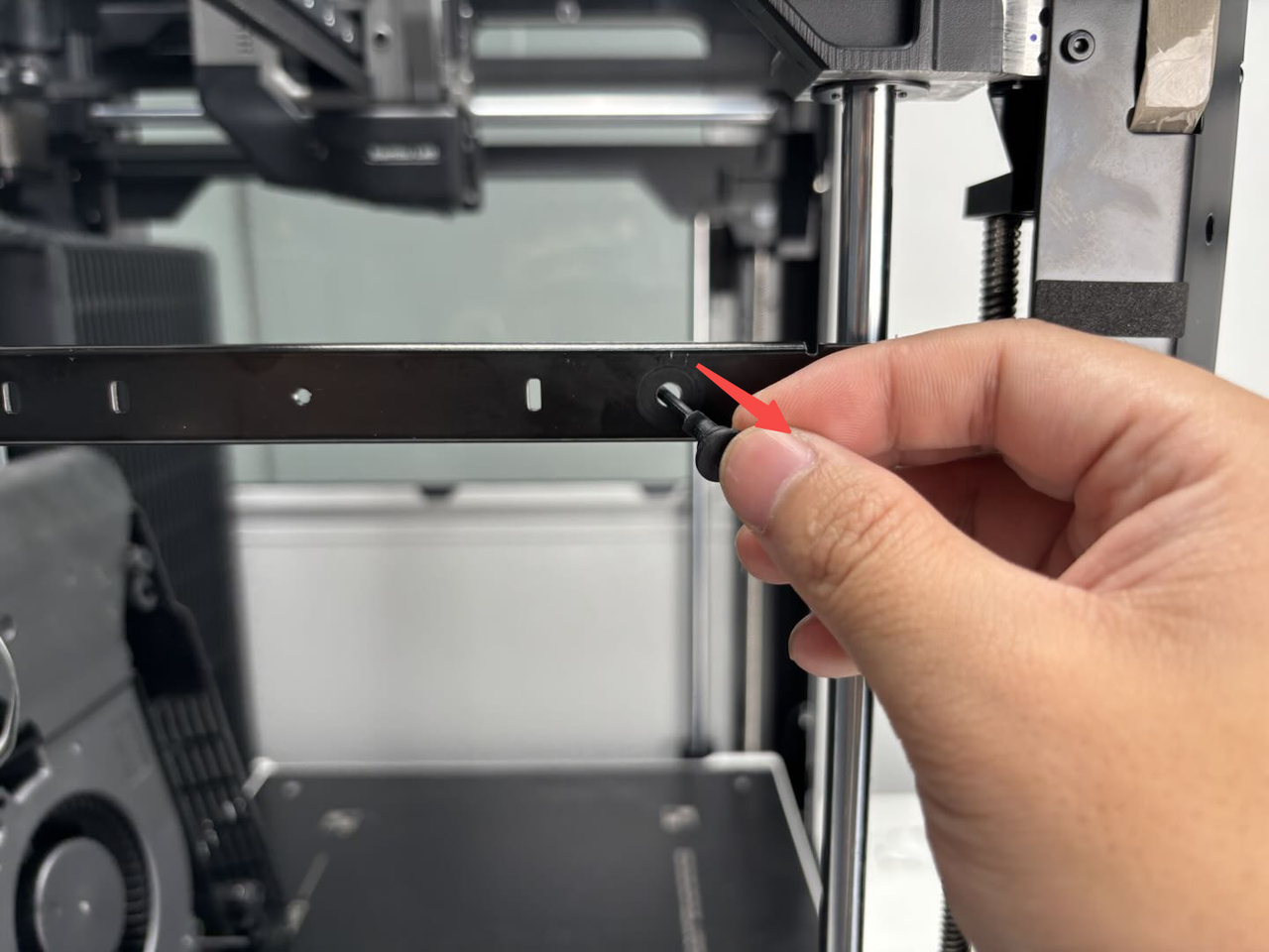
Insert the soft screw through the small hole in the beam and pull the soft screw until it snaps into the beam.
¶ Step 2: Secure the Clips of the Left Side Panel
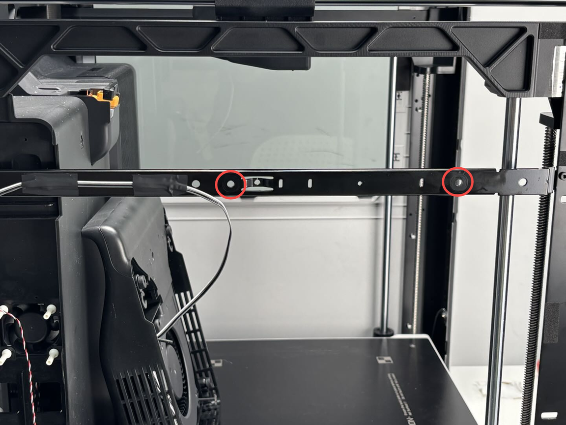
- Before installation, please check whether the silicone plug at the screw hole of the beam is installed in place. If not, please check whether it is left on the left beam of the printer;
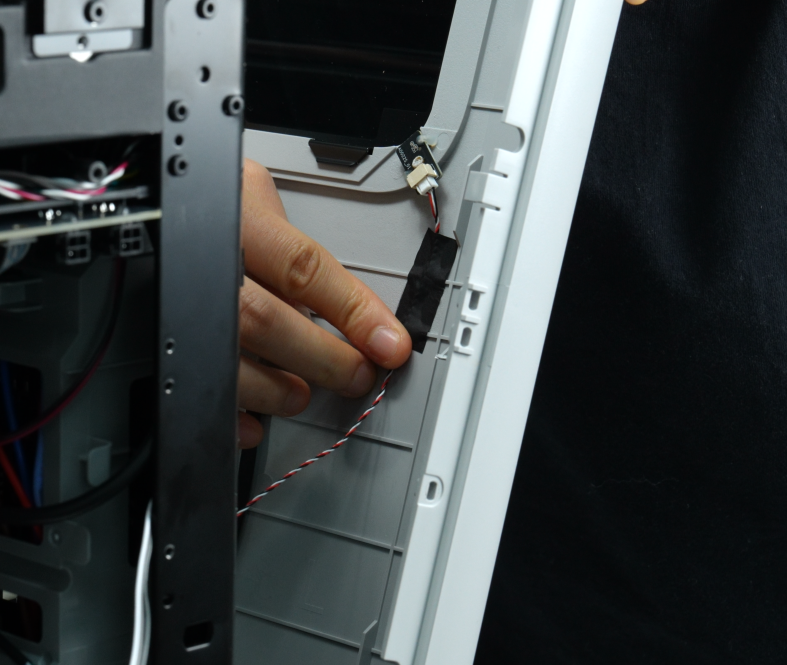
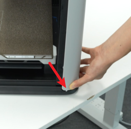
- Align the two large pins at the bottom of the left side panel with the corresponding small holes at the bottom of the printer and insert them, then connect the hall effect sensor on the left side panel to the hall connector, and re-stick the tape that sticks the hall connector to the side panel;
It is recommended to push the buckle on the back of the printer first, as these clips do not have fixed tabs, making them easier to push in.
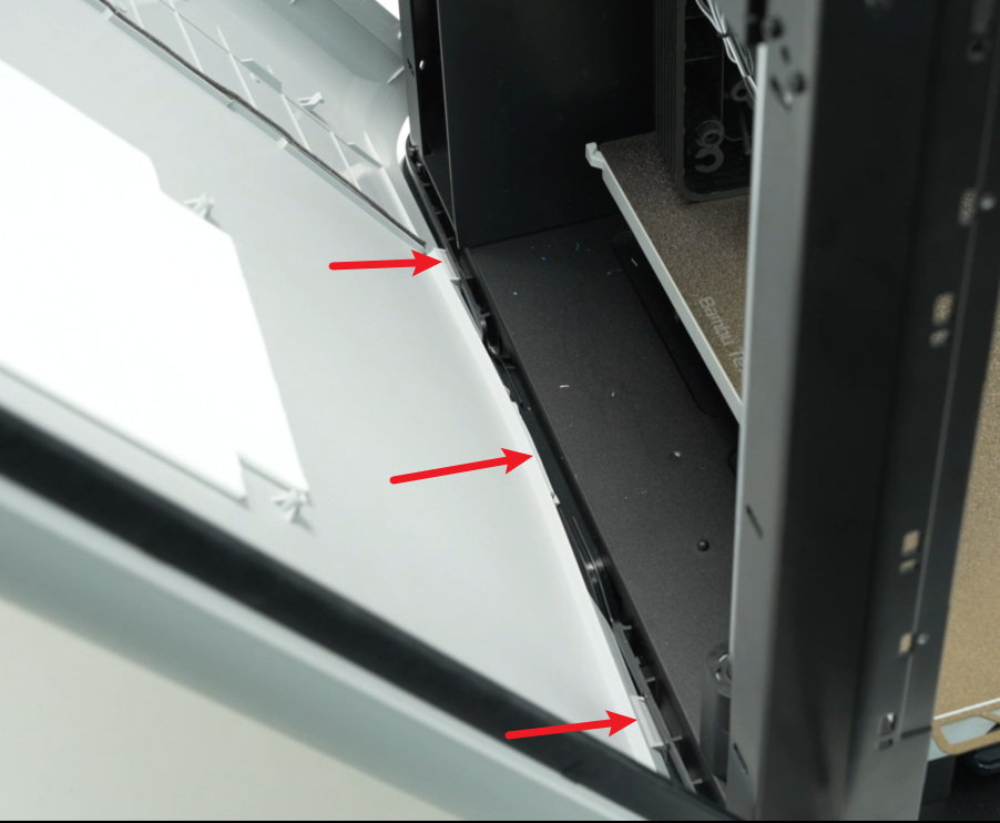
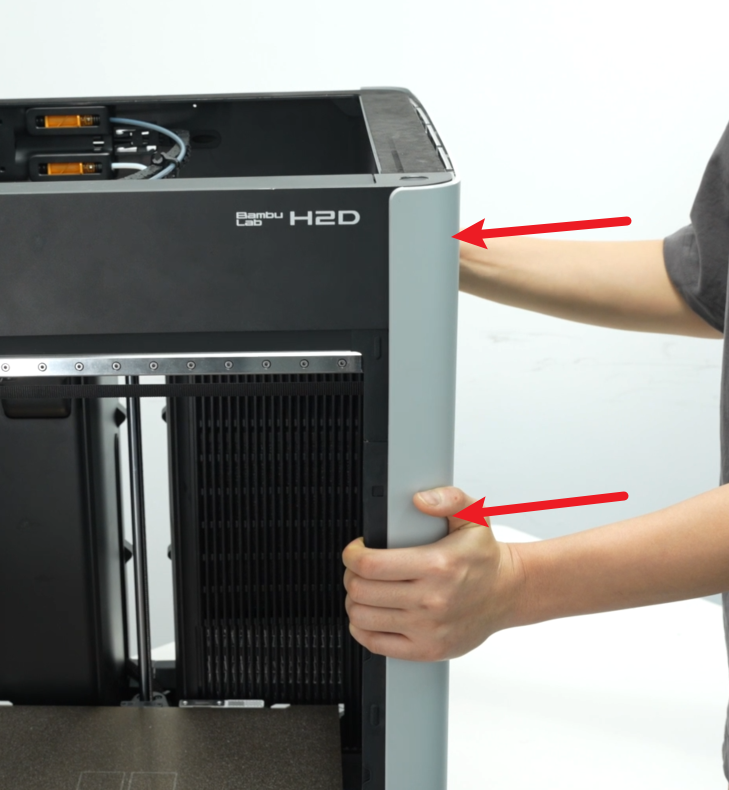
- Push the left side panel upwards slowly, hold the armrest with your hand, insert the buckle of the armrest into the bottom of the printer, and then insert the two small buckles near the front door and the back into the corresponding small holes at the bottom of the printer;
- After installing the bottom of the left side panel, please check whether all the buckles at the bottom are in place and not floating. Then push the right side panel inward and secure all the buckles in place.
The buckles are redundantly designed. If they break during the disassembly and assembly process, it will not affect normal use. It is fine as long as there is no floating.
¶ Step 3: Tighten the Left Side Panel Fixing Screws
- Use an H2.0 Allen key to tighten the two screws (BT3x8) on the inside of the left side panel, and then use an H2.0 Allen key to tighten the one screw (BT3×8) fixed to the beam;


- Pry open the opening on the silicone strip and tighten the two fixing screws (ST3x3) with an H2.0 Allen key;
If the opening is difficult to tear open, you can use an Allen key to assist in prying it open.

¶ Step 4: Install the Auxiliary Part Cooling Fan
Method One:
- Pass the soft screw through the small hole near the inside of the auxiliary part cooling fan, then pull the soft screw by hand to fix the top of the auxiliary part cooling fan with the soft screw; install the soft screw on the outside after the inside is installed;
Note:
You can hear a "click" sound when the soft screw is pulled into place;
The soft screw is made longer at the factory for easy installation. After installation, you can use scissors to cut off some of it for a better appearance.
- Use an H2.0 Allen key to tighten the two bottom fixing screws.
Note: The fixing screws of the H2D auxiliary part cooling fan are all located in the small holes on the top.

Method Two:
- Align the auxiliary part cooling fan with the screw holes on the left panel, then use an H2.0 Allen key to tighten the two bottom fixing screws (BT3x16);
- Gently pull apart the auxiliary part cooling fan with both hands, align the two screw holes at the top of the fan with the soft screws, and insert the soft screws into the holes.
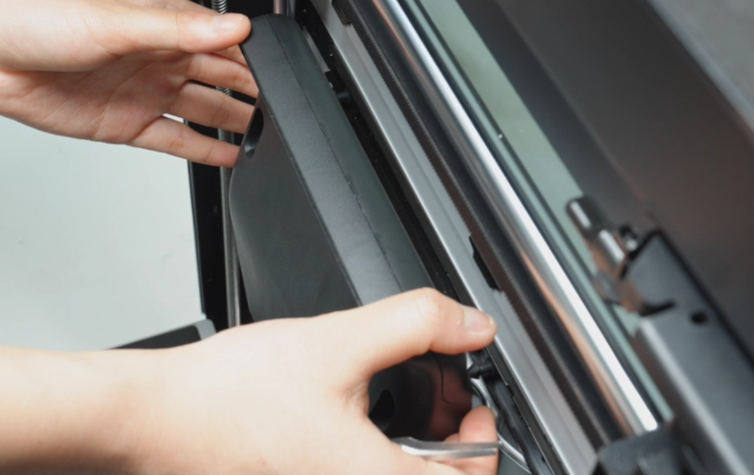
- Use tweezers to pull out the soft screws slightly, then pull the soft screws to secure the fan in place.
¶ Step 5: Install the Front Glass Door/Front Laser Safety Window
Align the 4 screw holes on the front door with the screw holes on the hinge, hold the front glass door steady with your hands, and use an H2.0 Allen key to tighten the 4 screws (M3x3, nut diameter 10mm).
¶ Step 6: Install the Rear Panel
You can refer to this Wiki to replace the rear panel:
¶ Remove the Right Side Panel
¶ Step 1: Remove the rear panel
You can refer to this Wiki to remove the H2D rear panel:
¶ Step 2: Remove the screws
- Pry open the opening on the silicone strip and use an H2.0 Allen key to remove the two fixing screws (ST3x3);
If the opening is difficult to tear, you can use an Allen key to assist in prying it open.


- Use an H2.0 Allen key to remove the two fixing screws (BT3x8) on the inside of the side panel.
¶ Step 3: Remove the right side panel
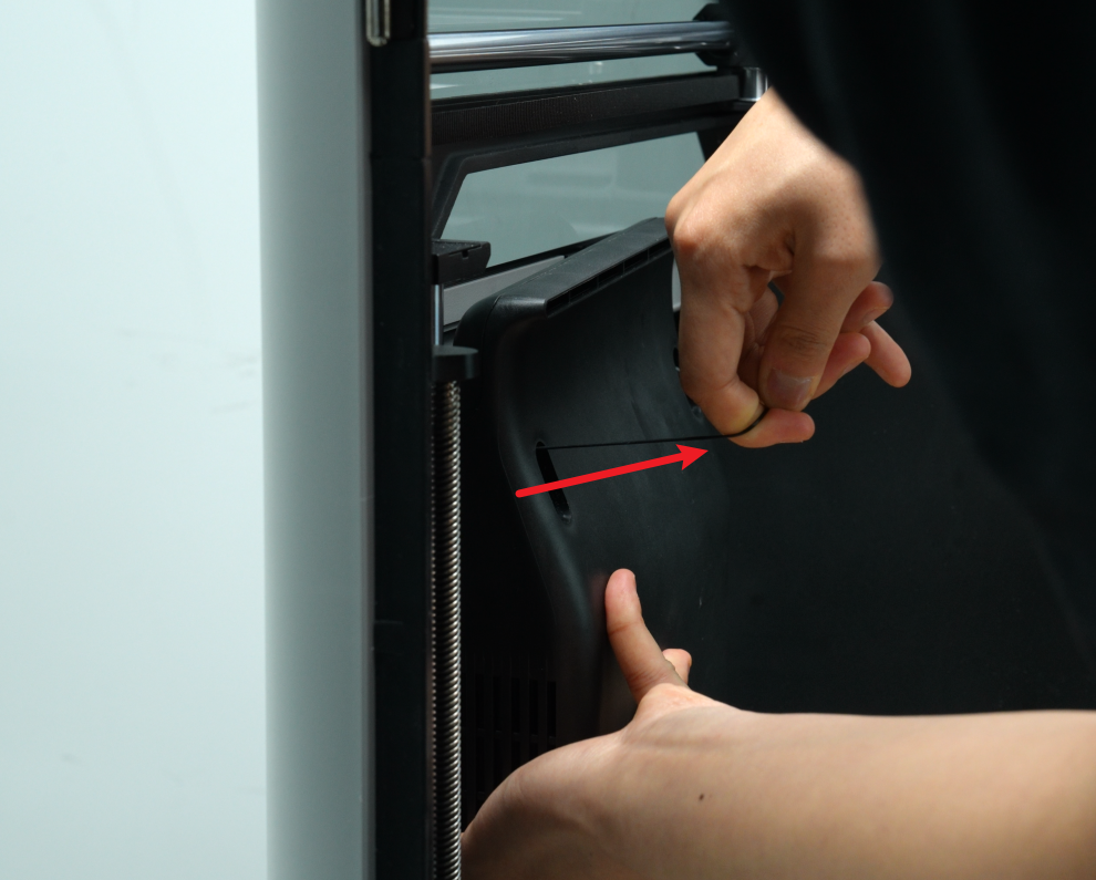
- Tear off the adhesive strips on the side panels and the frame to facilitate the subsequent removal of the right side panel;
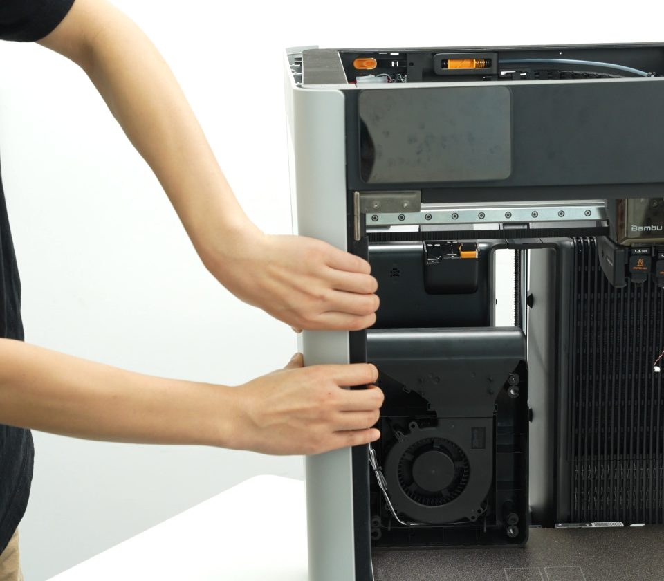
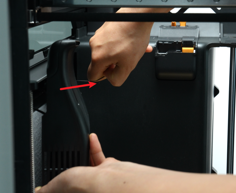
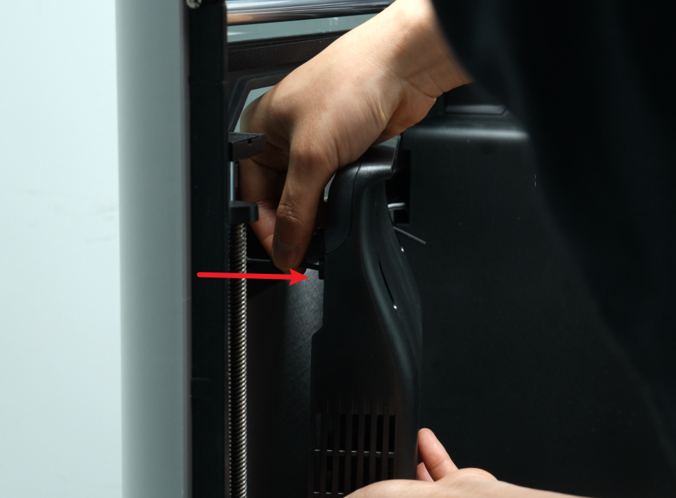
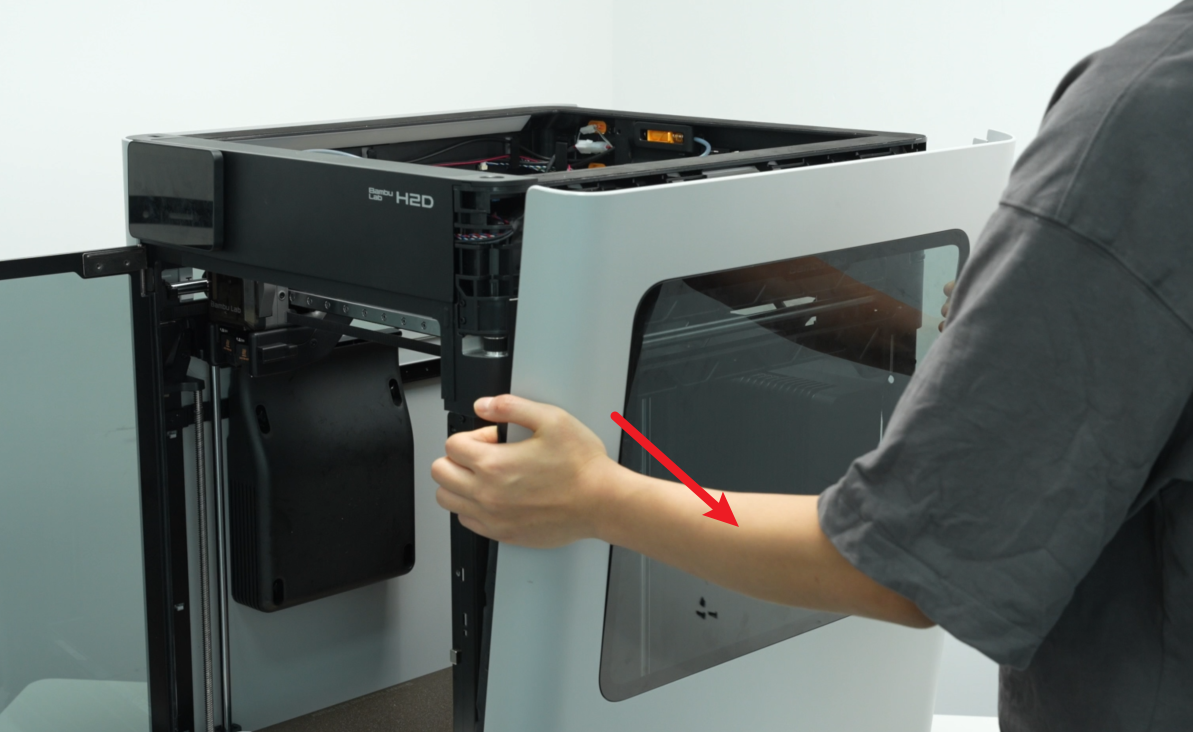
- Hold the right side panel near the back of the printer with both hands, pry the side panel open to unlock the buckle, and then unlock the buckle on the top (you can use an Allen key to help pry open the top buckle) and the buckle on the front door side in turn;
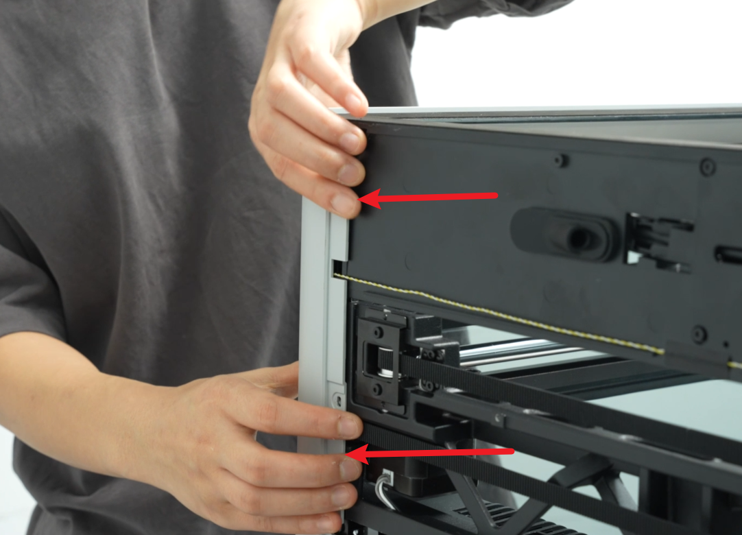
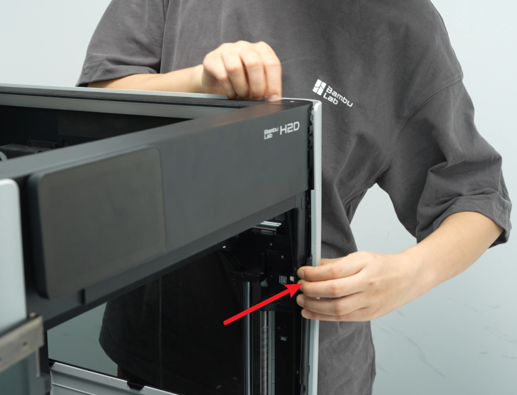
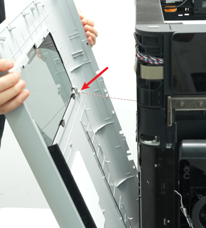
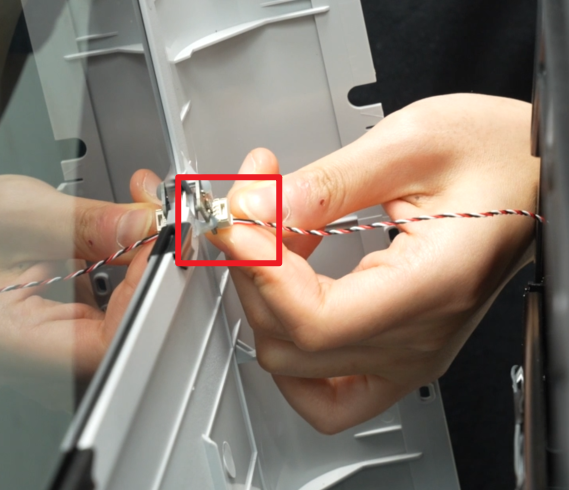
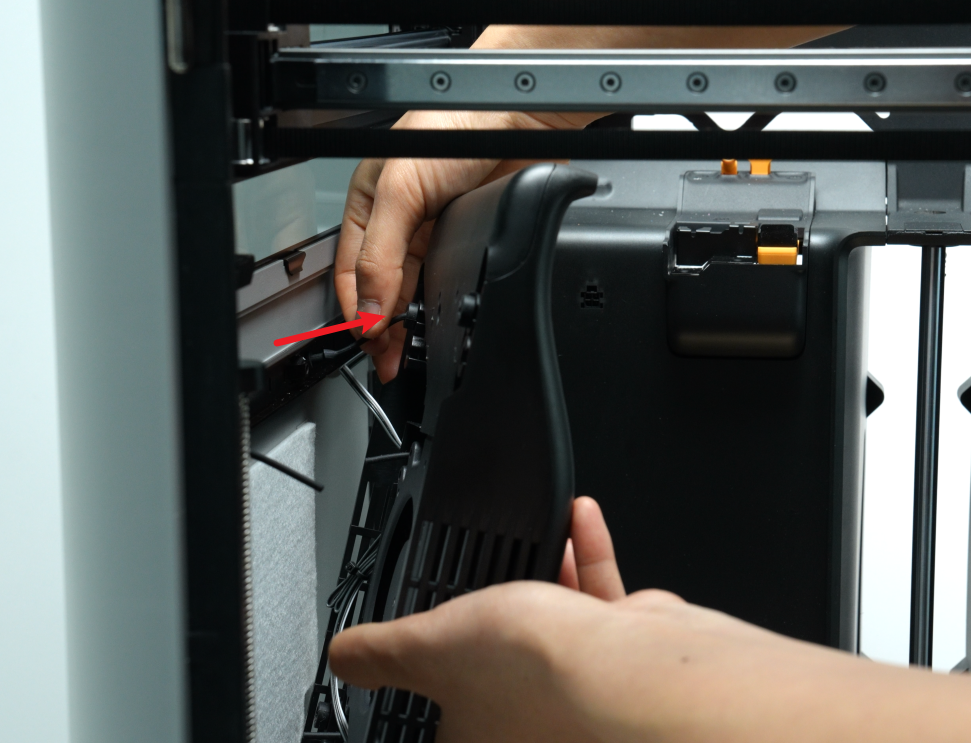
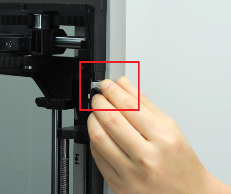
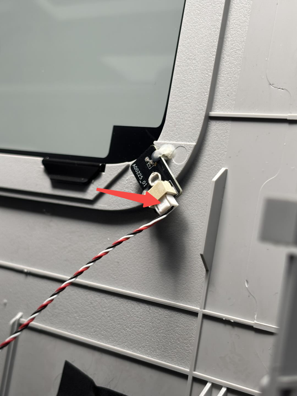
- Hold the right side panel with both hands and slowly pull it down until you can see the hall effector sensor connector on the right side panel, then press the buckle on the interface (as shown by the arrow) to disconnect the hall effector sensor connector from the hall effector sensor, and finally pull out the right side panel diagonally.
Note: Do not use force to directly remove the side panel to avoid breaking the hall effector sensor connector.

¶ Install the right side panel
¶ Step 1: Fasten the buckle of the right side panel
- Align the two large pins at the bottom of the right side panel with the corresponding small holes at the bottom of the printer and insert them, then connect the hall effect sensor on the right side panel to the hall effect sensor connector;
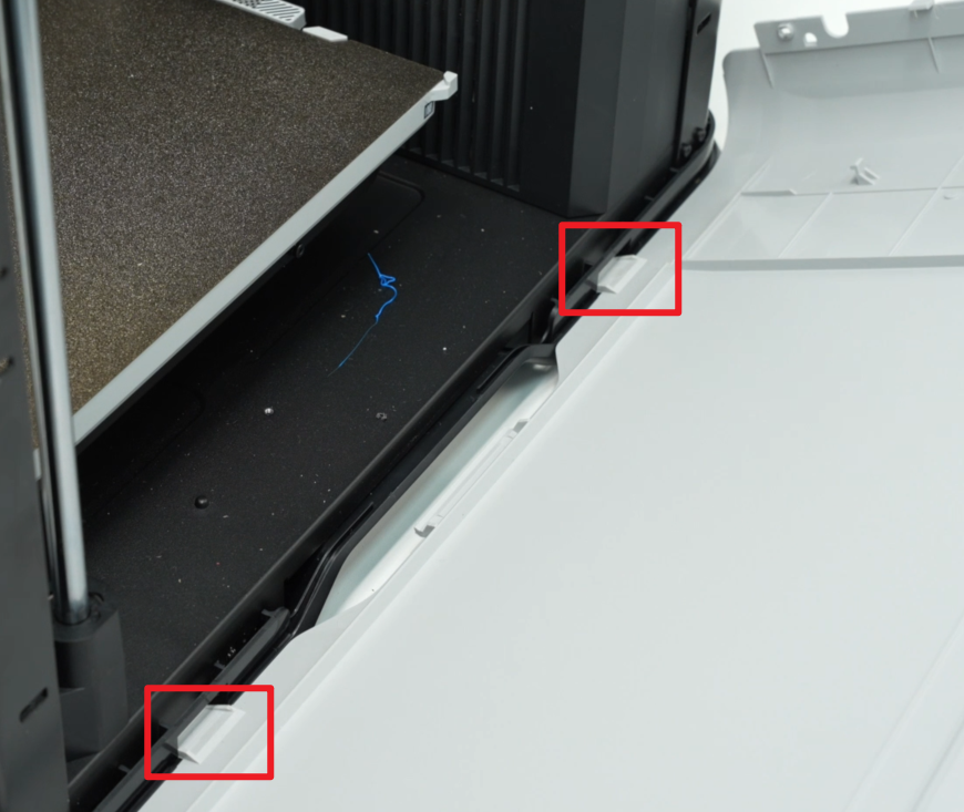
- Push the right side panel upwards slowly, hold the armrest with your hands, insert the buckle of the armrest into the bottom of the printer, and then insert the two small buckles near the front door and the back into the corresponding small holes at the bottom of the printer;
- After installing the bottom of the right side panel, please check whether all the buckles at the bottom are in place and not floating. Then push the right side panel inwards and buckle all the buckles in place.
¶ Step 2: Tighten the screws
- Use an H2.0 Allen key to tighten the two screws (BT3x8) on the inside of the right side panel;

- Pry open the opening on the silicone strip and use an H2.0 Allen key to tighten the two fixing screws (ST3x3);
If the opening is difficult to tear, you can use an Allen key to assist in prying it open.

¶ Step 3: Install the rear panel
You can refer to this Wiki to install the H2D rear panel:
¶ Verify the Functionality
After installation, the side panel will not float up and all the clips will be buckled into the printer.
¶ End Notes
We hope the detailed guide provided has been helpful and informative.
If this guide does not solve your problem, please submit a technical ticket, we will answer your questions and provide assistance.
If you have any suggestions or feedback on this Wiki, please leave a message in the comment area. Thank you for your support and attention!