¶ Extruder Hall Sensor Board/2004 Switching Motor Unit
There are hall effect sensors on the sides of the quick change tool interface and the dual extruder idlers. The signals of these hall effect sensors will first pass through the extruder hall sensor board and then connect to the TH board.
2004 switching motor is pre-installed on the extruder rear cover. The switching motor is used to switch the left and right hotends.
The spare parts for the extruder hall sensor board include the following:
-
Extruder hall sensor board * 1
-
Extruder hall sensor board FPC * 1
-
ST2x3.5 screw (used to fix the extruder hall sensor board) * 1
-
BT2x5 screw (used to fix the extruder idler side FPC) * 2
The spare parts for the 2004 switching motor unit include the following:
- 2004 switching motor unit (pre-installed on the extruder rear cover) * 1
¶ When to use
-
Extruder hall sensor board malfunctions.
-
Extruder hall sensor board FPC is damaged.
-
Switching motor malfunctions.
¶ Tools and materials needed
-
New extruder hall sensor board
-
H2.0 Allen key
-
H1.5 Allen key
-
Tweezers
Specifications and quantities of screws involved in replacing the H2D Extruder Hall Sensor Board/2004 Switching Motor Unit (it is recommended to keep the removed screws properly to avoid loss):
| Specification | Image | Use | Position | Quantity | |
|---|---|---|---|---|---|
| M2.5x7 | Fix the dual extruder filament guide (marked by the red circles) |  |
3 | ||
| Fix the quick change tool interface | 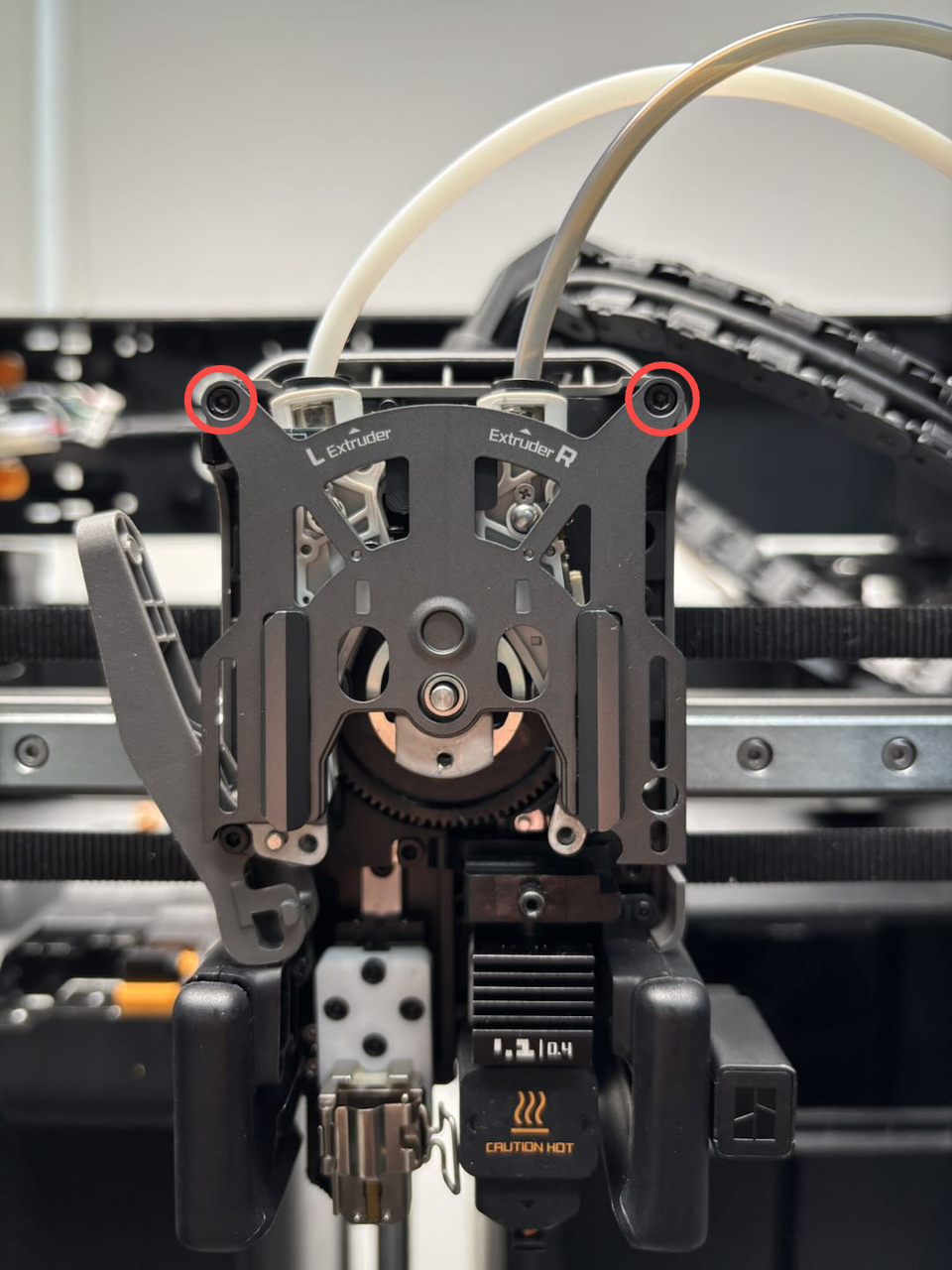 |
2 | |||
| BT2x6 | Fix the dual extruder filament guide (marked by the green squares) | 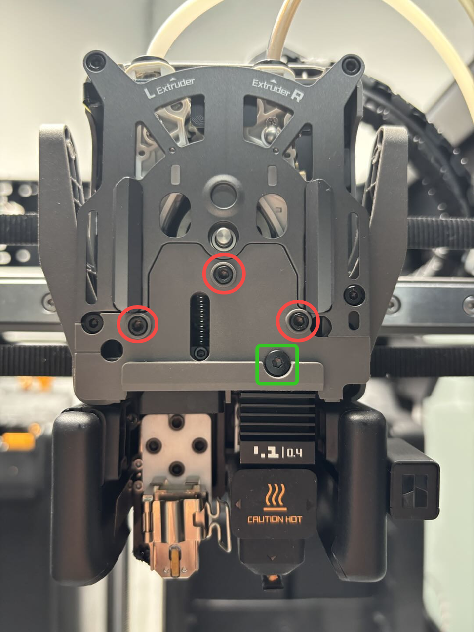 |
1 | ||
| BT2x5 | Fix the dual extruder idlers and filament sensor FPC |  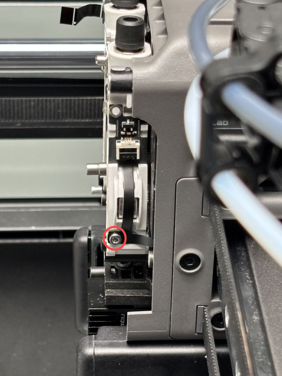 |
2 | ||
| BT3x8 | Fix the part cooling fan air duct | 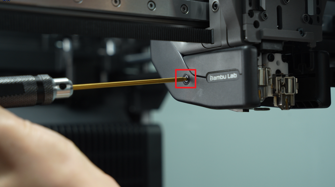 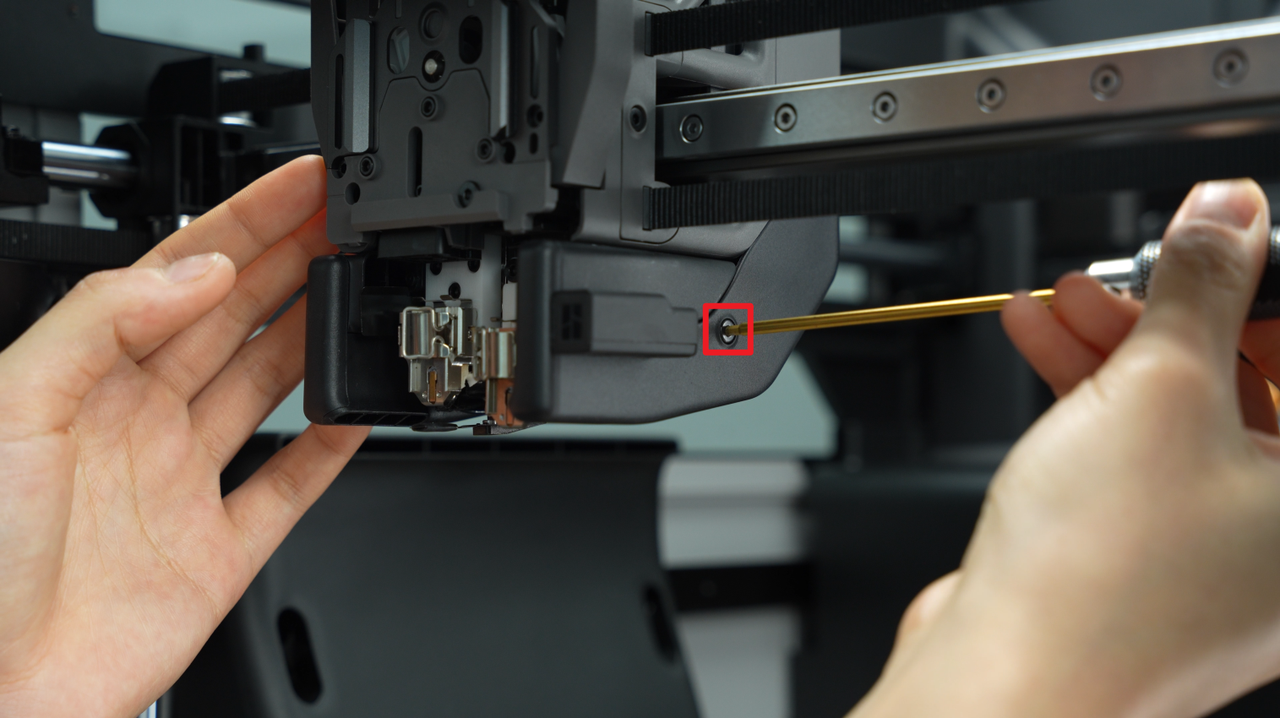  |
4 | ||
| BT3x20 | Fix the part cooling fan |  |
2 | ||
| BT2.6x8 | Fix the part cooling fan | 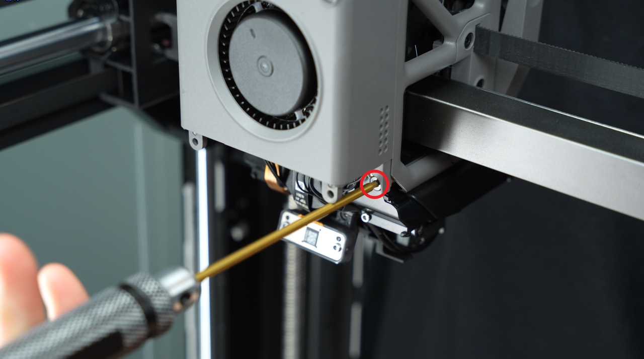 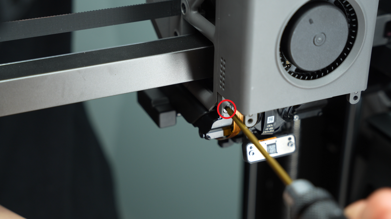 |
2 | ||
| Fix the part cooling fan |  |
2 | |||
| M2.5x8 | Fix the extruder (marked by the red circles) | 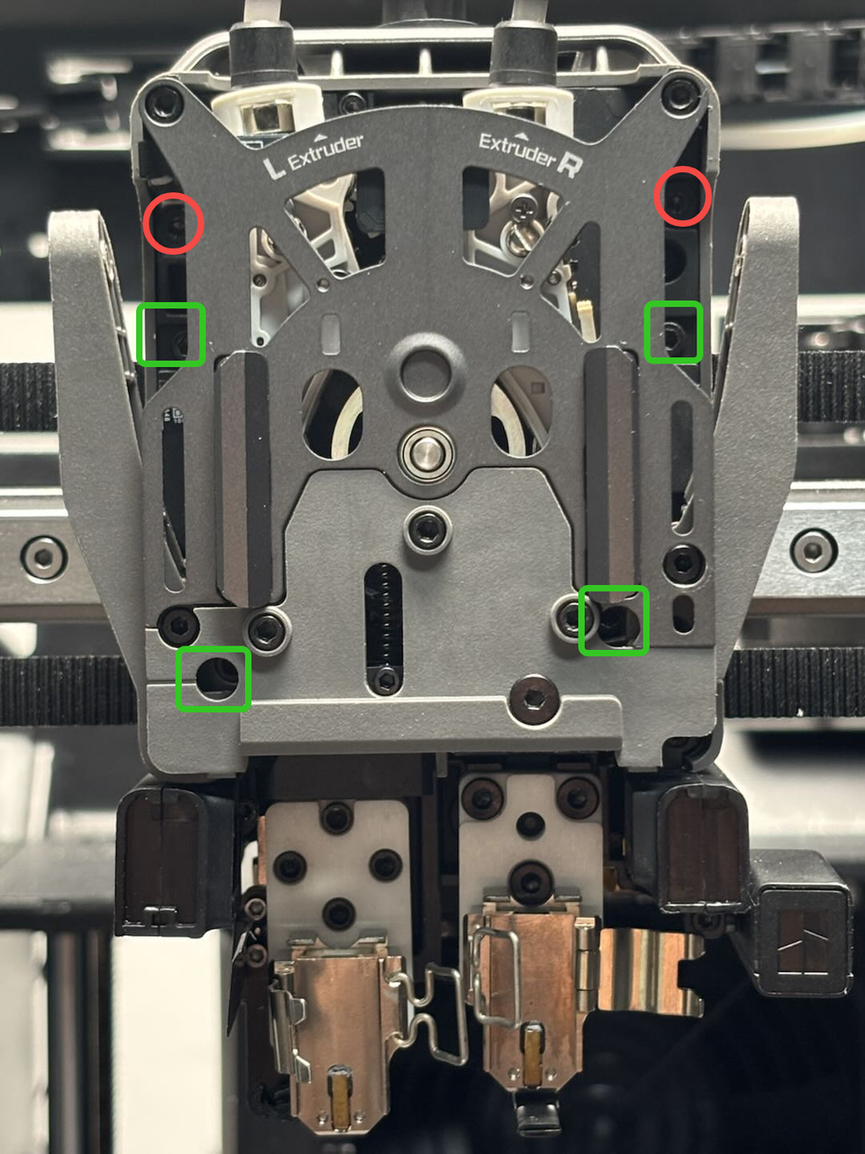 |
4 | ||
| Fix the extruder (marked by the green squares) | 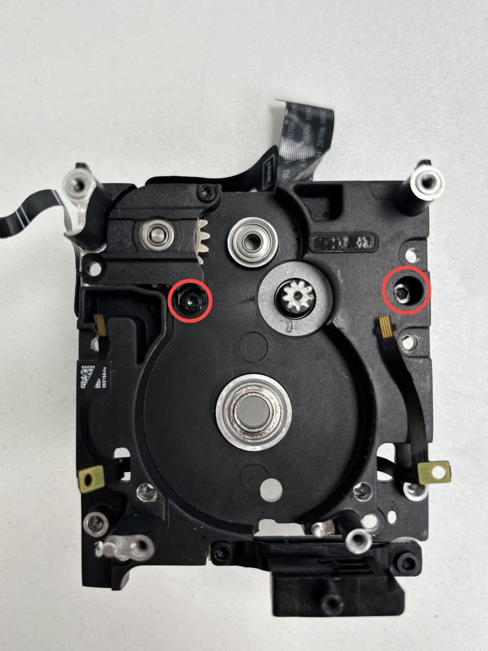 |
2 | |||
| ST2x3.5 | Fix the extruder servo motor |  |
1 |
¶ Safety Warning
IMPORTANT!
It's crucial to power off the printer before conducting any maintenance work, including work on the printer's electronics and tool head wires. Performing tasks with the printer on can result in a short circuit, leading to electronic damage and safety hazards.
During maintenance or troubleshooting, you may need to disassemble parts, including the hotend. This exposes wires and electrical components that could short circuit if they contact each other, other metal, or electronic components while the printer is still on. This can result in damage to the printer's electronics and additional issues.
Therefore, it's crucial to turn off the printer and disconnect it from the power source before conducting any maintenance. This prevents short circuits or damage to the printer's electronics, ensuring safe and effective maintenance. For any concerns or questions about following this guide, we recommend submitting a technical ticket regarding your issue and we will do our best to respond promptly and provide the assistance you need.
¶ Remove the Extruder Hall Sensor Board
¶ Step 1: Remove the extruder
You can refer to the following Wiki to remove the extruder from the toolhead:
Replace H2D Dual Extruder Unit
¶ Step 2: Remove the dual extruder idlers and filament sensor
You can refer to the following Wiki to remove the extruder idlers and filament sensor. Since the extruder has already been removed from the toolhead, you can still follow the steps in the Wiki to remove the quick change tool interface.
Replace H2D Dual Extruder Idlers and Filament Sensor
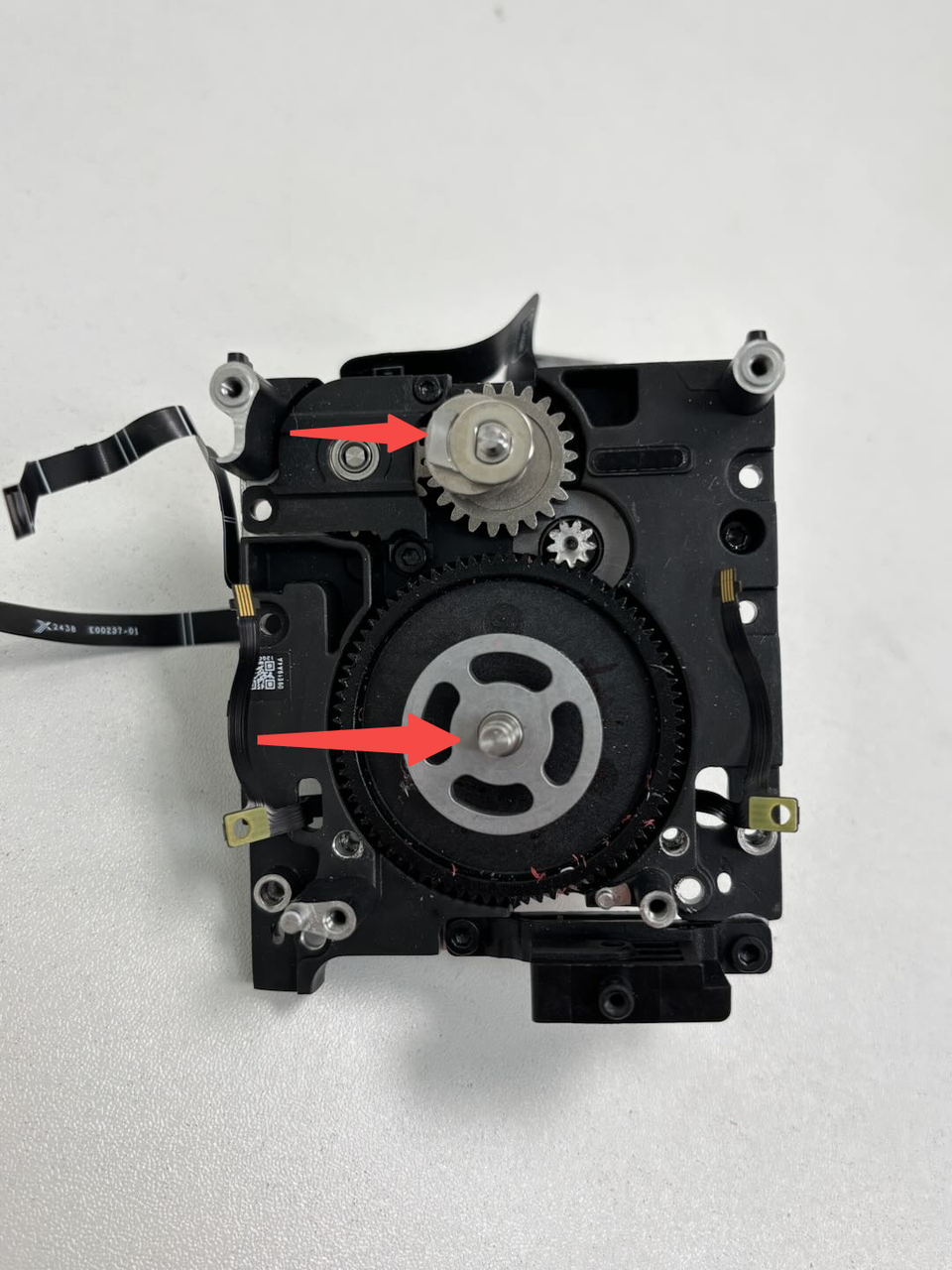
¶ Step 3: Remove the extruder gear and cam
Simply remove the cam directly. The extruder gear might be tight; if it cannot be removed directly, you can use an Allen key to gently pry and remove the extruder gear.
¶ Step 4: Remove the extruder motor
Use an H2.0 Allen key to remove 2 fixing screws (M2.5x8), then remove the extruder servo motor from the extruder rear cover.

If you need to replace the 2004 switching motor unit, since it includes the pre-installed extruder hall sensor board, you can skip the following two steps:
-
Step 5: Remove the extruder hall sensor board
-
Step 1: Install the extruder hall sensor board
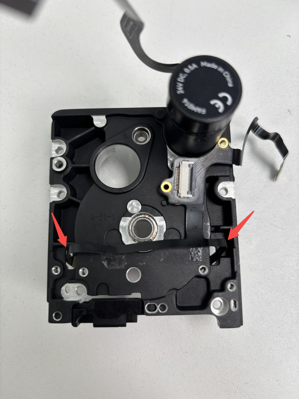
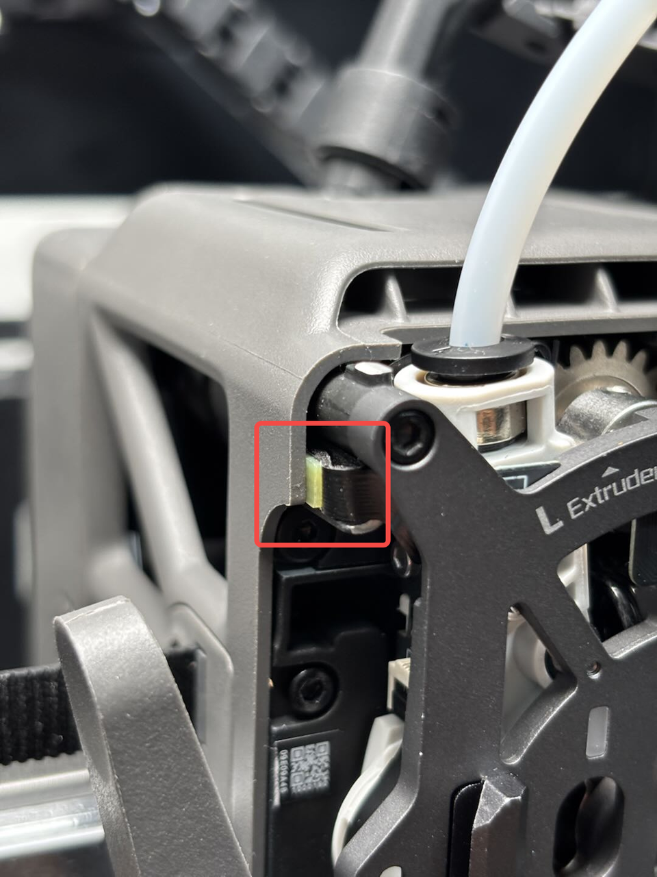
¶ Step 5: Remove the extruder hall sensor board
Unclip the FPC connector and remove the FPC, then use an H1.5 Allen key to remove one fixing screw (ST2x3.5) of the extruder hall sensor board. Peel off the FPC (attached to the extruder rear cover with adhesive) and pull the left and right FPCs out of the small holes on the extruder rear cover, then remove the extruder hall sensor board.
 |
 |
 |
¶ Install the Extruder Hall Sensor Board
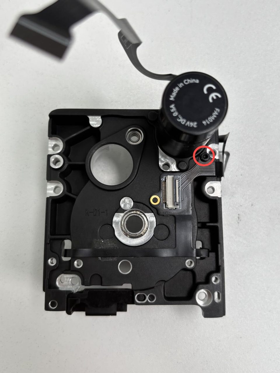
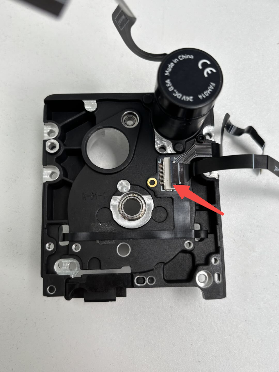
¶ Step 1: Install the extruder hall sensor board
Thread the two FPCs through the small holes on the extruder rear cover. Align the new extruder hall sensor board with the holes on the extruder rear cover and tighten one fixing screw (ST2x3.5) using an H1.5 Allen key. Attach the FPCs to the extruder rear cover as shown in the image below. Insert the FPCs into the extruder hall sensor board connector and secure the clip.
 |
 |
 |
¶ Step 2: Install the extruder servo motor
Pass the extruder servo motor shaft through the round hole on the extruder rear cover. Align the motor screw holes with the extruder rear cover, ensuring the motor cable exit is positioned upward. Tighten 2 fixing screws (M2.5x8) using an H2.0 Allen key.

¶ Step 3: Install the extruder gear and cam
Place the new cam back into position. It is recommended to position the trapezoidal platform to the left or right to facilitate the subsequent installation of the dual extruder idlers and filament sensor. Insert the new extruder gear into the extruder and press it firmly.

¶ Step 4: Install the dual extruder idlers and filament sensor
You can refer to the following Wiki to install the quick change tool interface:
Replace H2D Dual Extruder Idlers and Filament Sensor
Note: Since the extruder is not yet installed on the toolhead, you can wait to organize the Hall FPCs after installing the extruder onto the toolhead.
 |
 |
¶ Step 5: Install the extruder
You can refer to the following Wiki to install the extruder:
Replace H2D Dual Extruder Unit
¶ Verify the Functionality
Connect the power supply and turn on the printer, initiate printing, and confirm whether it can print successfully.
¶ End Notes
We hope the detailed guide provided has been helpful and informative.
If this guide does not solve your problem, please submit a technical ticket, we will answer your questions and provide assistance.
If you have any suggestions or feedback on this Wiki, please leave a message in the comment area. Thank you for your support and attention!