¶ Extruder Servo Motor
The extruder servo motor is installed on the back of the extruder and is used to drive the extruder, enabling the extrusion of the filament.
The spare parts for the Extruder Servo Motor include:
-
2004 Extruder Servo Motor * 1
-
M2.5x8 Screws (used to fix the extruder servo motor) * 2
¶ When to Use
- The extruder servo motor is damaged.
¶ Tools and materials needed
-
New quick change tool interface
-
H2.0 Allen key
-
H1.5 Allen key
-
Tweezers
Specifications and quantities of screws involved in replacing the H2D extruder servo motor (it is recommended to keep the removed screws properly to avoid loss):
| Specification | Image | Use | Position | Quantity | |
|---|---|---|---|---|---|
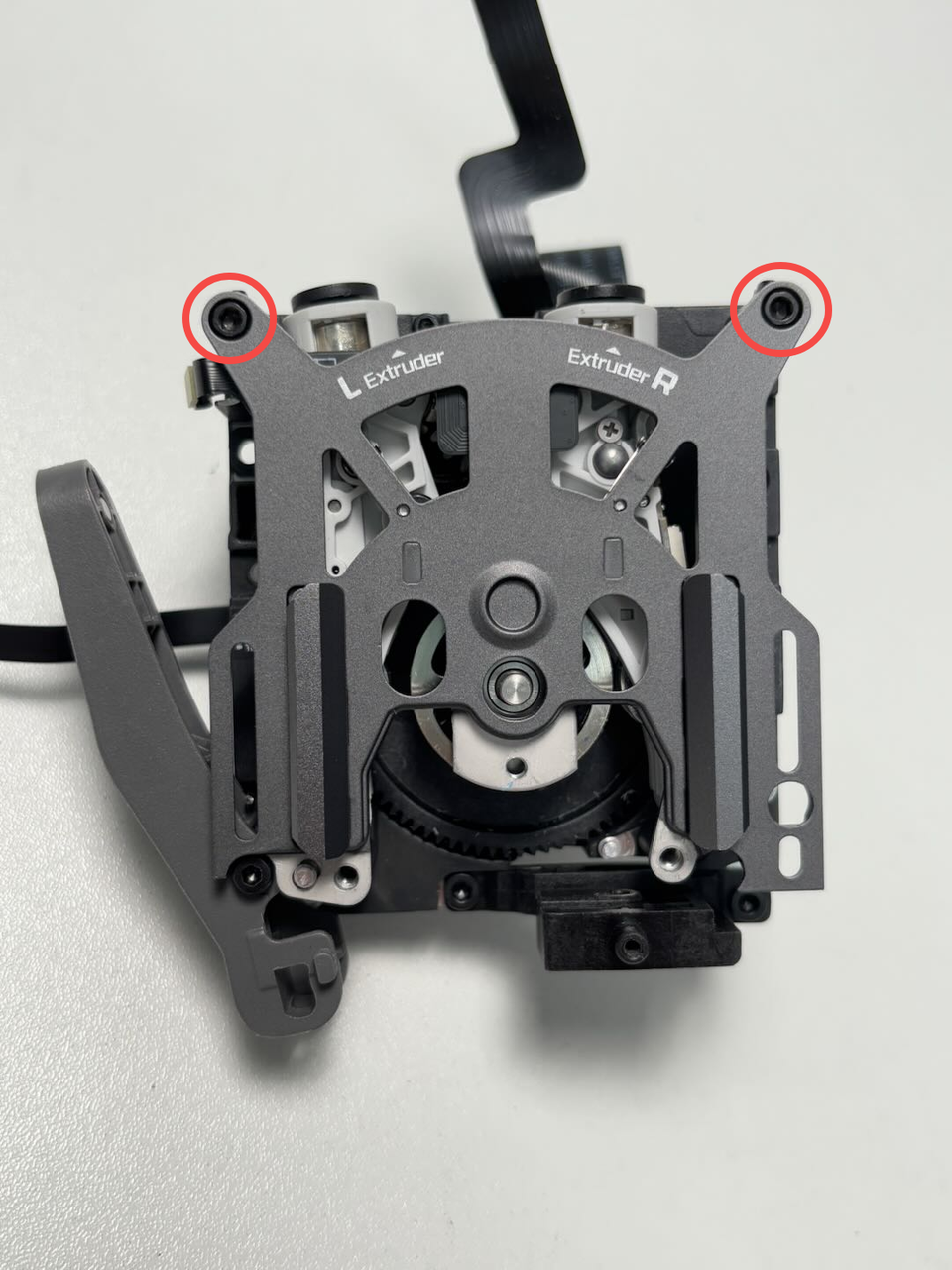
| M2.5x7 | Fix the dual extruder filament guide (marked by the red circles) |  |
3 | ||
| Fix the quick change tool interface | 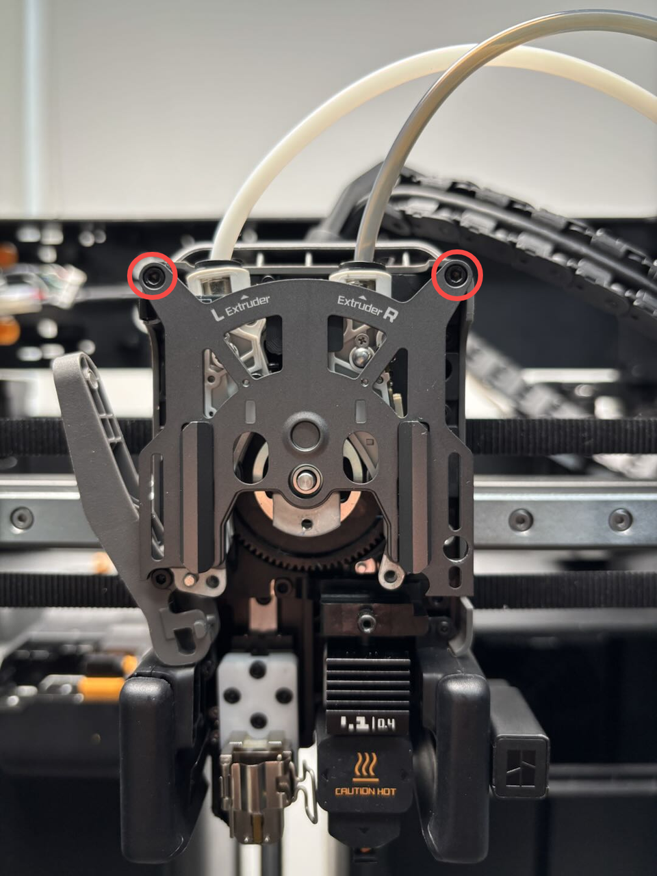 |
2 | |||
| BT2x6 | Fix the dual extruder filament guide (marked by the green squares) | 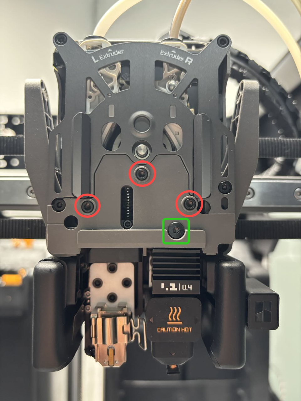 |
1 | ||
| BT2x5 | Fix the dual extruder idlers and filament sensor FPC | 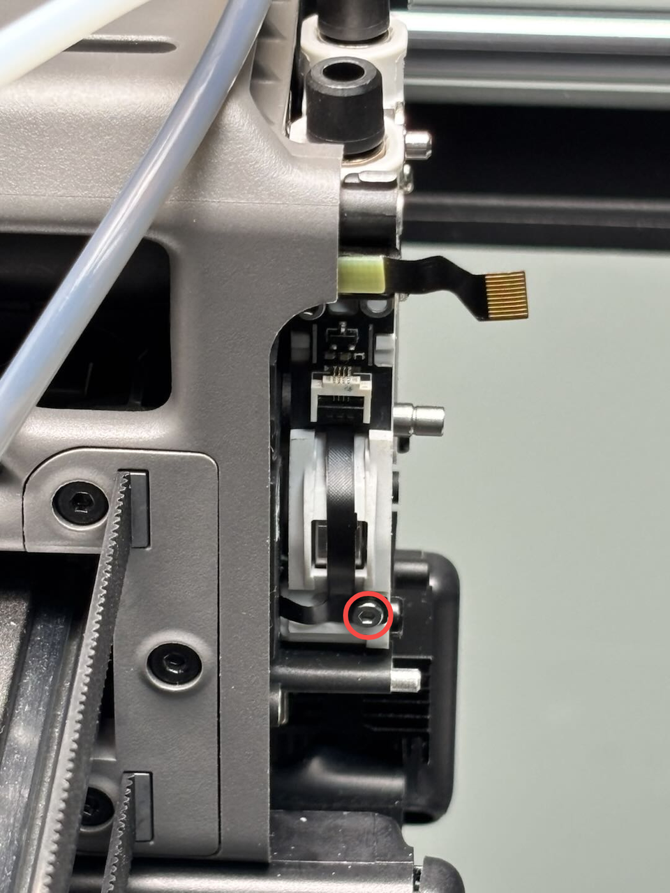 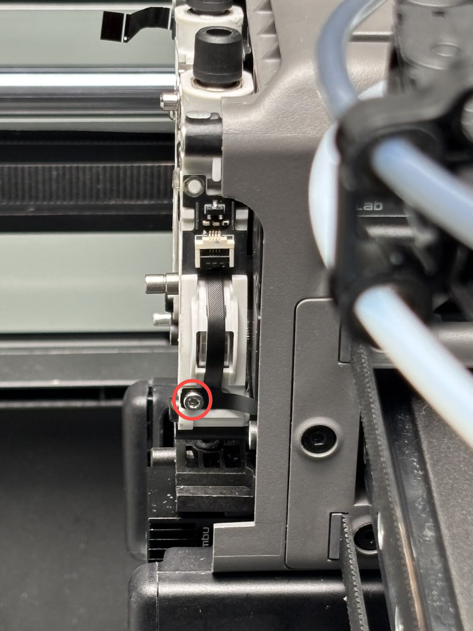 |
2 | ||
| BT3x8 | Fix the part cooling fan air duct | 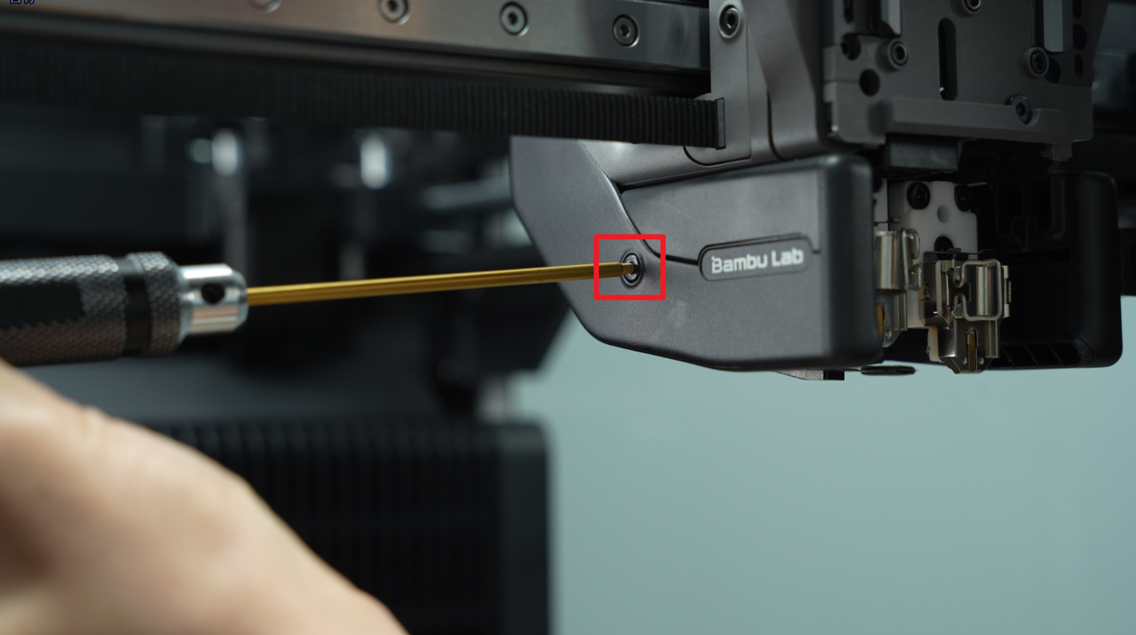 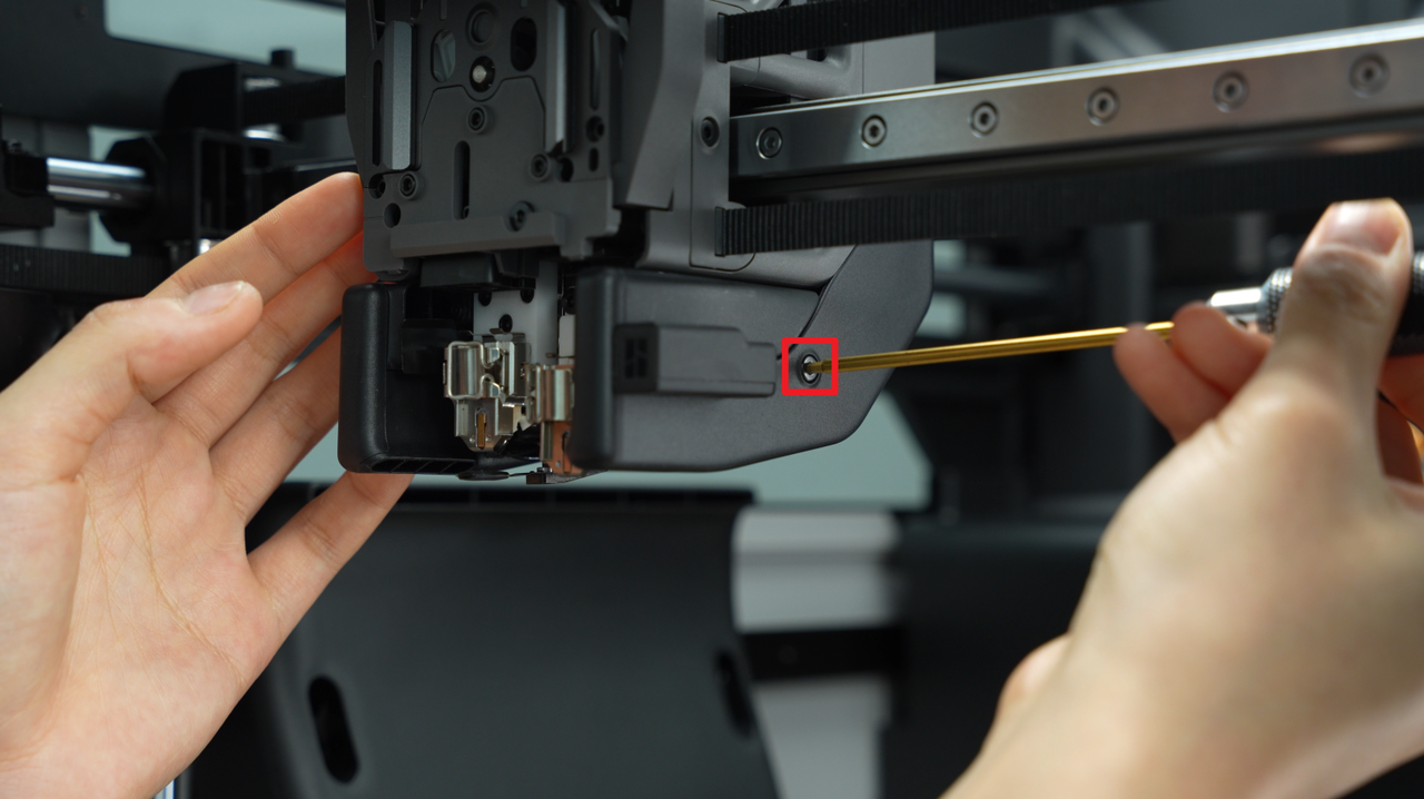 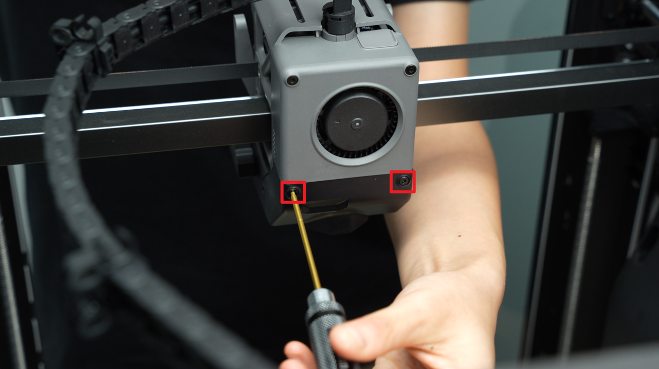 |
4 | ||
| BT3x20 | Fix the part cooling fan | 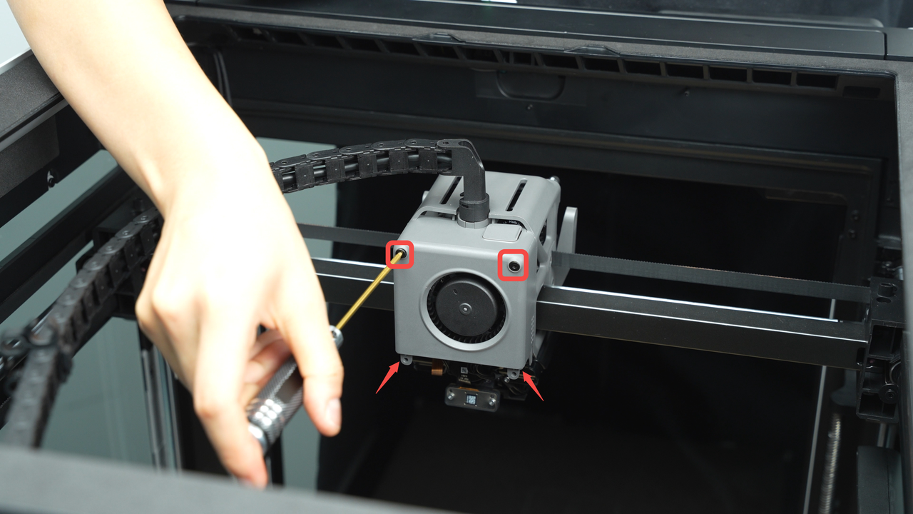 |
2 | ||
| BT2.6x8 | Fix the part cooling fan | 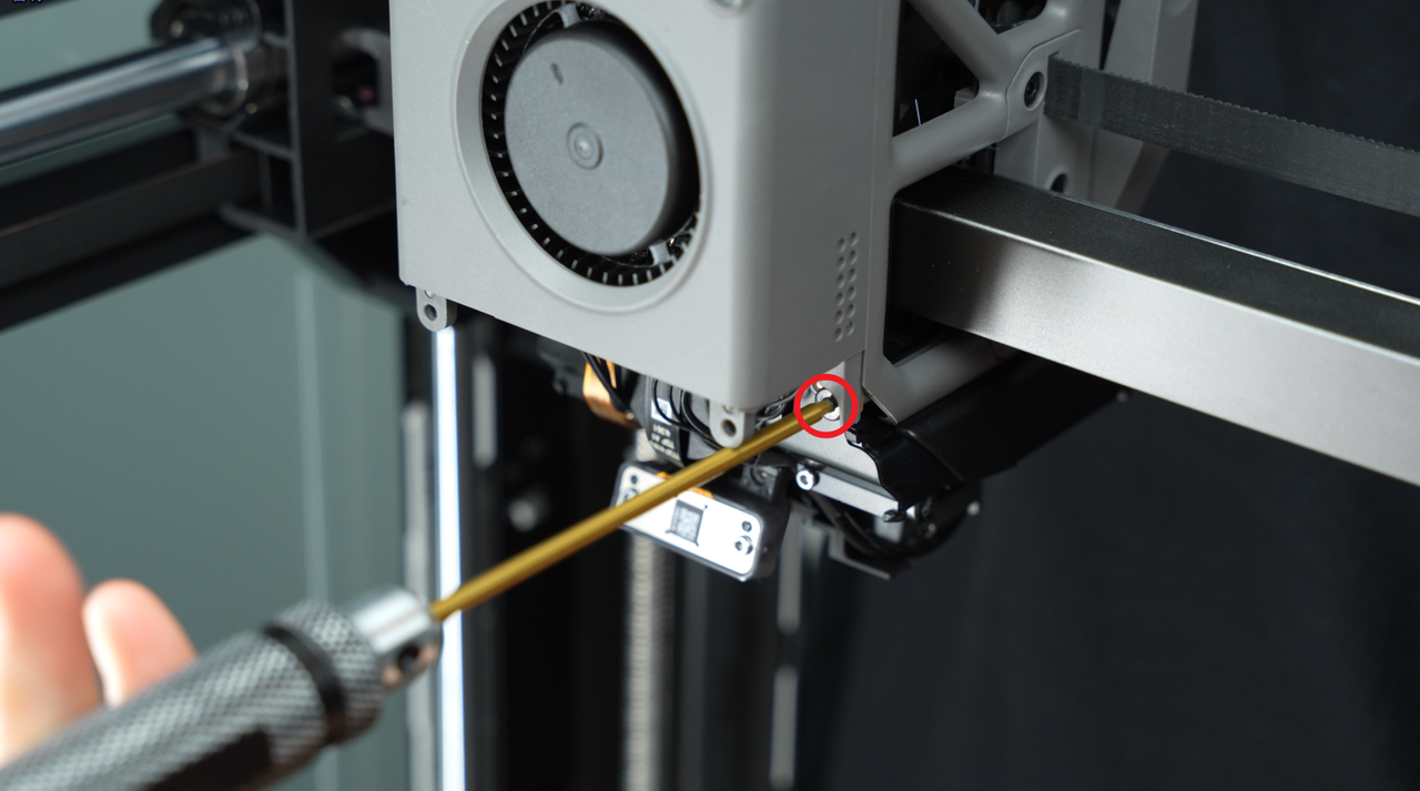 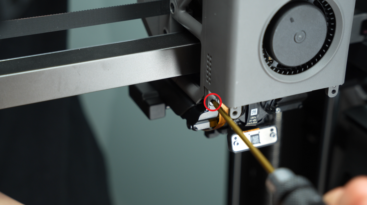 |
2 | ||
| Fix the extruder (marked by the red circles) | 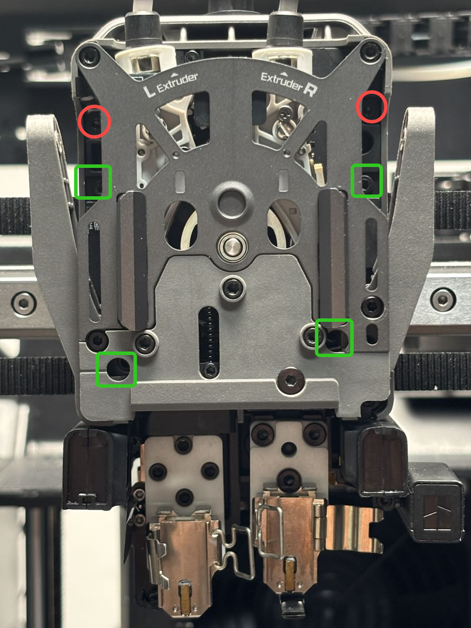 |
2 | |||
| M2.5x8 | Fix the extruder (marked by the green squares) |  |
4 | ||
| Fix the extruder servo motor | 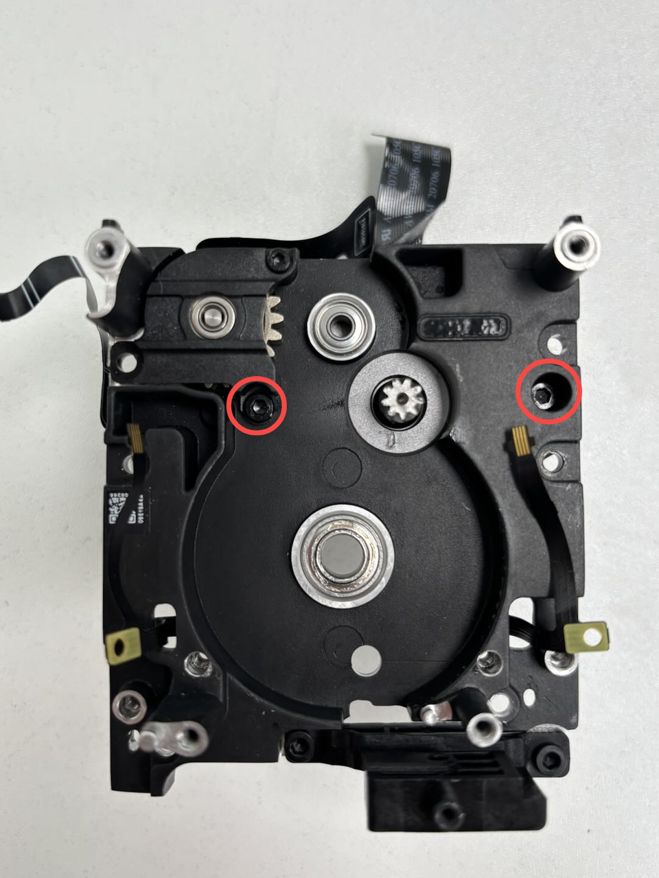 |
2 |
¶ Safety Warning
IMPORTANT!
It's crucial to power off the printer before conducting any maintenance work, including work on the printer's electronics and tool head wires. Performing tasks with the printer on can result in a short circuit, leading to electronic damage and safety hazards.
During maintenance or troubleshooting, you may need to disassemble parts, including the hotend. This exposes wires and electrical components that could short circuit if they contact each other, other metal, or electronic components while the printer is still on. This can result in damage to the printer's electronics and additional issues.
Therefore, it's crucial to turn off the printer and disconnect it from the power source before conducting any maintenance. This prevents short circuits or damage to the printer's electronics, ensuring safe and effective maintenance. For any concerns or questions about following this guide, we recommend submitting a technical ticket regarding your issue and we will do our best to respond promptly and provide the assistance you need.
¶ Remove the 3513 Extruder Servo Motor
¶ Step 1: Remove the extruder servo motor
You can refer to this Wiki to remove the extruder from the toolhead to facilitate the subsequent removal of the 3513 extruder servo motor:
Replace H2D Dual Extruder Unit
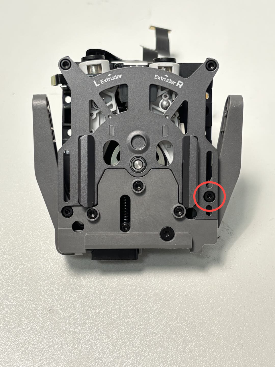
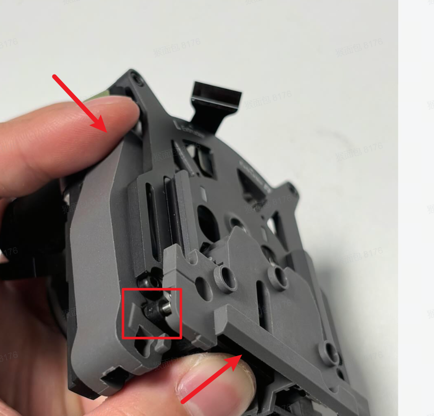
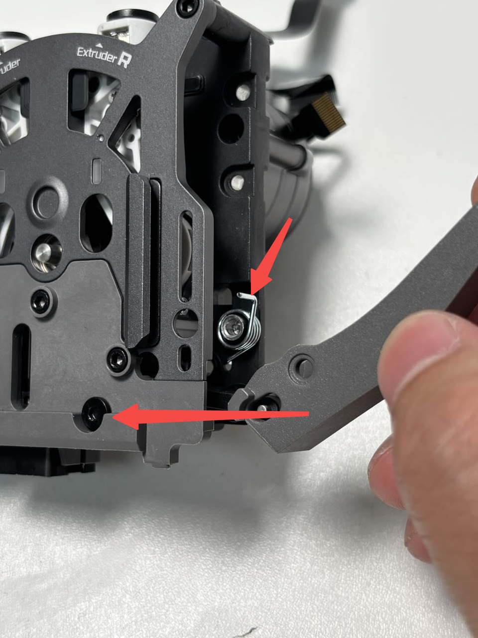
¶ Step 2: Remove the right filament cutter
Place the extruder on the table. Use an H2.0 Allen key to remove one fixing screw from the right cutter lever, then detach the right cutter lever and torsion spring from the extruder.

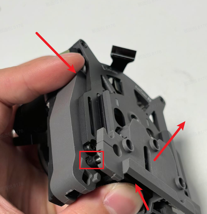
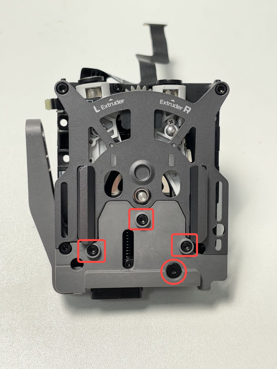
¶ Step 3: Remove the dual extruder filament guide
Use an H2.0 Allen key to remove 4 fixing screws (marked with squares: M2.5x7 * 3; marked with a circle: BT2x6 * 1). Hold the left cutter and the slider at the bottom of the dual extruder filament guide (to align the cutter with the notch on the cutter lever), then pull the dual extruder filament guide forward to remove it.

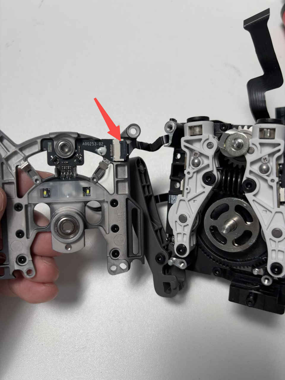
¶ Step 4: Remove the quick change tool interface
Use an H2.0 Allen key to remove 2 fixing screws (M2.5x7 * 2). Gently wiggle and remove the quick change tool interface, then disconnect the hall connector.
Note: Carefully remove the quick change tool interface to avoid damaging the cables!


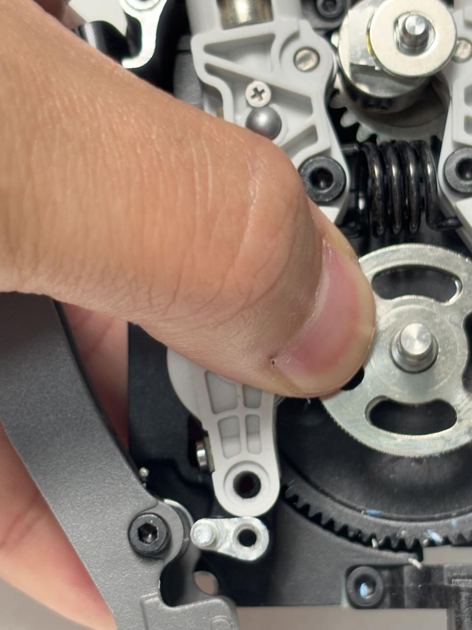
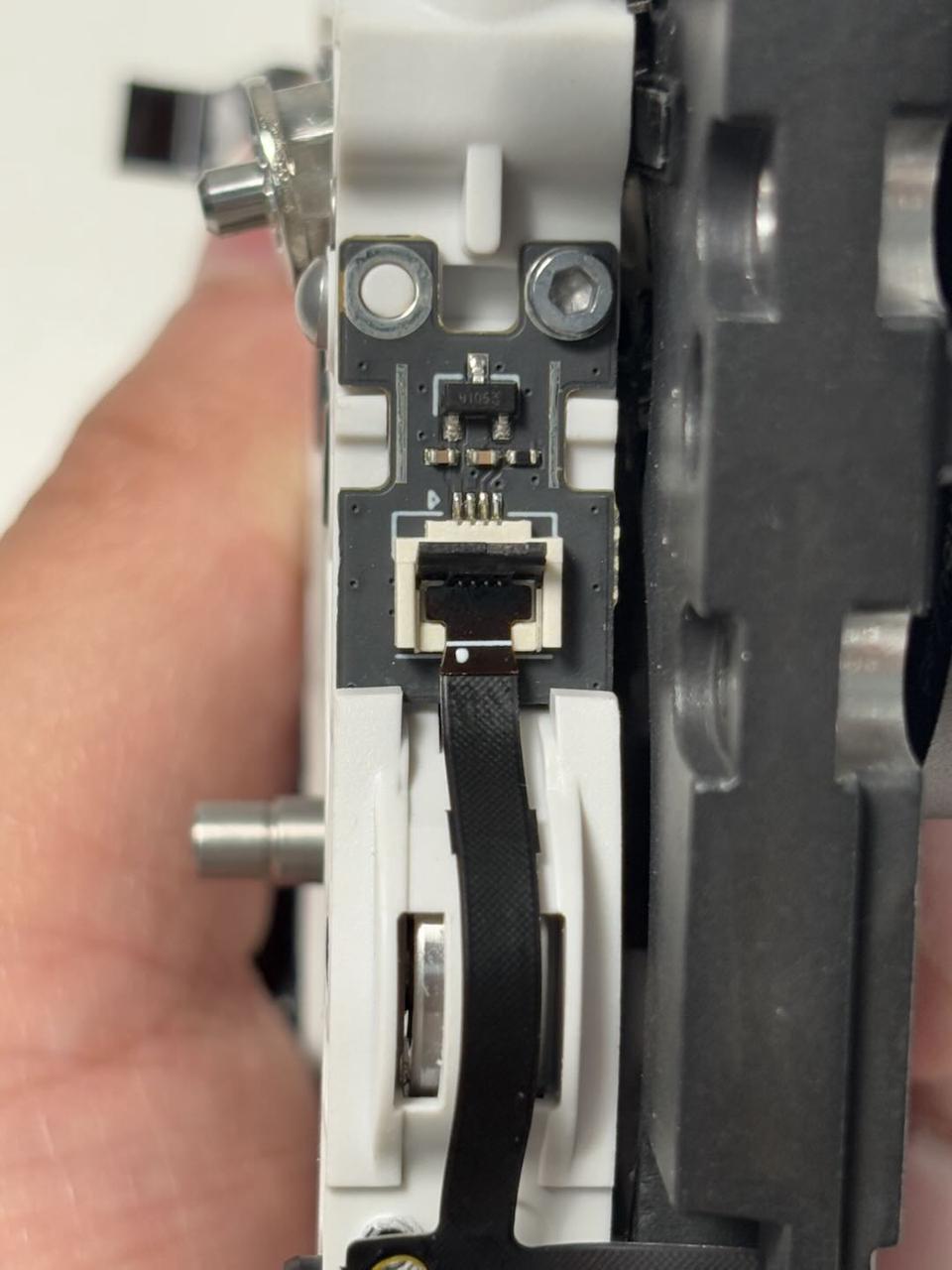
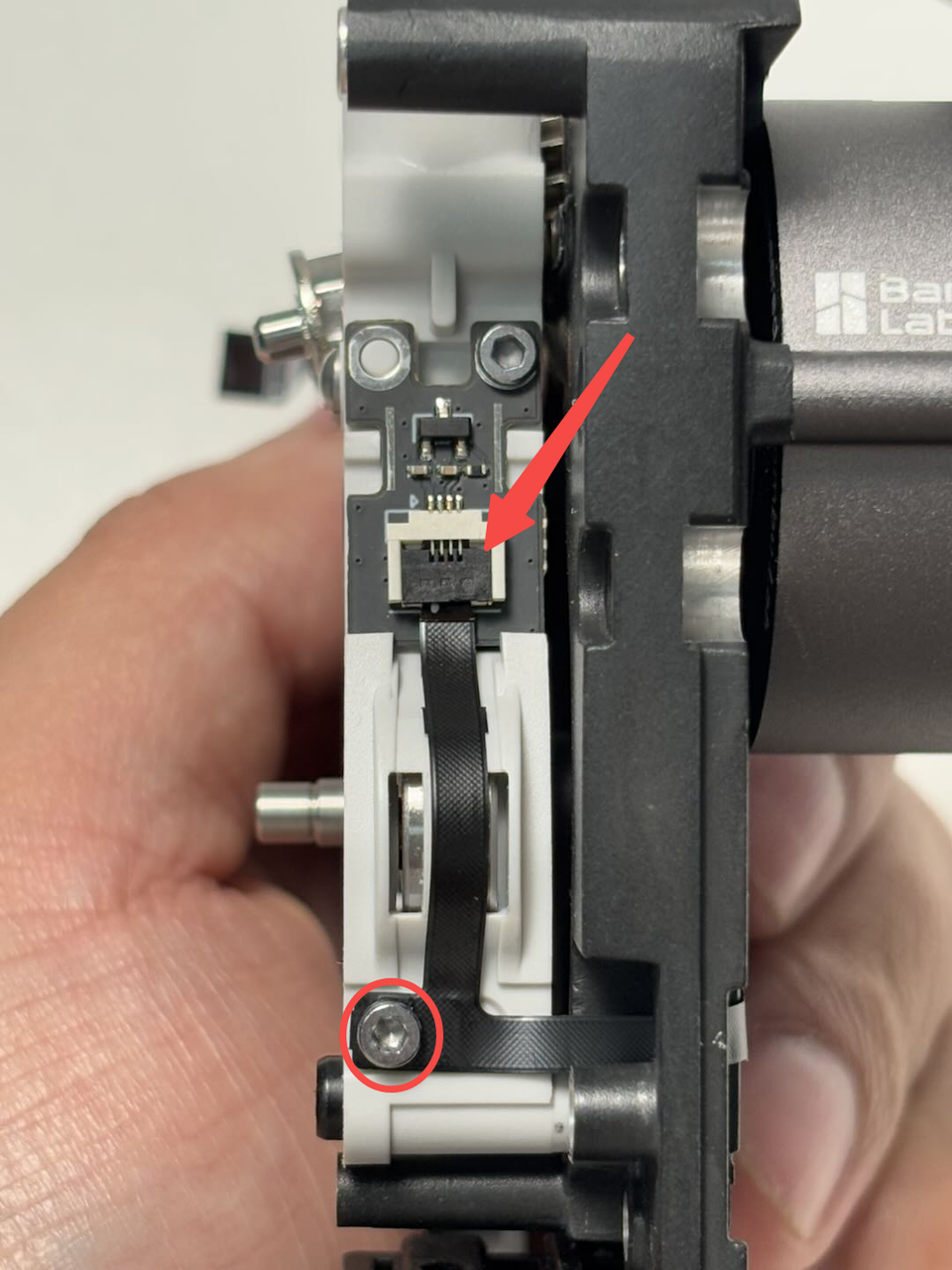
¶ Step 5: Remove the dual extruder idlers and filament sensor
- Use an H1.5 Allen key to remove the hall FPC fixing screw (BT2x5 * 1) on the right side of the dual extruder idlers and filament sensor, then disconnect the right Hall FPC.
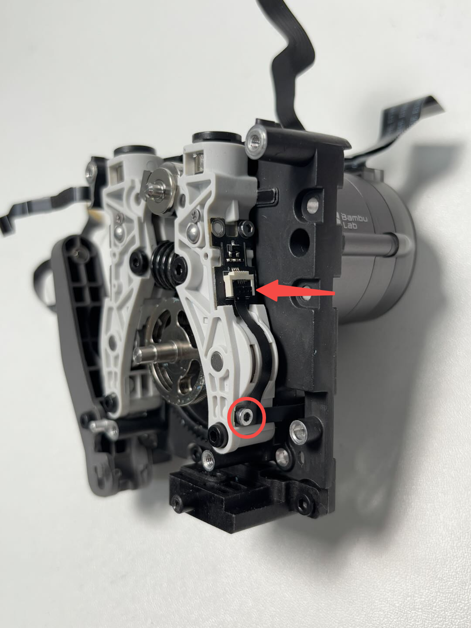
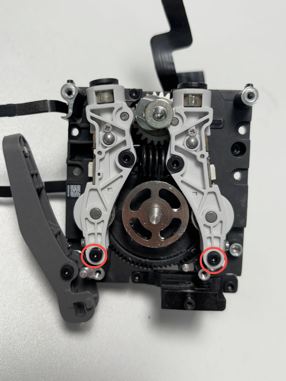
- Use an H2.0 Allen key to remove 2 fixing screws (M2.5x19x5), take out the dual extruder idlers, and flip it to the left side to facilitate the removal of the extruder servo motor fixing screws.
Note:
Do not remove the left Hall FPC.
Be careful when flipping to avoid damaging the left Hall FPC.

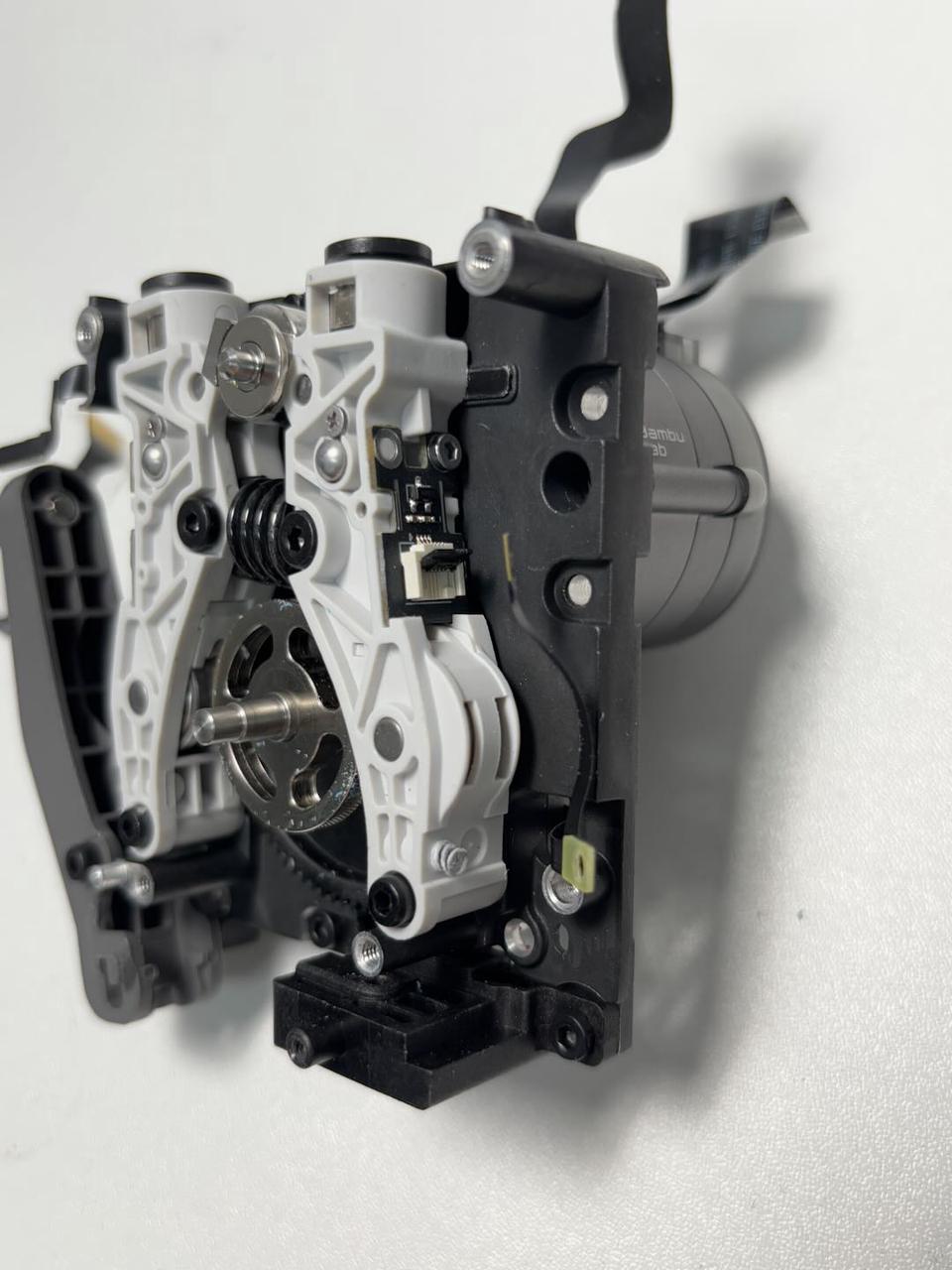
¶ Step 6: Remove the extruder servo motor
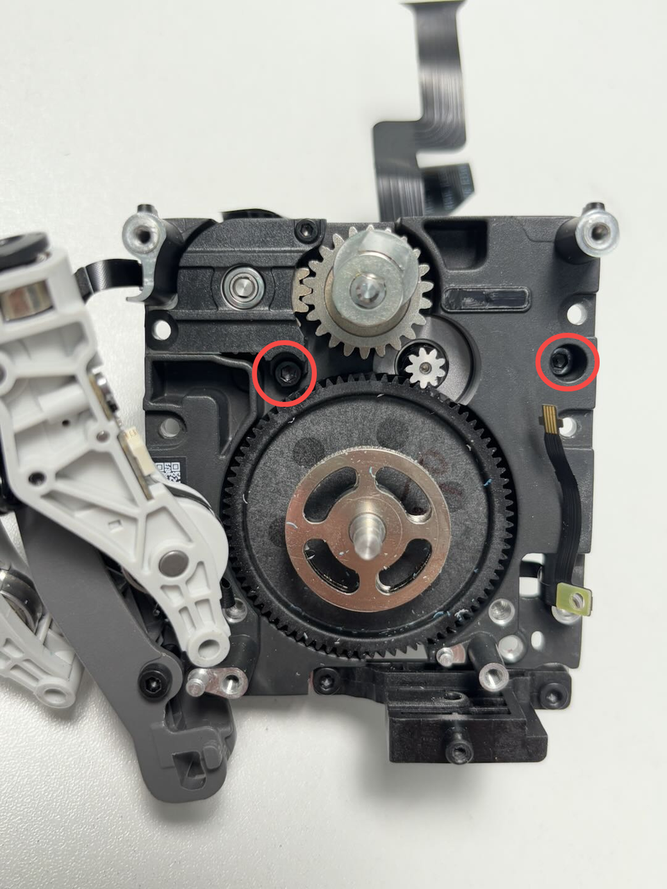
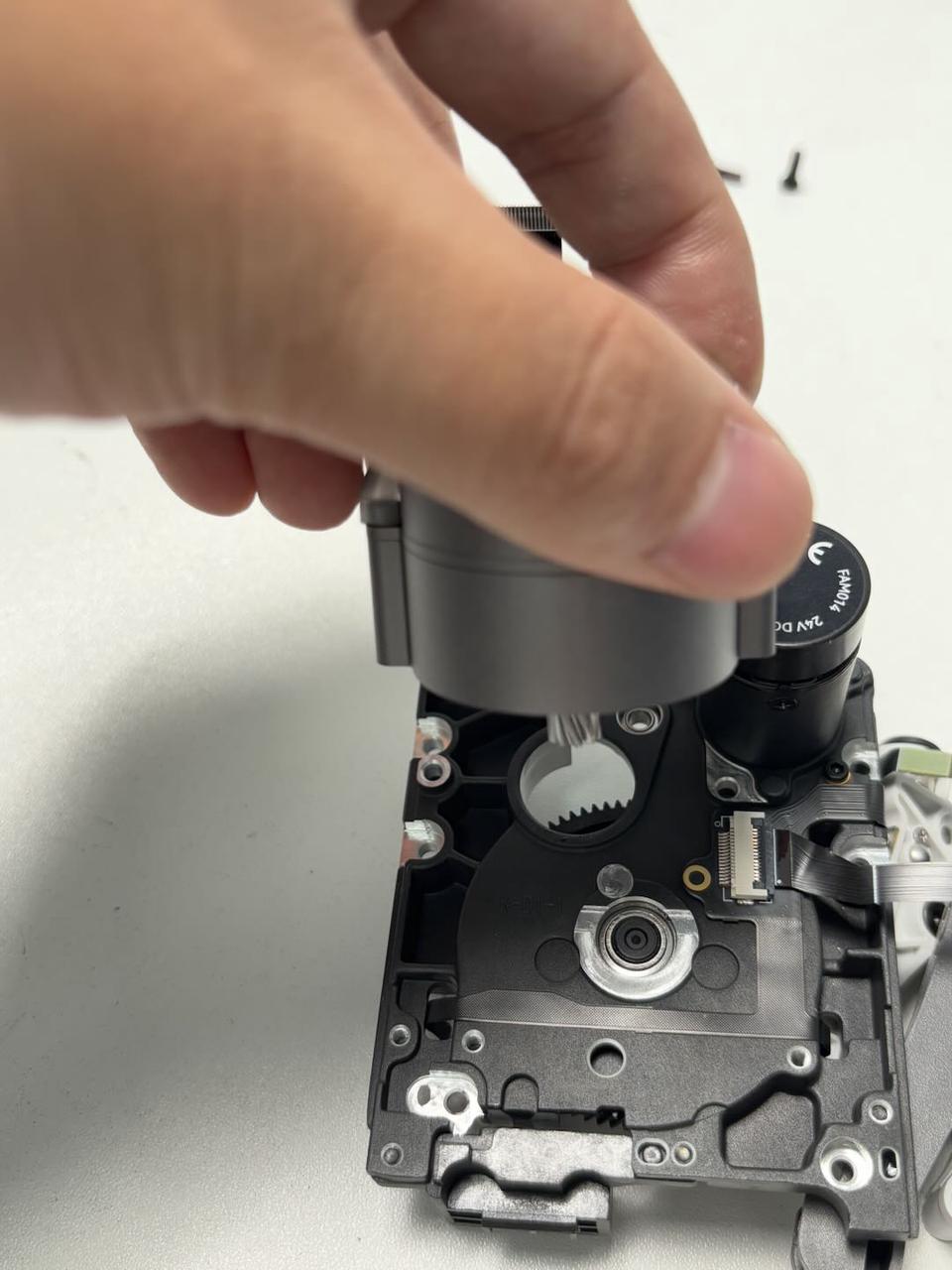
Use an H2.0 Allen key to remove 2 fixing screws (M2.5x8) of the 3513 extruder servo motor, then remove the extruder servo motor from the dual extruder unit.
¶ Install the 3513 Extruder Servo Motor
¶ Step 1: Install the 3513 extruder servo motor
Align the new extruder servo motor with the holes on the extruder rear cover, then tighten 2 fixing screws using an H2.0 Allen key.
Note: When flipping the extruder rear cover, support the dual extruder gears and cam or remove them in advance to prevent them from falling.

¶ Step 2: Install the dual extruder idlers and filament sensor
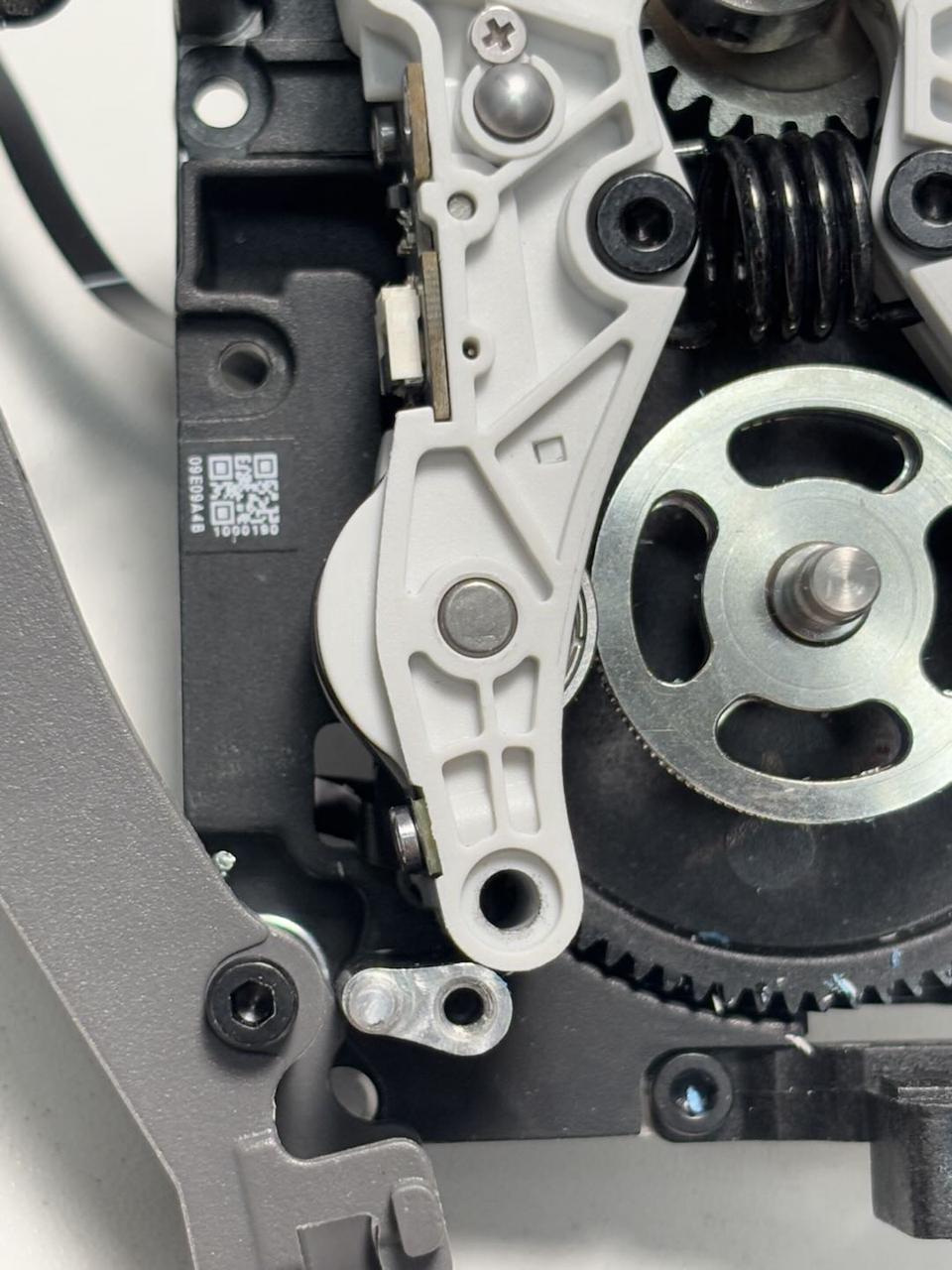
- Reattach the dual extruder idlers and filament sensor to the extruder. Manually push the driven rod to align the screw hole at the bottom of the driven rod with the extruder rear cover, then tighten 2 fixing screws using an H2.0 Allen key.

- Insert the right Hall FPC into the extruder idler, secure the clip, and tighten one Hall FPC fixing screw (BT2x5) using an H1.5 Allen key.
¶ Step 3: Install the quick change tool interface
Connect the Hall FPC to the quick change tool interface, then attach the quick change tool interface to the extruder. Tighten two fixing screws using an H2.0 Allen key.
¶ Step 4: Install the dual extruder filament guide
Hold the left cutter lever and the slider at the bottom of the dual extruder filament guide simultaneously (to align the cutter with the notch on the cutter lever), then insert the dual extruder filament guide into the extruder. Tighten 4 fixing screws using an H2.0 Allen key.
¶ Step 5: Install the right cutter
Insert the torsion spring into the extruder, then insert the cutter and cutter lever together into the extruder. Tighten one fixing screw using an H2.0 Allen key.

¶ Step 6: Install the dual extruder unit
You can refer to this Wiki to reinstall the dual extruder unit onto the toolhead:
Replace H2D Dual Extruder Unit
¶ Verify the Functionality
Connect the power and turn on the printer. Initiate a print job and check if it completes successfully.
¶ End Notes
We hope the detailed guide provided has been helpful and informative.
If this guide does not solve your problem, please submit a technical ticket, we will answer your questions and provide assistance.
If you have any suggestions or feedback on this Wiki, please leave a message in the comment area. Thank you for your support and attention!