¶ Hall Effect Sensor
.png)
On the H2D printer, there are two types of hall effect sensor: digital hall effect sensor and analog hall effect sensor.
- Digital Hall Effect Sensor:
These are square-shaped. There are a total of 3 digital hall effect sensors on the printer:
-
Automatic Top Vent Detection Hall Effect Sensor: Located below the automatic top vent, it is fixed to the upper frame cover using one screw (BT2x5). It is used to detect the opening and closing of the automatic top vent.
-
Emergency Stop Button Detection Hall Effect Sensor *2: Located on the bottom side of the printer, there are two hall effect sensors installed together. Each is fixed using one screw (M2x2.5). These are used to detect the emergency stop button.
- Analog Hall Effect Sensor:
These are rectangular-shaped. There are a total of 8 analog hall effect sensors on the printer:
-
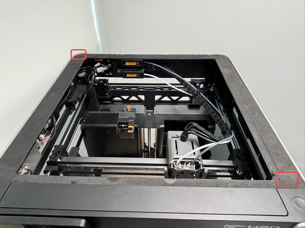
Glass Cover Plate/Acrylic Board Detection Hall Effect Sensor *2: Located on the top surface of the enclosure top frame, the two hall effect sensors are positioned at the rear left and front right of the top cover. Both are fixed using one screw (BT2x5). They are used to detect whether the glass cover plate/acrylic board is placed on the printer.
-
Left Side Glass Detection Hall Effect Sensor (Upper): Located on the outer rear side of the top frame left section, it is fixed using one screw (M2x2.5). It is used to detect whether the left side glass is properly installed.
-
Left Side Glass Detection Hall Effect Sensor (Lower): Located on the inner side of the left panel. It is used to detect whether the left side panel is properly installed.
-
Right Side Glass Detection Hall Effect Sensor (Upper): Located on the inner front side of the top frame right section, it is fixed using one screw (BT2x5). It is used to detect whether the right side glass is properly installed.
-
Right Side Glass Detection Hall Effect Sensor (Lower): Located on the inner side of the right panel. It is used to detect whether the right side glass is properly installed.
-
Front Door Glass/Acrylic Board Detection Hall Effect Sensor *2: Located on the inner side of the front right pillar, the two hall effect sensors are positioned at the upper and lower positions. Both are fixed using one screw (M2x2.5). They are used to detect whether the front door glass/acrylic board is closed.
The following list details the spare parts for the hall effect sensor. You may select the appropriate hall effect sensor for replacement based on actual conditions. Unused hall effect sensors and screws can be kept as spares.
-
Digital hall effect sensor *1
-
Analog hall effect sensor *1
-
BT2x5 screw *1
-
M2x2.5 screw *1
-
Upper frame cover foam - Can be used for destructive removal of foam when replacing glass cover plate/acrylic board to detect hall effect sensor.
¶ When to use
-
When the hall effect sensor is visibly damaged;
-
When the hall effect sensor is malfunctioning and needs to be replaced as advised by Bambu Lab technical support;
¶ Tools and Materials Needed
-
New hall effect sensor
-
H1.5 Allen key
-
H2.0 Allen key
-
Tweezers
¶ Safety Warning
IMPORTANT!
It's crucial to power off the printer before conducting any maintenance work, including work on the printer's electronics and tool head wires. Performing tasks with the printer on can result in a short circuit, leading to electronic damage and safety hazards.
During maintenance or troubleshooting, you may need to disassemble parts, including the hotend. This exposes wires and electrical components that could short circuit if they contact each other, other metal, or electronic components while the printer is still on. This can result in damage to the printer's electronics and additional issues.
Therefore, it's crucial to turn off the printer and disconnect it from the power source before conducting any maintenance. This prevents short circuits or damage to the printer's electronics, ensuring safe and effective maintenance. For any concerns or questions about following this guide, we recommend submitting a technical ticket regarding your issue and we will do our best to respond promptly and provide the assistance you need.
¶ Automatic Top Vent Detection Hall Effect Sensor
¶ Remove the Automatic Top Vent Detection Hall Effect Sensor
¶ Step 1: Remove the front cover
You can remove the screen and front cover together; there is no need to separate the screen from the front cover. For detailed steps, please refer to the following Wiki:
¶ Step 2: Remove the hall effect sensor
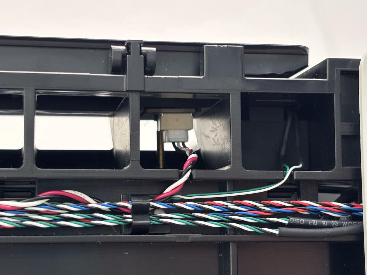
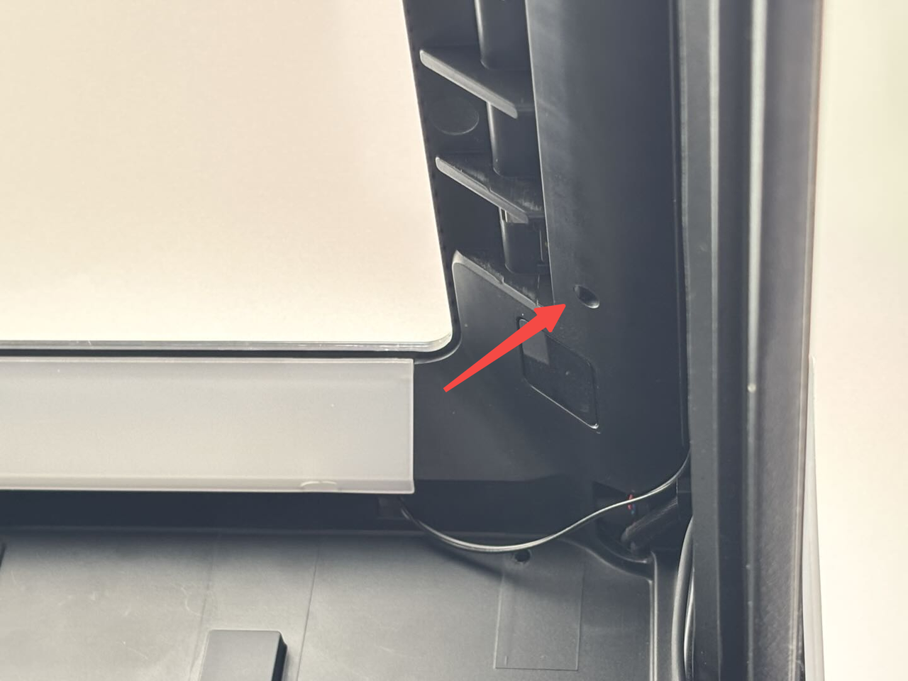
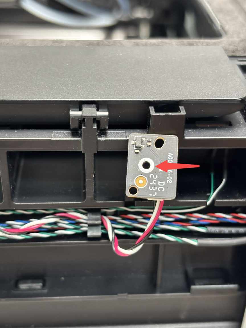
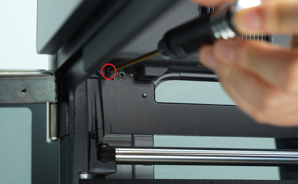
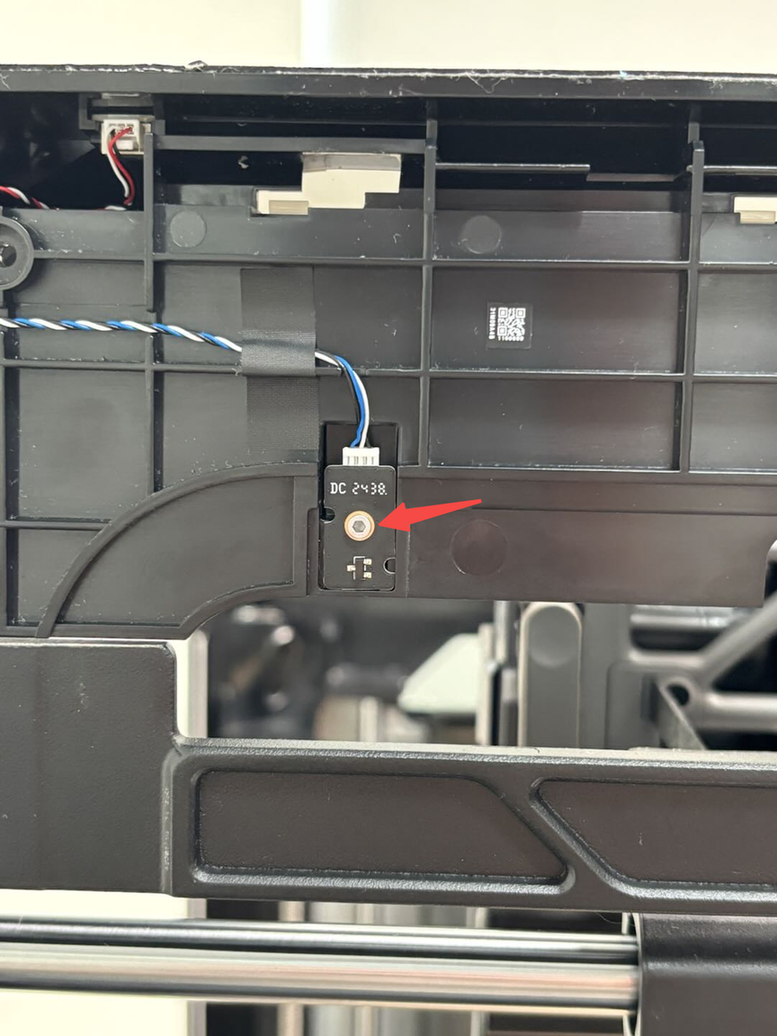
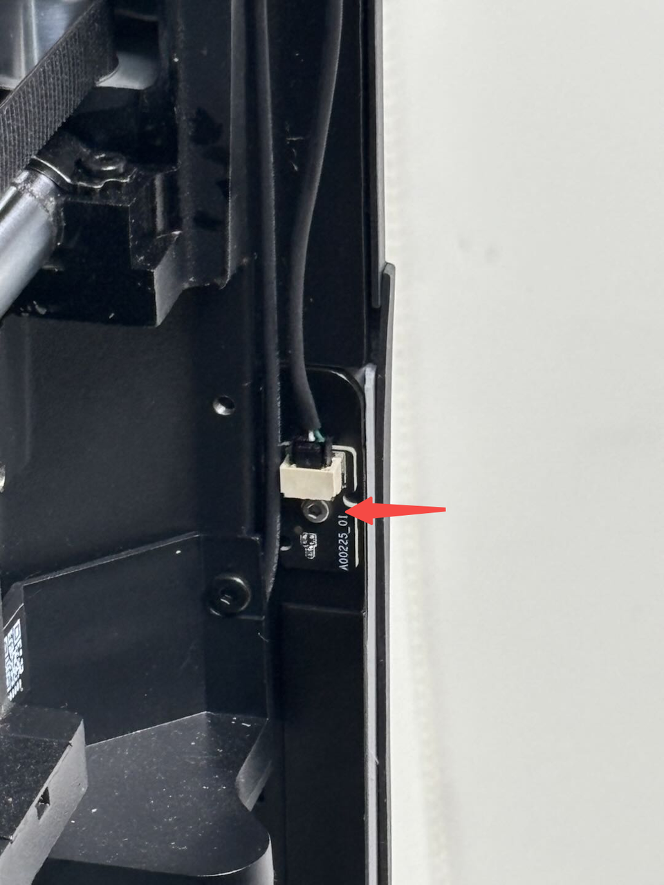
- Refer to the image below to locate the hall effect sensor. Use a H1.5 Allen key to access the small hole at the bottom of the upper cover and remove one hall effect sensor fixing screw (BT2x5).
It is recommended to place the screw in a box to avoid losing it.

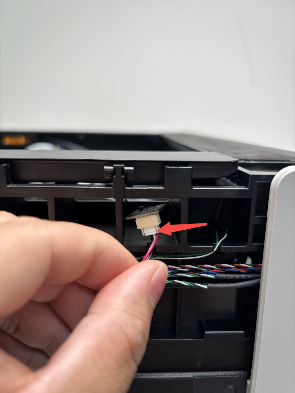
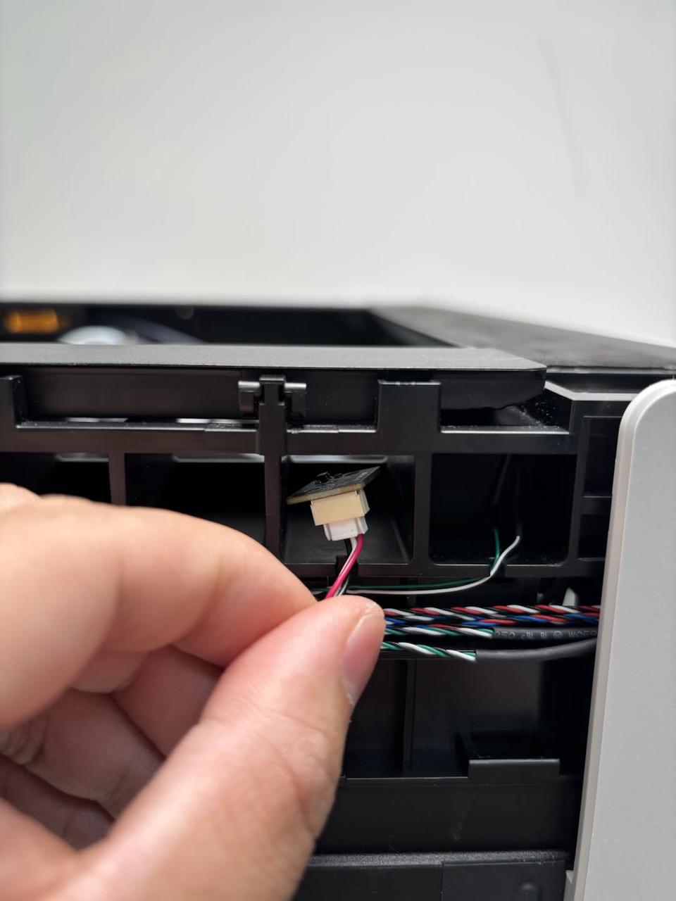
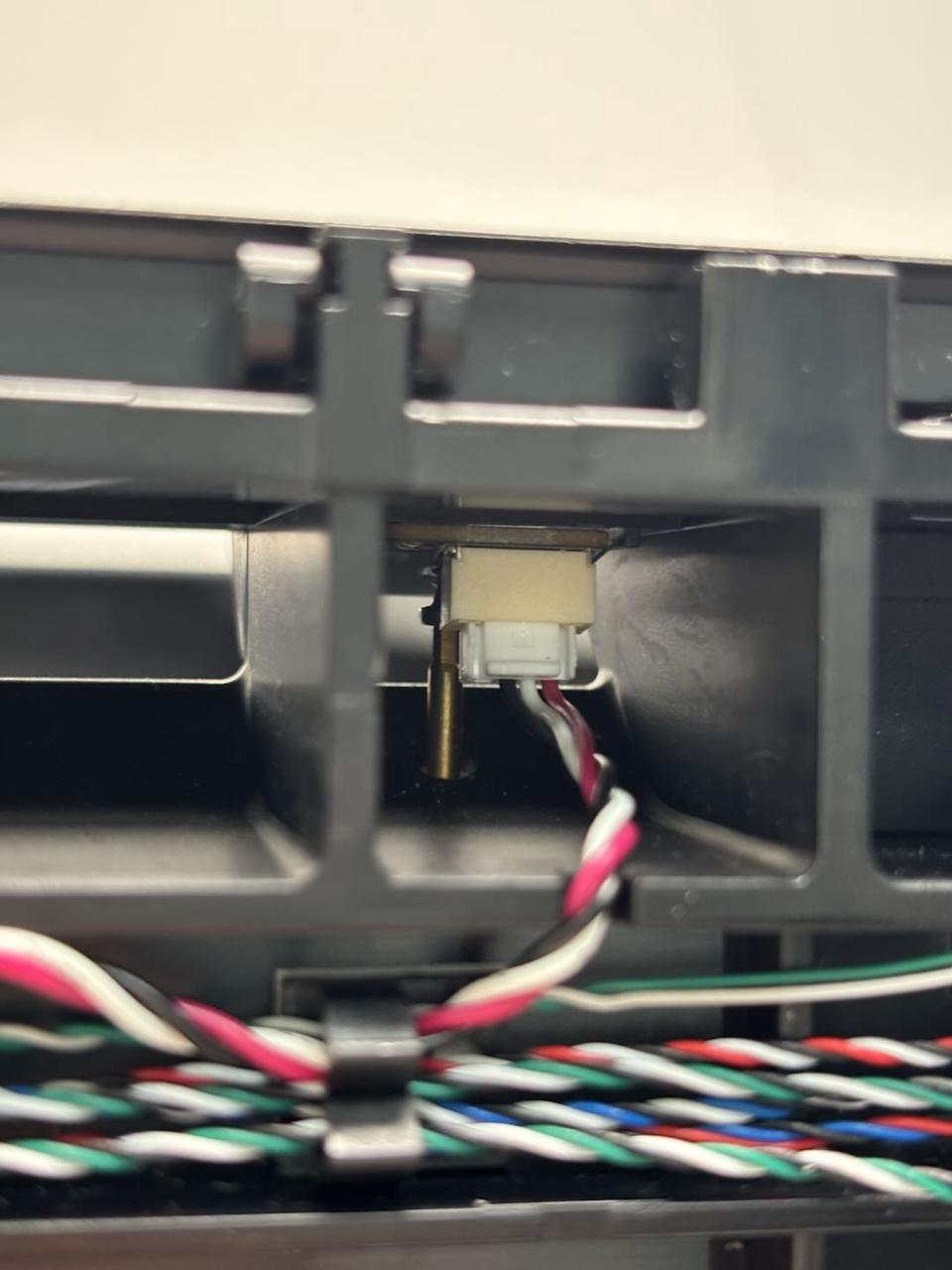
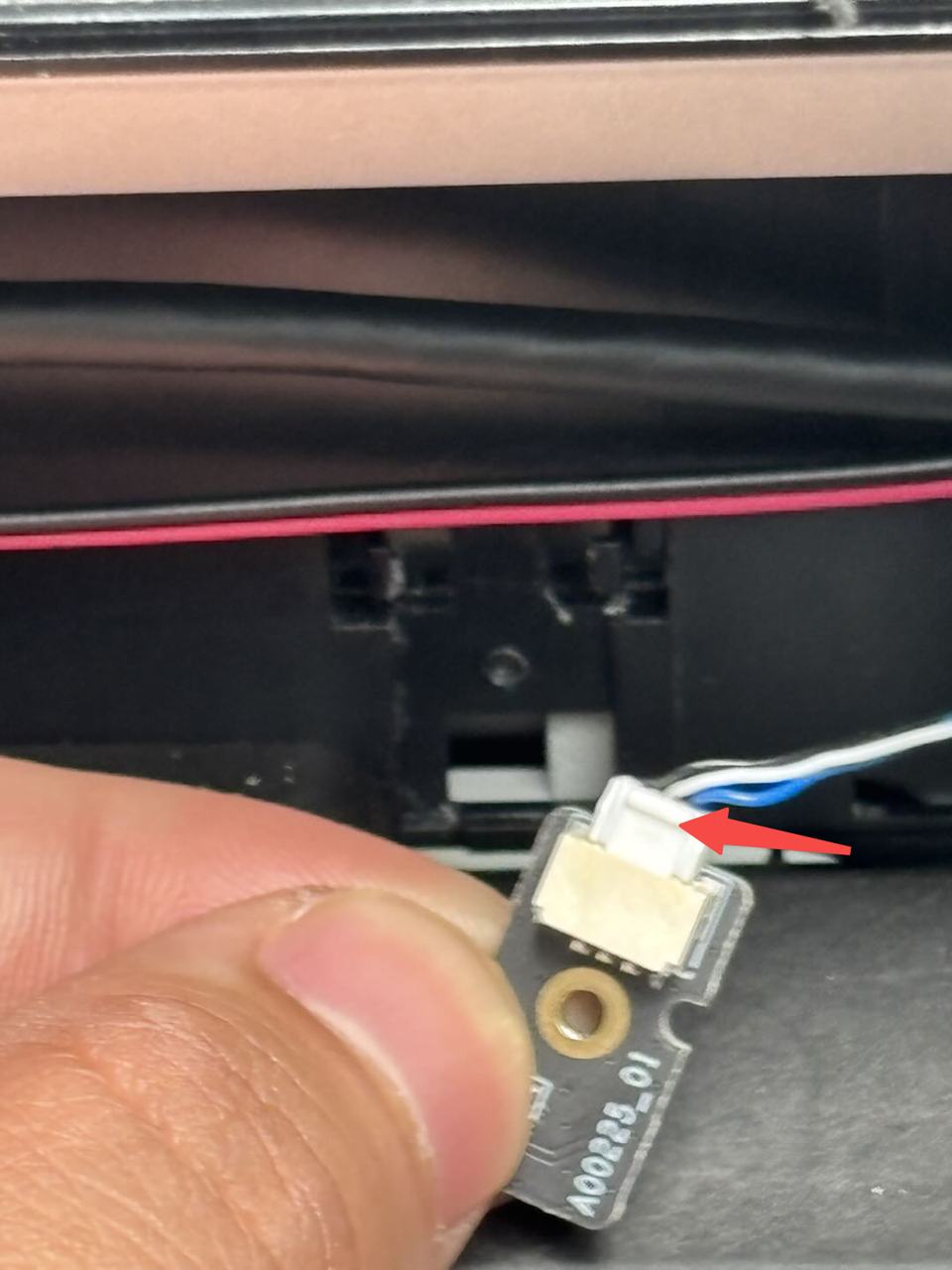
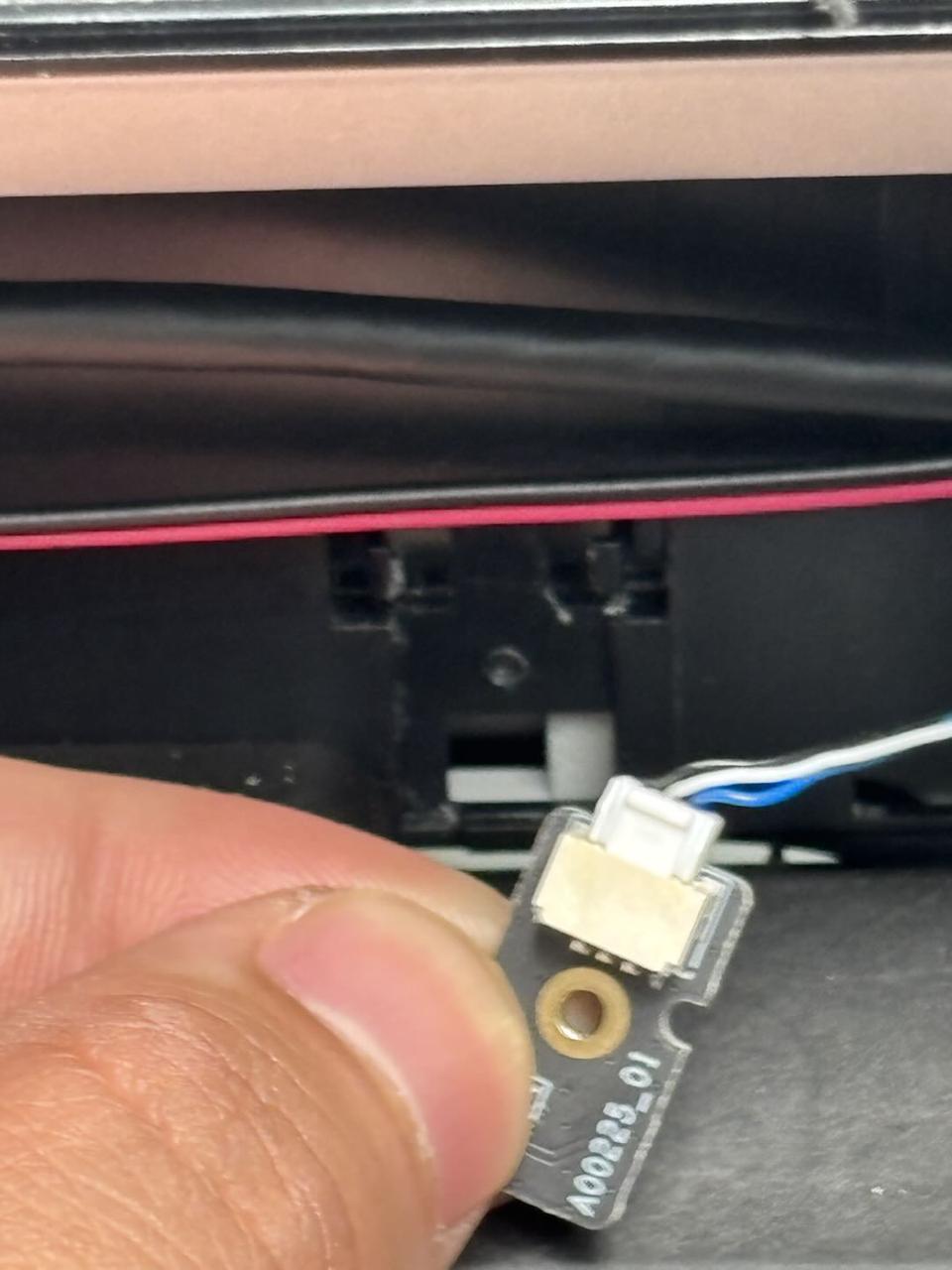
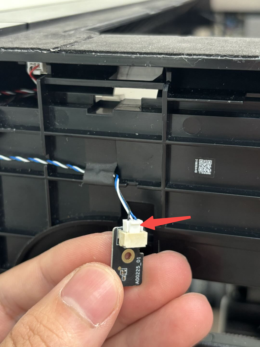
- Pull the hall effect sensor from the front of the printer (the side with the screen), press the clip to disconnect the hall effect sensor from the connector, and then remove the hall effect sensor.
¶ Install the Automatic Top Vent Detection Hall Effect Sensor
¶ Step 1: Install the hall effect sensor
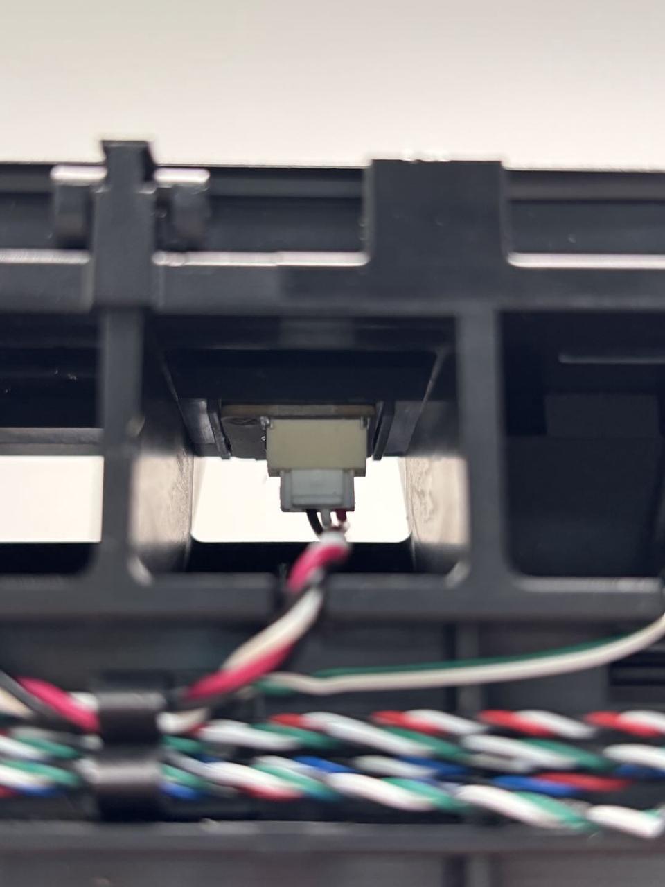
- Reconnect the new hall effect sensor to the connector and push the hall effect sensor back into the upper cover.
- Place the screw on the H1.5 Allen key, pass the screw through the screw hole in the middle of the hall effect sensor (use tweezers to assist if space is limited), and then tighten the screw (BT2x5).
Note: After tightening, check if the hall effect sensor is fully seated in the slot. If it is skewed, loosen the screw slightly and use the Allen key or tweezers to adjust the position of the hall effect sensor.
¶ Step 2: Install the front cover
You can refer to this Wiki to reinstall the front cover:
¶ Emergency Stop Button Detection Hall Effect Sensor
¶ Remove the Emergency Stop Button Detection Hall Effect Sensor
¶ Step 1: Tilt the printer to the right
The hall effect sensors are located at the bottom of the printer. It is recommended to tilt the printer to the right to access these two hall effect sensors.
Since the printer is heavy, it is advised to have two people slowly tilt the printer to avoid injury or damage during the operation.
¶ Step 2: Remove the hall effect sensor
Use a H1.5 Allen key to remove one fixing screw (M2x2.5), then disconnect the hall effect sensor from the connector to remove it.
The two hall effect sensors differ only in their placement but use the same screws. Both hall effect sensors can be removed using the same method.
There is glue around the two hall effect sensors, so you may need to apply slight force to remove them.

¶ Install the Emergency Stop Button Detection Hall Effect Sensor
¶ Step 1: Install the hall effect sensor
Connect the new hall effect sensor to the connector, then use a H1.5 Allen key to tighten one fixing screw (M2x2.5).
Replace the corresponding hall effect sensor as needed, paying attention to the placement during installation. Refer to the image below for specific placement.
¶ Step 2: Return the printer to upright position
After installation, return the printer to its upright position.
¶ Glass Cover Plate Detection Hall Effect Sensor
¶ Remove the Glass Cover Plate Detection Hall Effect Sensor
¶ Step 1: Peel off the foam
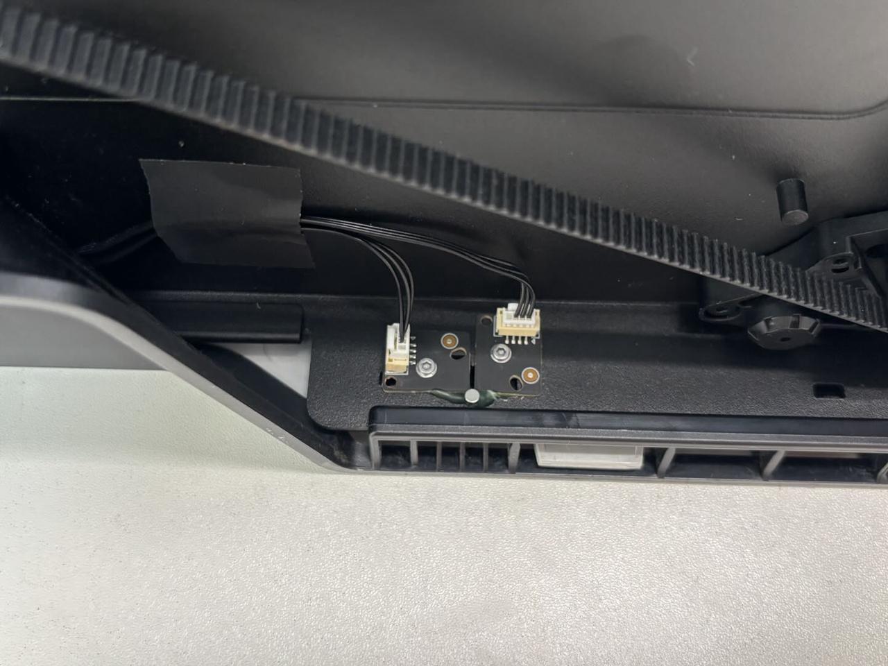
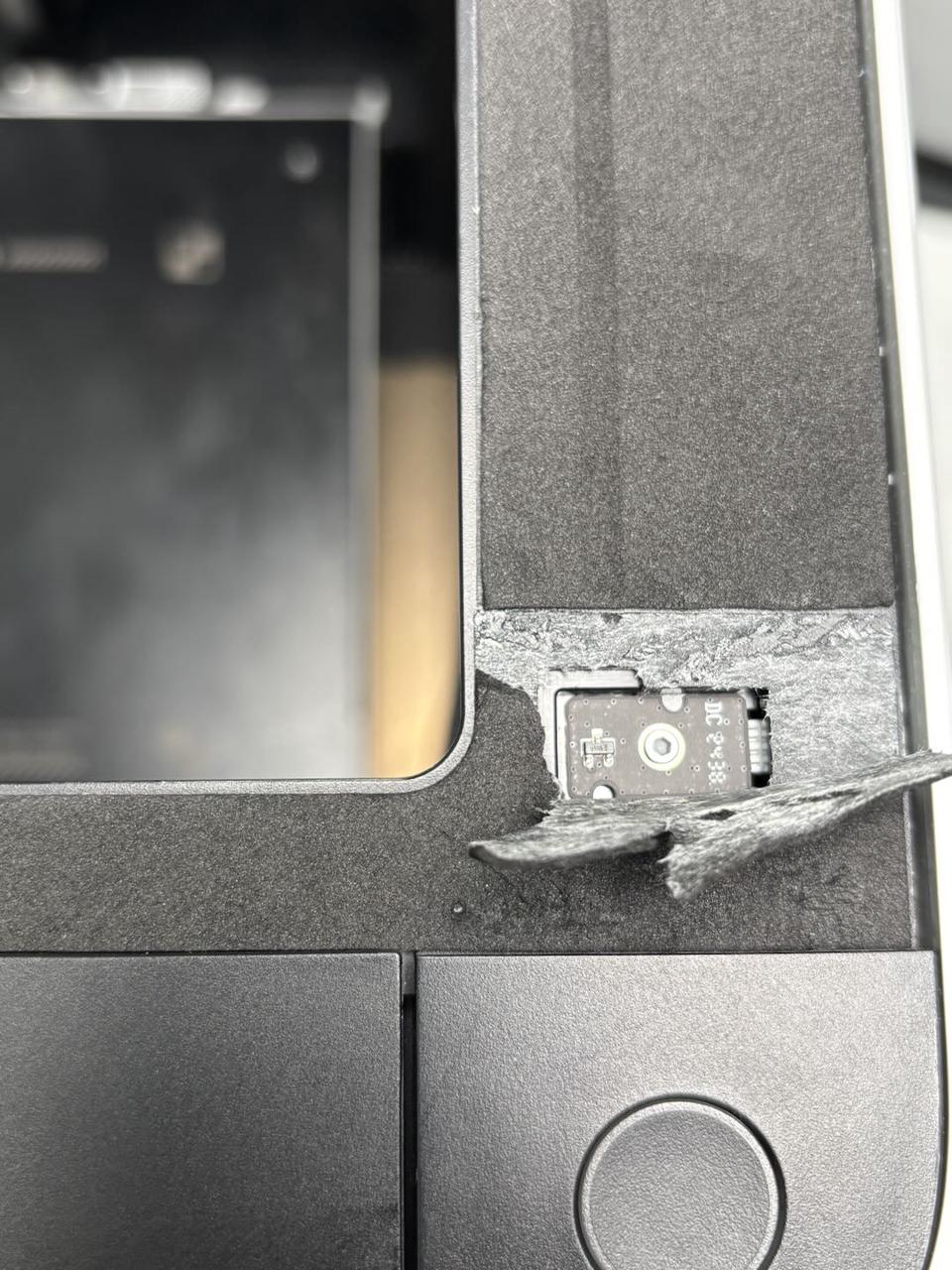
Both glass cover plate detection hall effect sensors are located underneath the foam. Carefully peel off the foam from the edge (avoid damaging the foam) until the hall effect sensors are fully exposed.

¶ Step 2: Remove the hall effect sensor
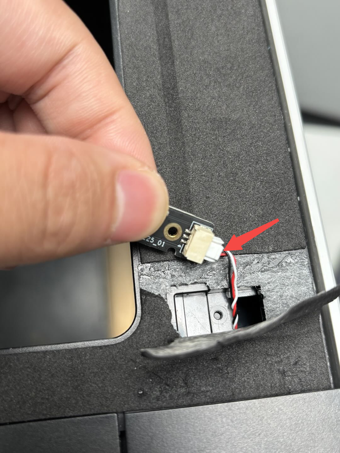
Use a H1.5 Allen key to remove one fixing screw (BT2x5). Then, gently pry the hall effect sensor slightly using the Allen key. Hold the front side of the hall effect sensor (the side opposite the connector) and remove it at an angle. Press the clip to disconnect the hall effect sensor from the connector.
Both hall effect sensors can be removed using the same method.
¶ Install the Glass Cover Plate Detection Hall Effect Sensor
¶ Step 1: Install the hall effect sensor
Connect the new hall effect sensor to the connector. Insert the side with the connector into position at an angle, then use a H1.5 Allen key to tighten one fixing screw (BT2x5).
Both hall effect sensors can be installed using the same method.

¶ Step 2: Reattach the foam
Reattach the original foam to cover the hall effect sensors.
¶ Left Side Panel Detection Hall Effect Sensor
¶ Remove the Left Side Panel Detection Hall Effect Sensor
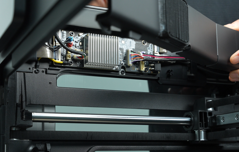
¶ Step 1: Remove the AP board cover
Use a H2.0 Allen key to remove one fixing screw (BT2.6x8). Then, take off the AP board cover from the side closer to the front door.
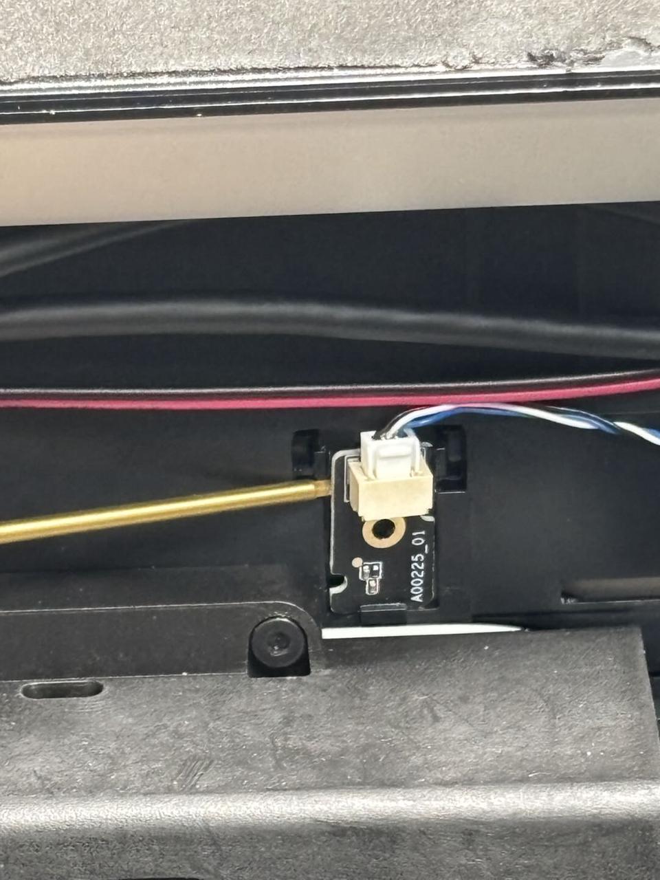
¶ Step 2: Remove the left side panel detection hall effect sensor
- Use a H1.5 Allen key to remove one fixing screw (M2x2.5).
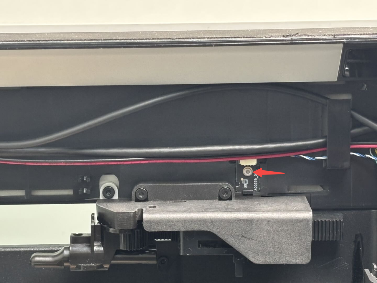
- In addition to the screw, the hall effect sensor is also secured by clips. You can use the Allen key to pry open the clips, then remove the hall effect sensor. Press the clip to disconnect the hall effect sensor from the connector.
¶ Install the Left Side Panel Detection Hall Effect Sensor
¶ Step 1: Install the hall effect sensor
- Connect the new hall effect sensor to the connector. First, insert the bottom of the hall effect sensor into place, then press it into the left and right clips (if the clips are bent, use the Allen key to pry them back into position).
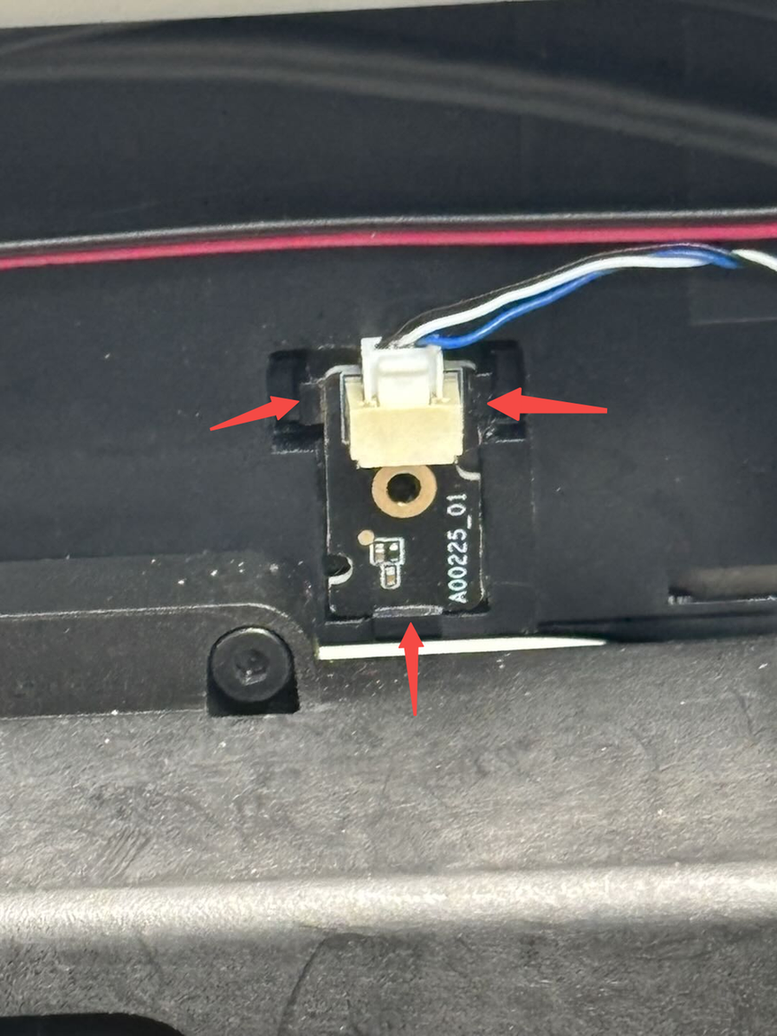
- Use a H1.5 Allen key to install one fixing screw (M2x2.5).

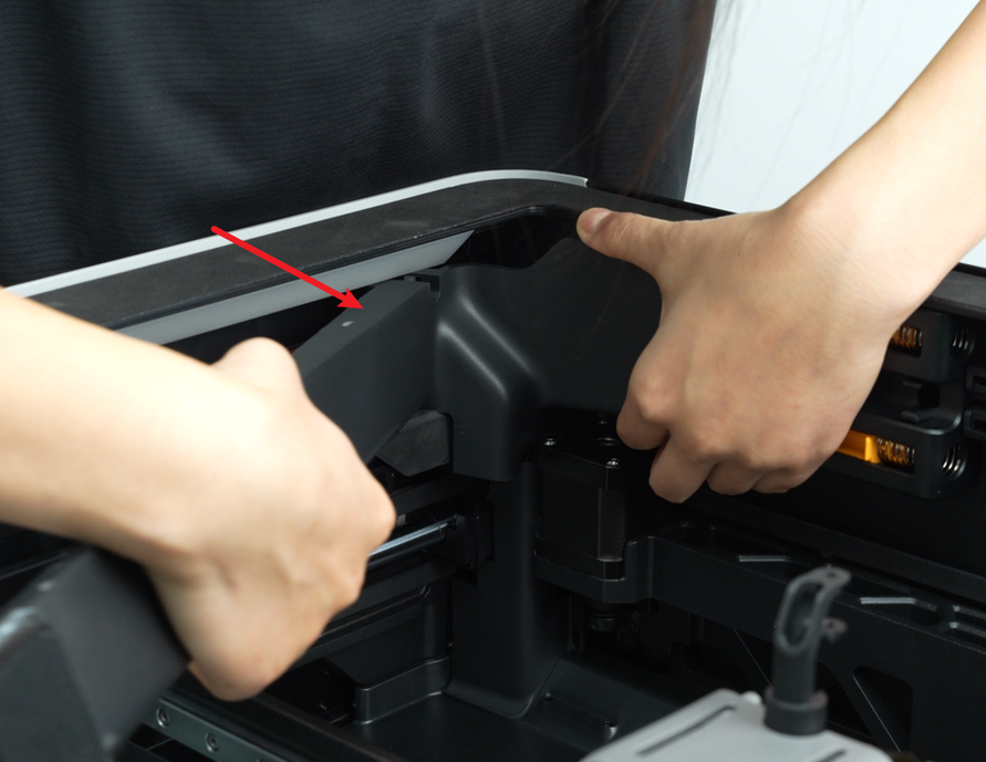
¶ Step 2: Install the AP board cover
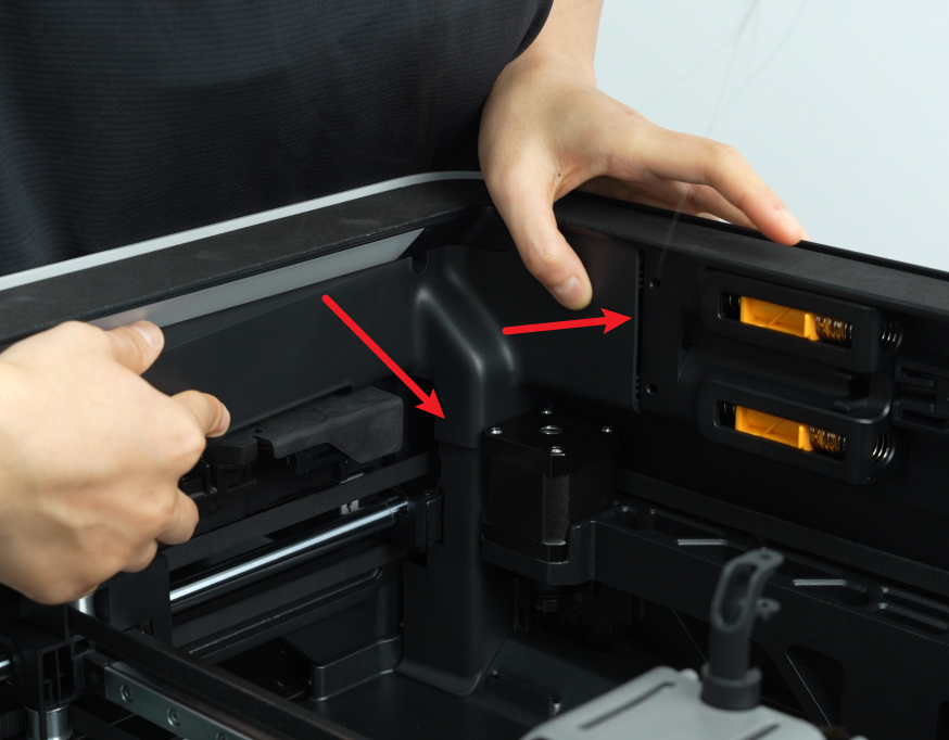
Start by reattaching the AP board cover from the side closer to the back of the printer. Press the two points indicated by the arrows into place, ensuring the right side aligns with the filament buffer and the bottom aligns with the cable cover. Then, use a H2.0 Allen key to tighten one fixing screw (BT2.6x8).

¶ Right Side Panel Detection Hall Effect Sensor
¶ Remove the Right Side Panel Detection Hall Effect Sensor
¶ Step 1: Remove the right side panel
Since the right side panel detection hall effect sensor is blocked behind the right side panel, you need to remove the right side panel first before you can remove the right side panel detection hall effect sensor. You can refer to this Wiki to remove the right side panel: Replace H2D Left/Right Side Panel
¶ Step 2: Remove the hall effect sensor
Use a H1.5 Allen key to remove one fixing screw (BT2x5), then press the clip to disconnect the connector from the hall effect sensor, and remove the hall effect sensor.
¶ Install the Right Side Panel Detection Hall Effect Sensor
¶ Step 1: Install the hall effect sensor
Reconnect the hall effect sensor to the connector, align it with the screw hole, and use a H1.5 Allen key to tighten one fixing screw (silver BT2x5).


¶ Step 2: Install the right side panel
You can refer to this Wiki to install the right side panel: Replace H2D Left/Right Side Panel
¶ Front Glass Door/Front Laser Safety Window Detection Hall Effect Sensor
¶ Remove the Front Glass Door/Front Laser Safety Window Detection Hall Effect Sensor
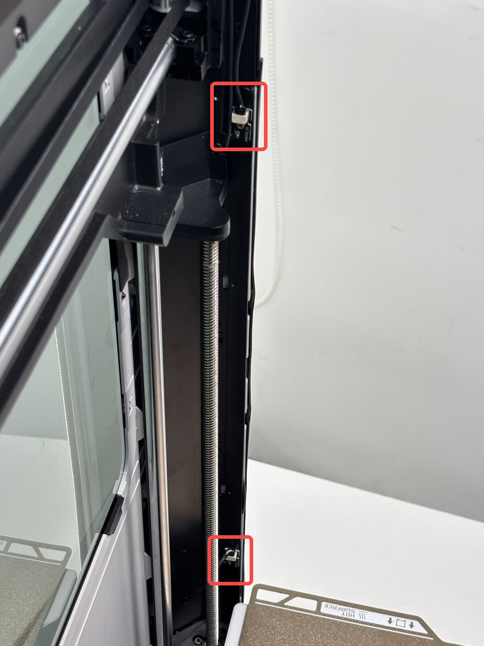
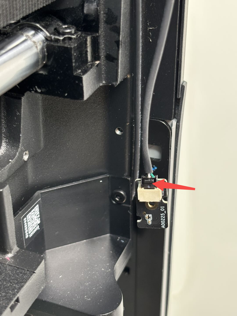
Both hall effect sensors are located on the inner side of the right front column. You can use a H1.5 Allen key to remove one fixing screw (M2x2.5), then disconnect the connector to remove the hall effect sensor.
One hall effect sensor is located at the top, and the other is at the bottom. You can operate the heatbed to rise or lower it on the screen to position it for easy access to the corresponding hall effect sensor, then power off the printer before proceeding with the operation.

¶ Install the Front Glass Door/Front Laser Safety Window Detection Hall Effect Sensor
Connect the new hall effect sensor to the connector, align it with the screw hole on the inner side of the column, and use a H1.5 Allen key to tighten one fixing screw (M2x2.5).
The same steps can be followed for both the upper and lower hall effect sensors.

¶ Verify the Functionality
Connect the power supply and turn on the printer, and no error message appears.
¶ End Notes
We hope the detailed guide provided has been helpful and informative.
If this guide does not solve your problem, please submit a technical ticket , we will answer your questions and provide assistance.
If you have any suggestions or feedback on this Wiki, please leave a message in the comment area. Thank you for your support and attention!