¶ Live View Camera
The live view camera is installed inside the printer, allowing you to monitor the printing process in real-time through Bambu Studio and Bambu Handy. It also supports features like spaghetti detection.
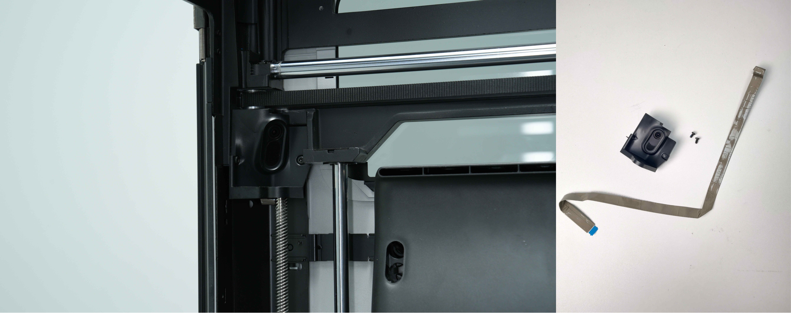
Spare Parts for Live View Camera:
- Live View Camera × 1 link to buy
- Live View Camera Connector (Replacement not needed if undamaged) × 1
- M3x6 Screws × 2
¶ When to Replace
- The live view camera connector is broken or damaged.
This wiki only provides instructions on how to replace the cable of camera. If the camera is damaged and needs to be replaced, please refer to this wiki link.
¶ Tools and Materials Needed
- New live view camera
- H2.0 Allen key
¶ Safety Warning
IMPORTANT!
It's crucial to power off the printer before conducting any maintenance work, including work on the printer's electronics and tool head wires. Performing tasks with the printer on can result in a short circuit, leading to electronic damage and safety hazards.
During maintenance or troubleshooting, you may need to disassemble parts, including the hotend. This exposes wires and electrical components that could short circuit if they contact each other, other metal, or electronic components while the printer is still on. This can result in damage to the printer's electronics and additional issues.
Therefore, it's crucial to turn off the printer and disconnect it from the power source before conducting any maintenance. This prevents short circuits or damage to the printer's electronics, ensuring safe and effective maintenance. For any concerns or questions about following this guide, we recommend submitting a technical ticket regarding your issue and we will do our best to respond promptly and provide the assistance you need.
¶ Replace the Live View Camera Connector
¶ Remove the Live Camera Connector
¶ Step 1: Remove the AP board cover
Use an H2.0 Allen key to remove 1 fixing screw (BT2.6x8), and then remove the AP board cover from the side near the front door.
.png)
¶ Step 2: Remove the left side panel
The left side panel can be removed by following the Wiki guide: replace-side-panel-with-glass-window
¶ Step 3: Remove the live view camera
-
Use an H2.0 Allen key to remove the two fixing screws (M3x6), and then remove the live view camera from the side close to the front door.
.png)
-
Lift the black clasp above the live view camera connector and pull out the connector.
.png)
¶ Step 4: Remove the live view camera connector
-
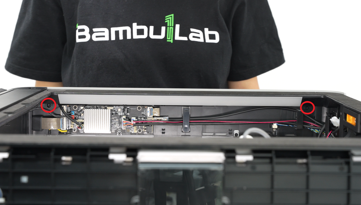
Unfasten the buckle that connects the live view camera cable to the AP board, and then remove the live view camera connector from the interface on the AP board;
.png)
-
Then pull the camera connector out of the small hole in the upper frame and tear off the connector attached to the printer to remove it.
¶ Install the Live Camera Connector
¶ Step 1: Connect the AP board
When installing the live view camera connector, you need to pay attention to the direction. "AP" is printed on one end of the connector, indicating that this end is connected to the AP board:
.png)
-
Pass the end of the live view camera connector with "AP" printed on it through the upper frame.
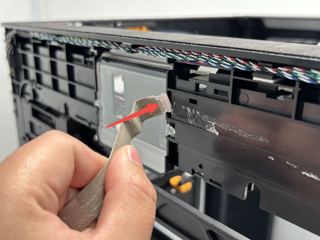
-
Then insert it into the interface of the AP board and fasten the buckle;
.png)
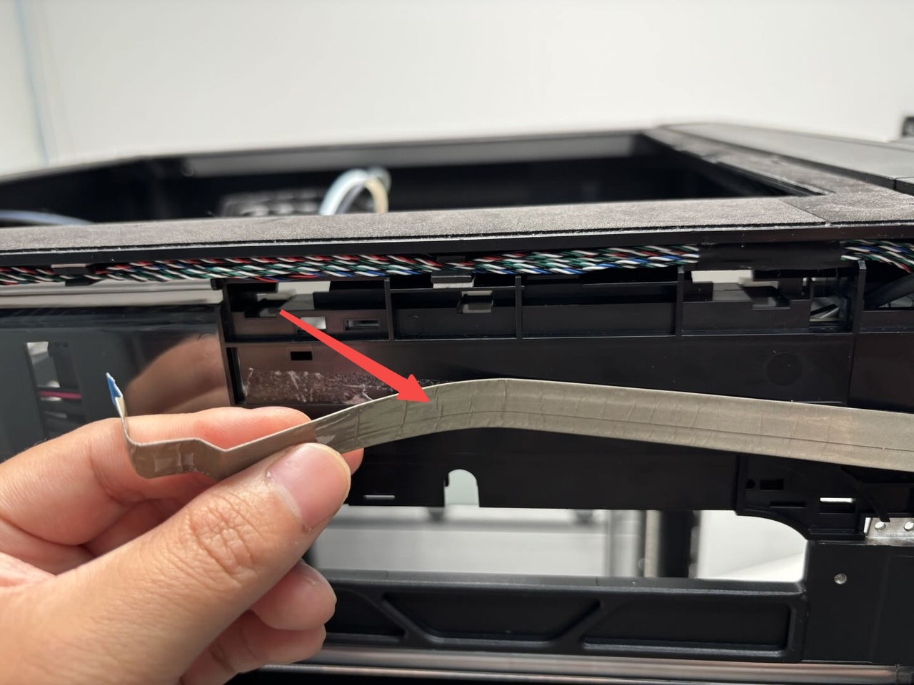
-
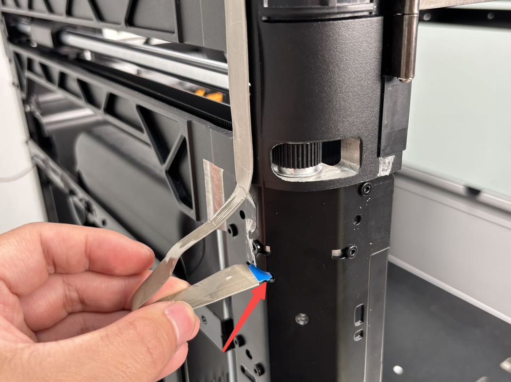
Tear off the adhesive backing of the live view camera connector, stick the cable on the printer according to the figure below (you can fold the cable at the place indicated by the arrow to facilitate sticking).
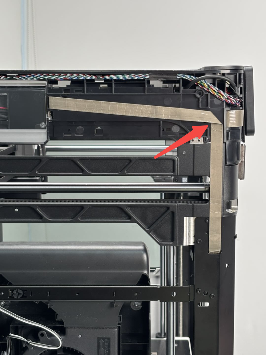
-
And then insert the other end into the small hole of the printer pillar.
¶ Step 2: Fix the live view camera
- Insert the live view camera connector into the live view camera, and fasten the black buckle.
.png)
Note that the cable should be placed in place.
-
Hold the left side of the live view camera, install the right side of the camera first, then the left side, and align the screw holes.
.png)
-
Finally, use an H2.0 Allen key to tighten the two fixing screws (M3x6).

¶ Step 3: Install the left side panel
The left side panel can be installed by following the Wiki guide in the following link:replace-side-panel-with-glass-window
¶ Step 4: Install the AP board cover
First, snap the AP board cover back from the side close to the back of the printer, and then tighten a fixing screw (BT2.6x8) using an H2.0 Allen key.
.png)
¶ Verify the Functionality
Connect the power cable and turn on the printer. In Bambu Studio or Bambu Handy, click the Play button to check if the video streams normally.
If the video does not display correctly, verify that the connectors are properly connected and try again. If the issue persists, contact Bambu Lab Technical Support for further assistance.
¶ Screw type
Specifications and quantities of screws involved in replacing the H2D live view camera/live view camera connector (it is recommended to keep the removed screws properly to avoid loss):
| Specification | Use | Position | Quantity | ||
|---|---|---|---|---|---|
| M3x6 | Fix the live view camera | 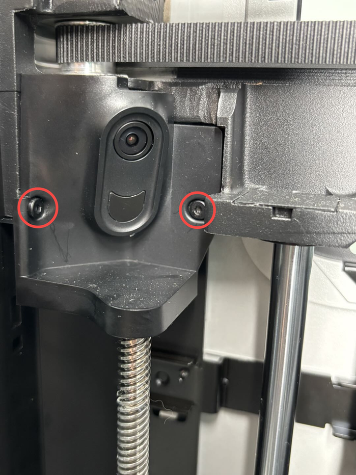 |
2 | ||
| BT2.6x8 | Fix the AP board cover | 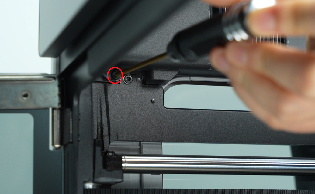 |
1 | ||
| ST3x6 | Fix the rear panel (marked with red circle) |  |
11 | ||
| ST3x12 | Fixed spool holder bracket (marked with yellow square) | 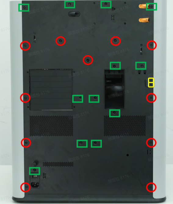 |
2 | ||
| M3x3(nut diameter 10mm) | Fix the front glass door | 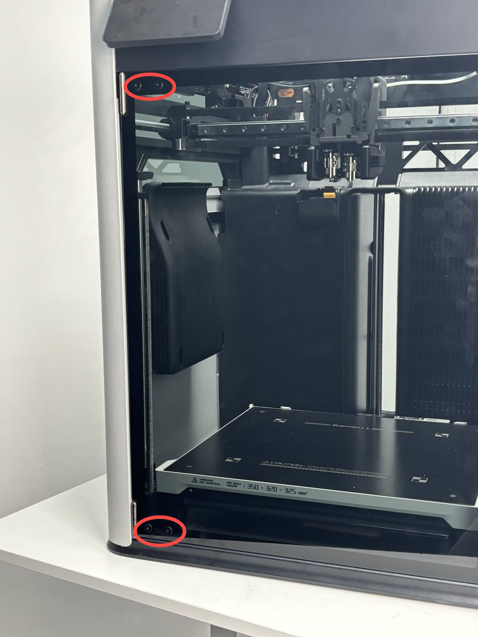 |
4 | ||
| BT3x16 | Fix the auxiliary part cooling fan |  |
2 | ||
| BT3x8 | Fix the left side panel | 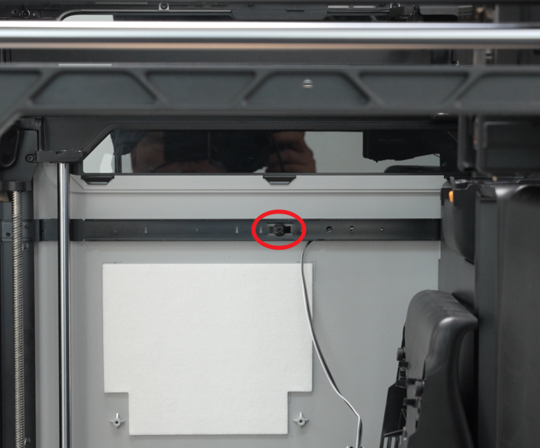 |
 |
3 | |
| Fix the rear panel (marked with green square) |  |
12 | |||
| ST3x3 | Fix the left side panel | 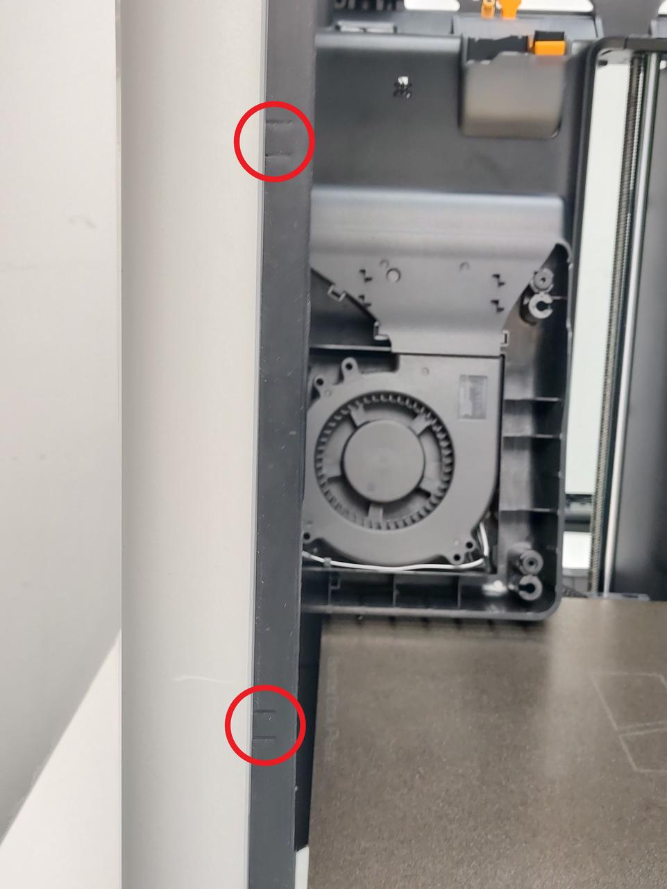 |
2 |
¶ End Notes
We hope the detailed guide provided has been helpful and informative.
If this guide does not solve your problem, please submit a technical ticket, we will answer your questions and provide assistance.
If you have any suggestions or feedback on this Wiki, please leave a message in the comment area. Thank you for your support and attention!