¶ Nozzle Lifting Rail
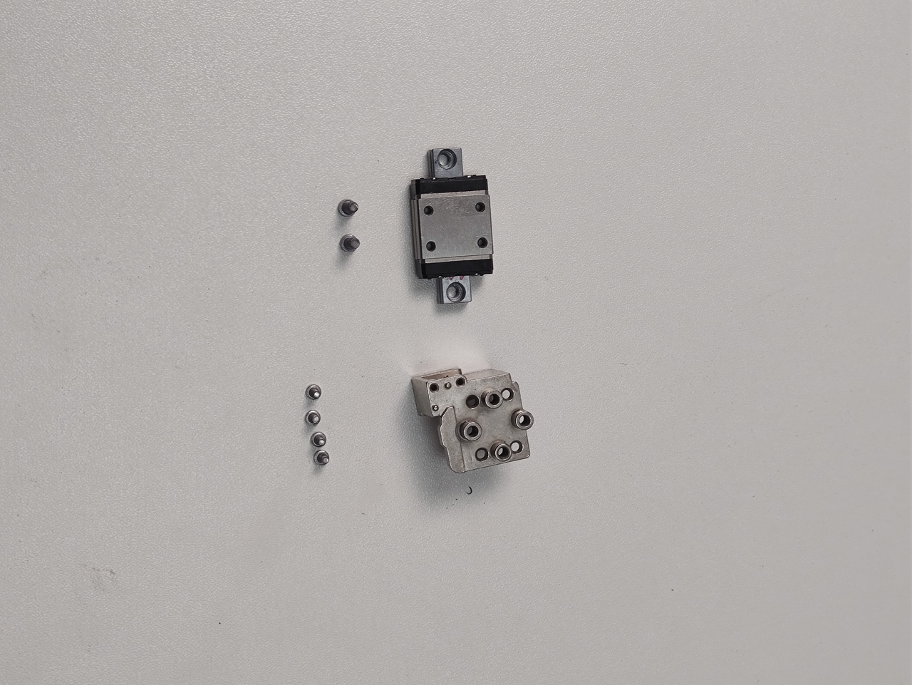
The nozzle lifting rail is installed on the back of the left hotend heating assembly and consists of a lifting rail and a lifting slider. The components and details of the nozzle lifting rail are as follows:
-
Lifting slider * 1
-
Lifting rail * 1
-
M2x4.5 screws - used to fix the lifting slider and lifting rail * 4
-
M2.5x7 screws - used to fix the lifting rail and lifting bracket * 2
¶ When to use
-
The lifting rail makes abnormal noise;
-
The movement of the lifting rail is stiff;
-
The lifting slider is damaged.
¶ Tools and Materials Needed
-
New lifting rail
-
H2.0 Allen key
¶ Safety Warning
IMPORTANT!
It's crucial to power off the printer before conducting any maintenance work, including work on the printer's electronics and tool head wires. Performing tasks with the printer on can result in a short circuit, leading to electronic damage and safety hazards.
During maintenance or troubleshooting, you may need to disassemble parts, including the hotend. This exposes wires and electrical components that could short circuit if they contact each other, other metal, or electronic components while the printer is still on. This can result in damage to the printer's electronics and additional issues.
Therefore, it's crucial to turn off the printer and disconnect it from the power source before conducting any maintenance. This prevents short circuits or damage to the printer's electronics, ensuring safe and effective maintenance. For any concerns or questions about following this guide, we recommend submitting a technical ticket regarding your issue and we will do our best to respond promptly and provide the assistance you need.
¶ Remove the Nozzle Lifting Rail
¶ Step 1. Remove the part cooling fan and air duct
Refer to this Wiki for instructions on how to remove the part cooling fan and air duct:
Replace the H2D Part Cooling Fan Air Duct
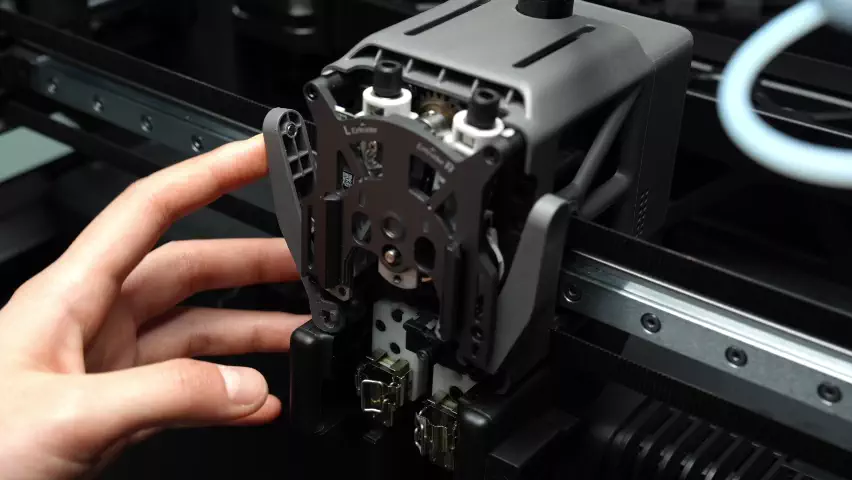
¶ Step 2. Remove the left hotend and left hotend heating assembly
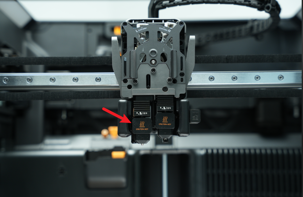
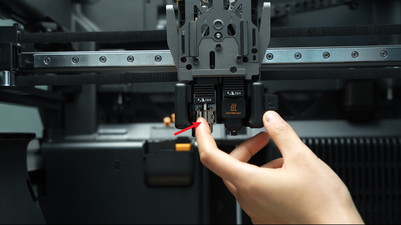
- Remove the left silicone sock for hotend, unlock the hotend buckle, and detach the hotend from the toolhead.
To switch to the left hotend, either click the switch on the screen or manually toggle the lifting arm after turning off and disconnecting the power.
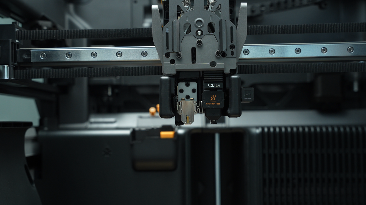
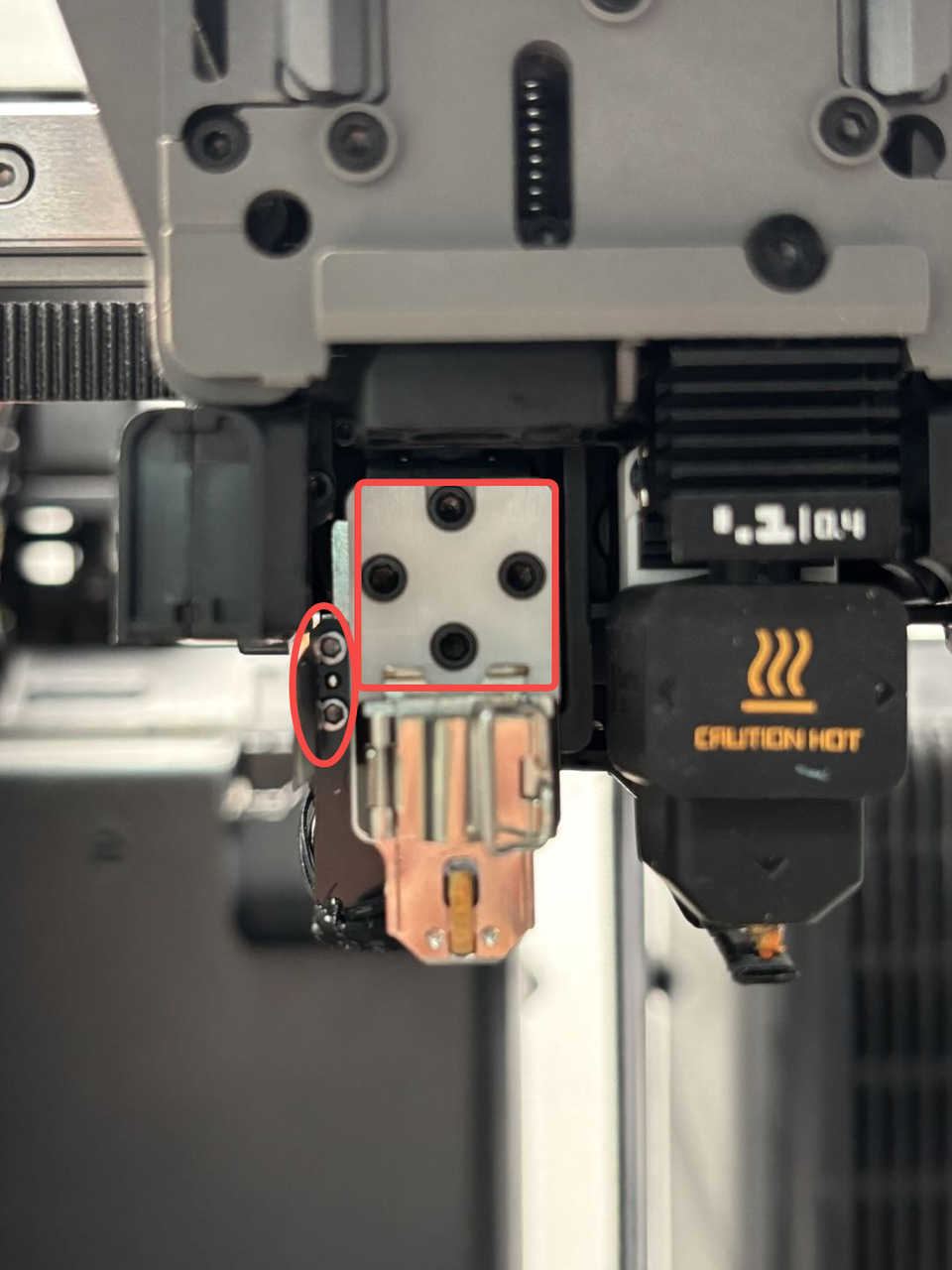
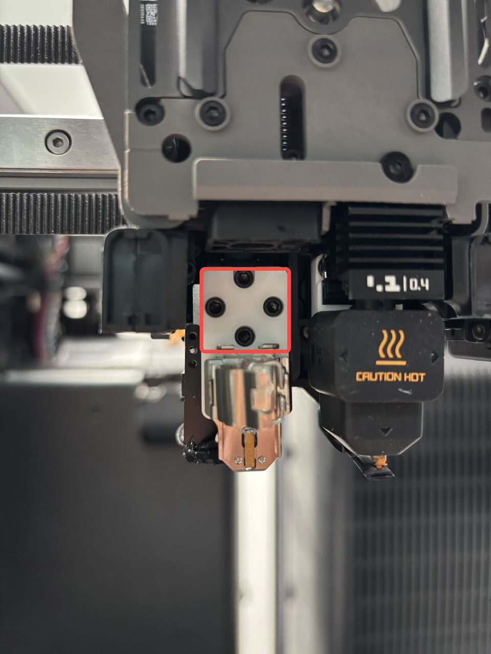
- Use the H2.0 Allen key to remove the 4 hotend fixing screws (M2.5x7, marked by squares), then use the H1.5 Allen key to remove the 2 cable sheet/wind blocker fixing screws (M1.6x4, marked by ellipses). Detach the hotend from the lifting slider without disconnecting it from the TH board.
¶ Step 3. Remove the left hotend cooling fan air duct
Use the H1.5 Allen key to remove one fixing screw and slide the left hotend cooling fan air duct forward to remove it.
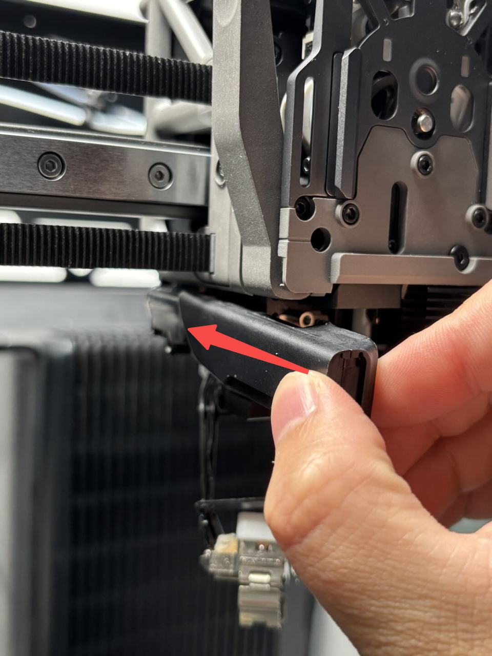
¶ Step 4. Remove the dual extruder filament guide
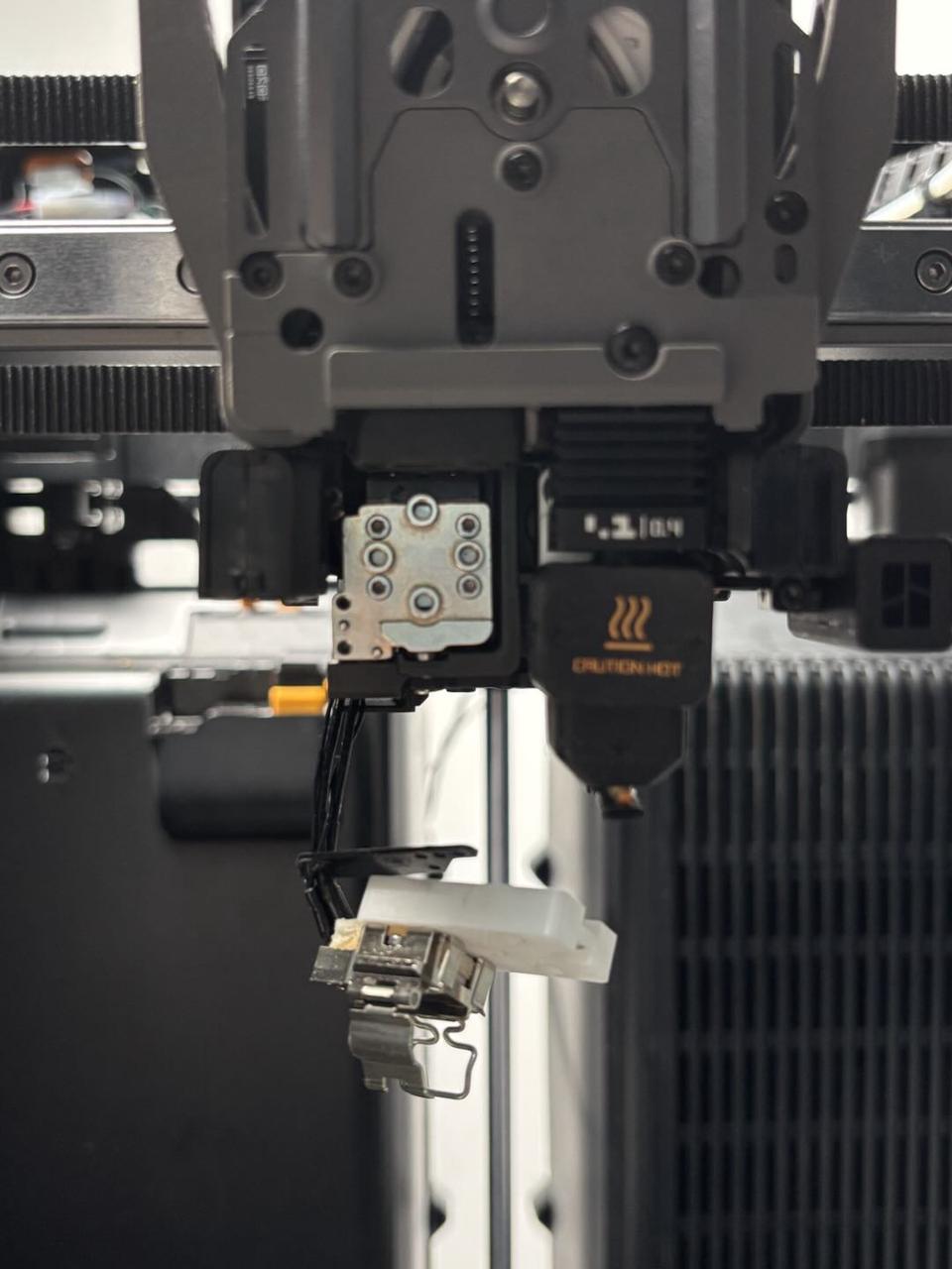
After unscrewing the three or four screws (M2.5x7 * 3;BT2x6 * 1) on the extruder filament guide, use your fingers to press upward against the black hotend connector while simultaneously pressing down on the left cutter lever to release it slightly from the opening slot near the cutter screw.
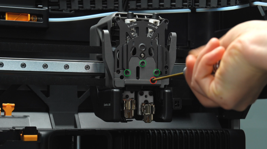
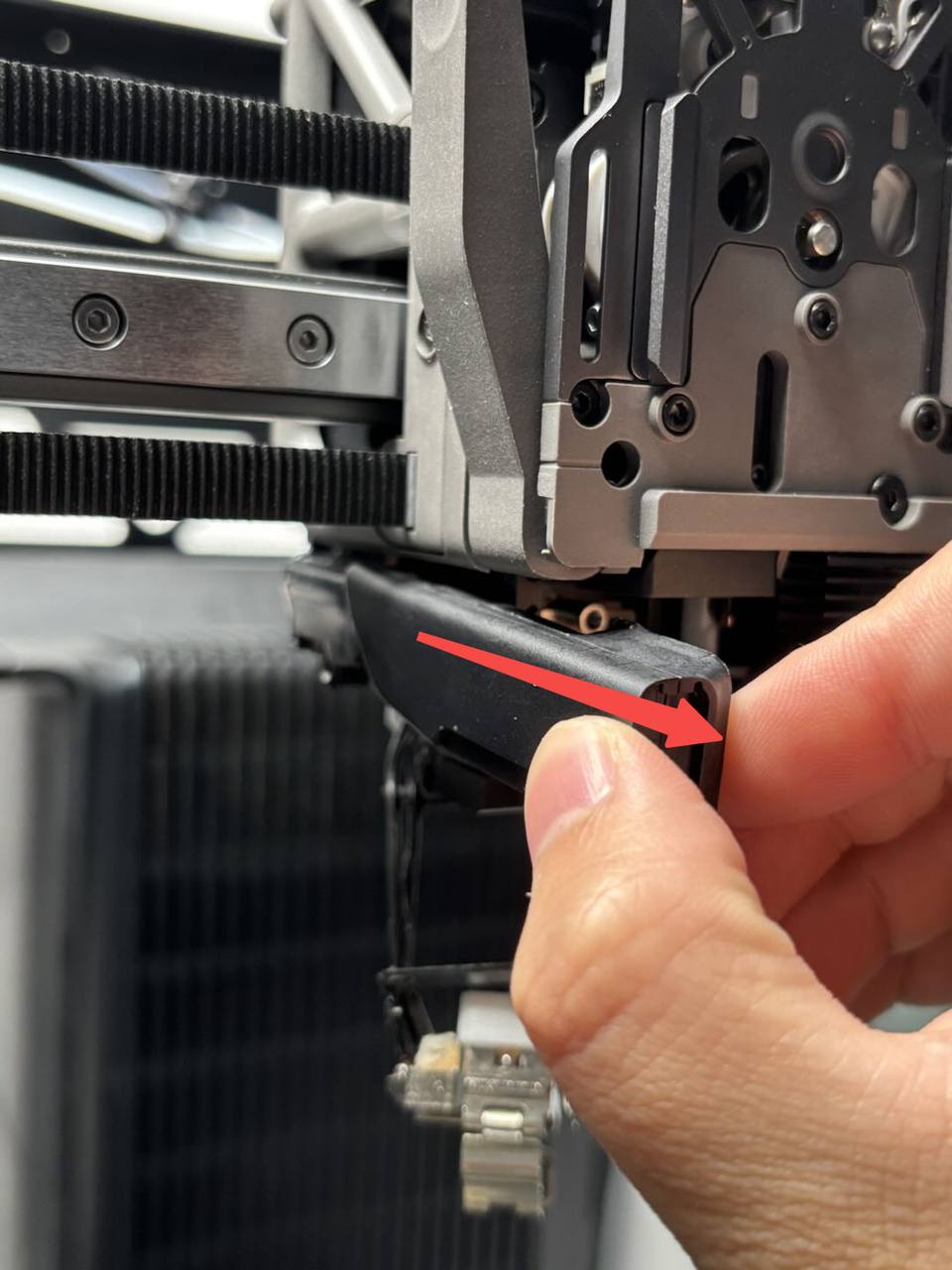
Then, exert force outward from the lower right corner of the extruder filament guide to pry it out.
The left cutter is located within the extruder filament guide and will be removed together when removing the extruder filament guide. Please take care to store it properly to prevent loss.
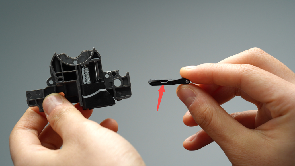
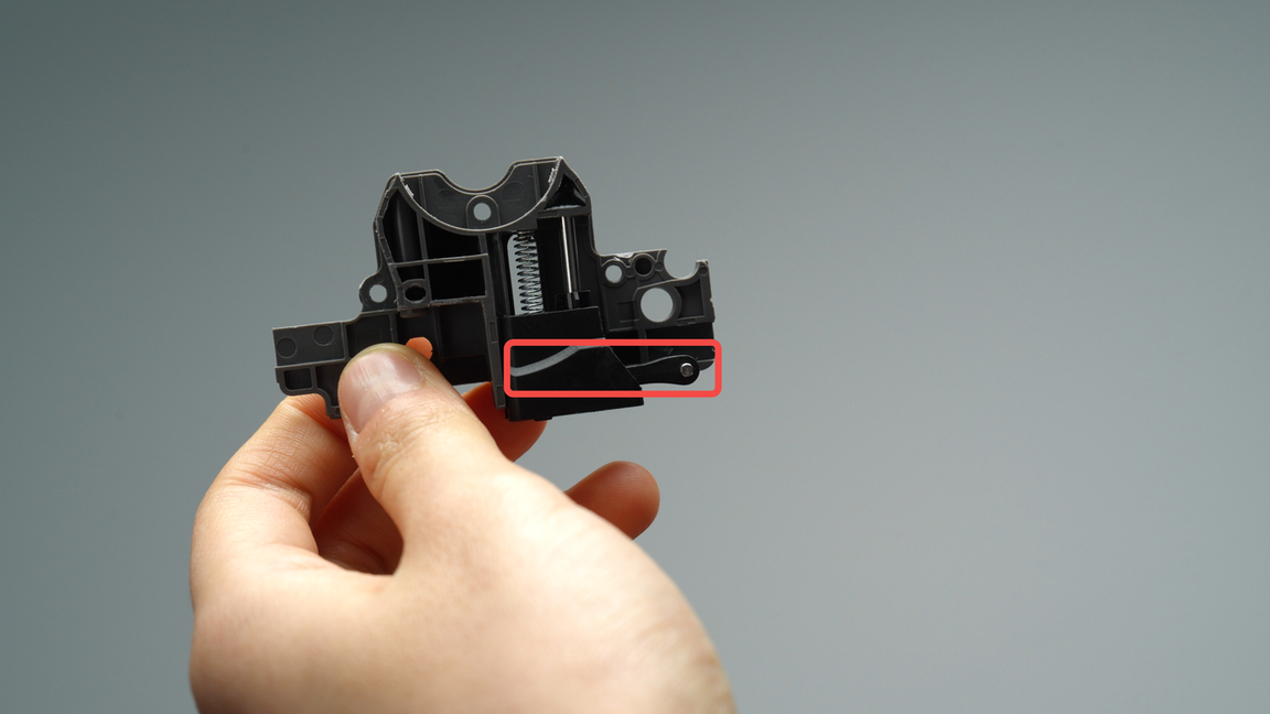
Note: It is not necessary to remove the black slider on top when disassembling the front guide.
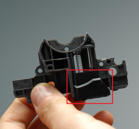
If you accidentally remove the slider, please make sure to install the spring correctly. Examples are shown below:
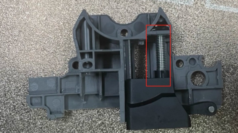
Incorrect
|
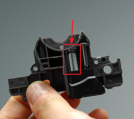
Correct
|
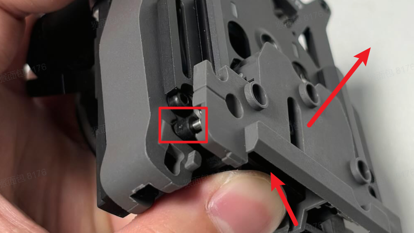
If the spring is installed incorrectly, you can fix it by following the steps below:
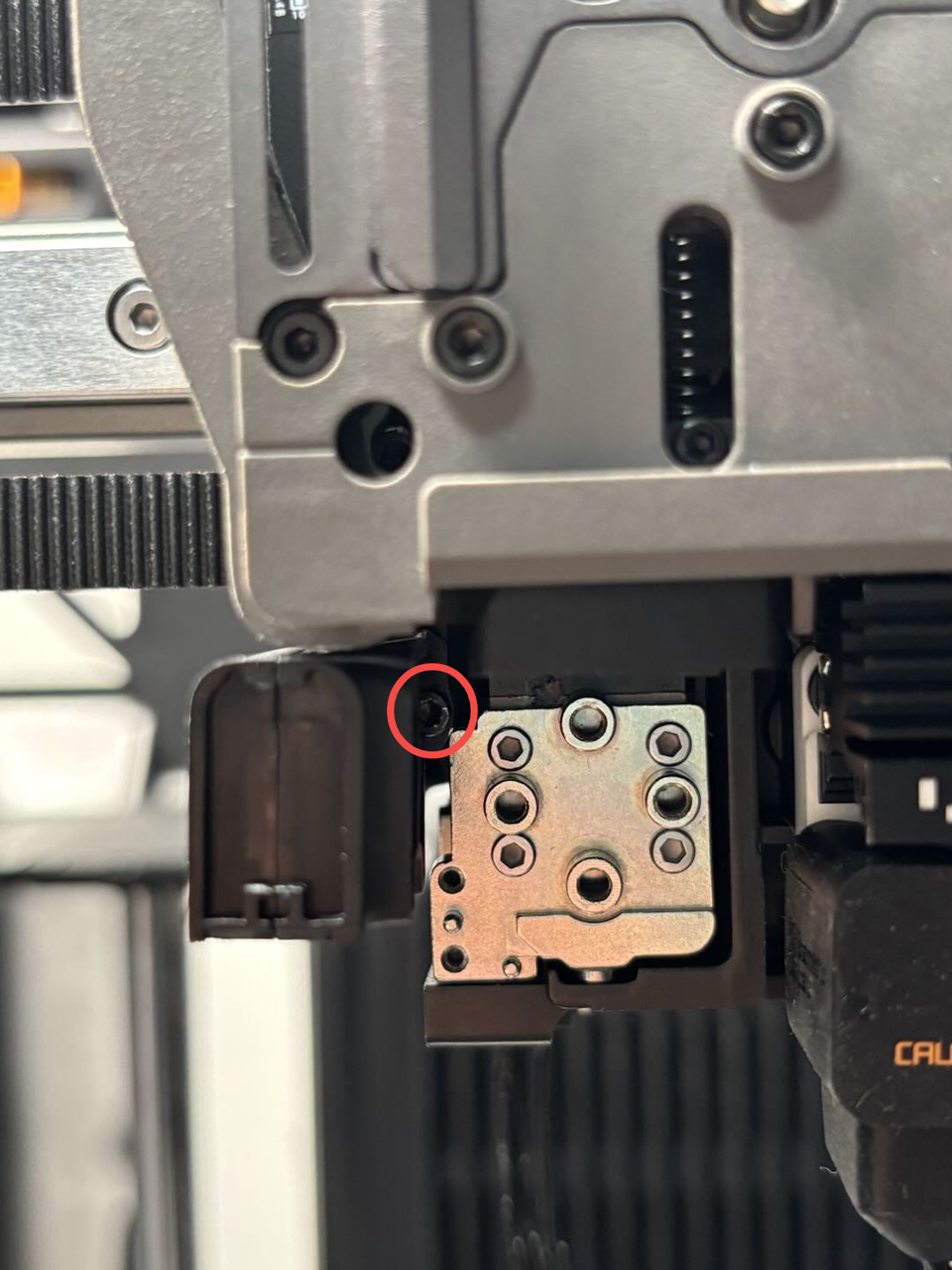
When the spring is misplaced, look from the right to the left at the position shown above, where you will find a small screw (size 1.5).
From the right side, locate the 1.5 screw. Loosen it with a 1.5 mm hex key, remove the black slider, and reinstall the spring correctly.
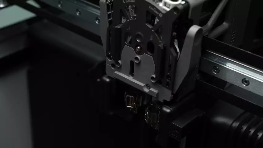
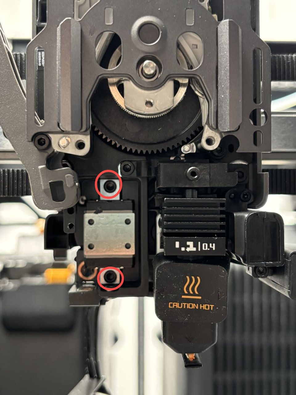
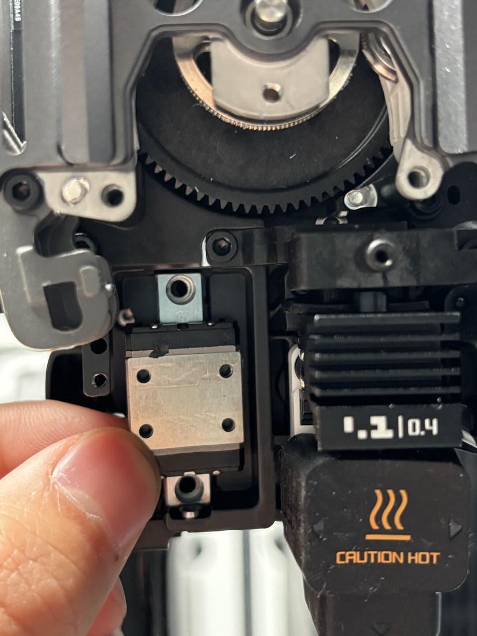
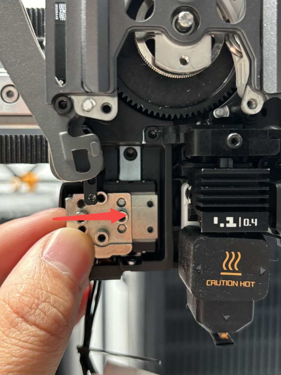
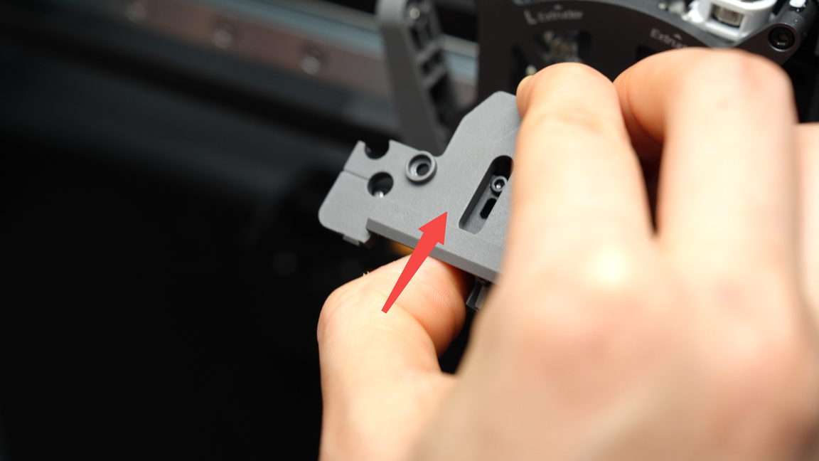
¶ Step 6. Remove the lifting slider and lifting rail
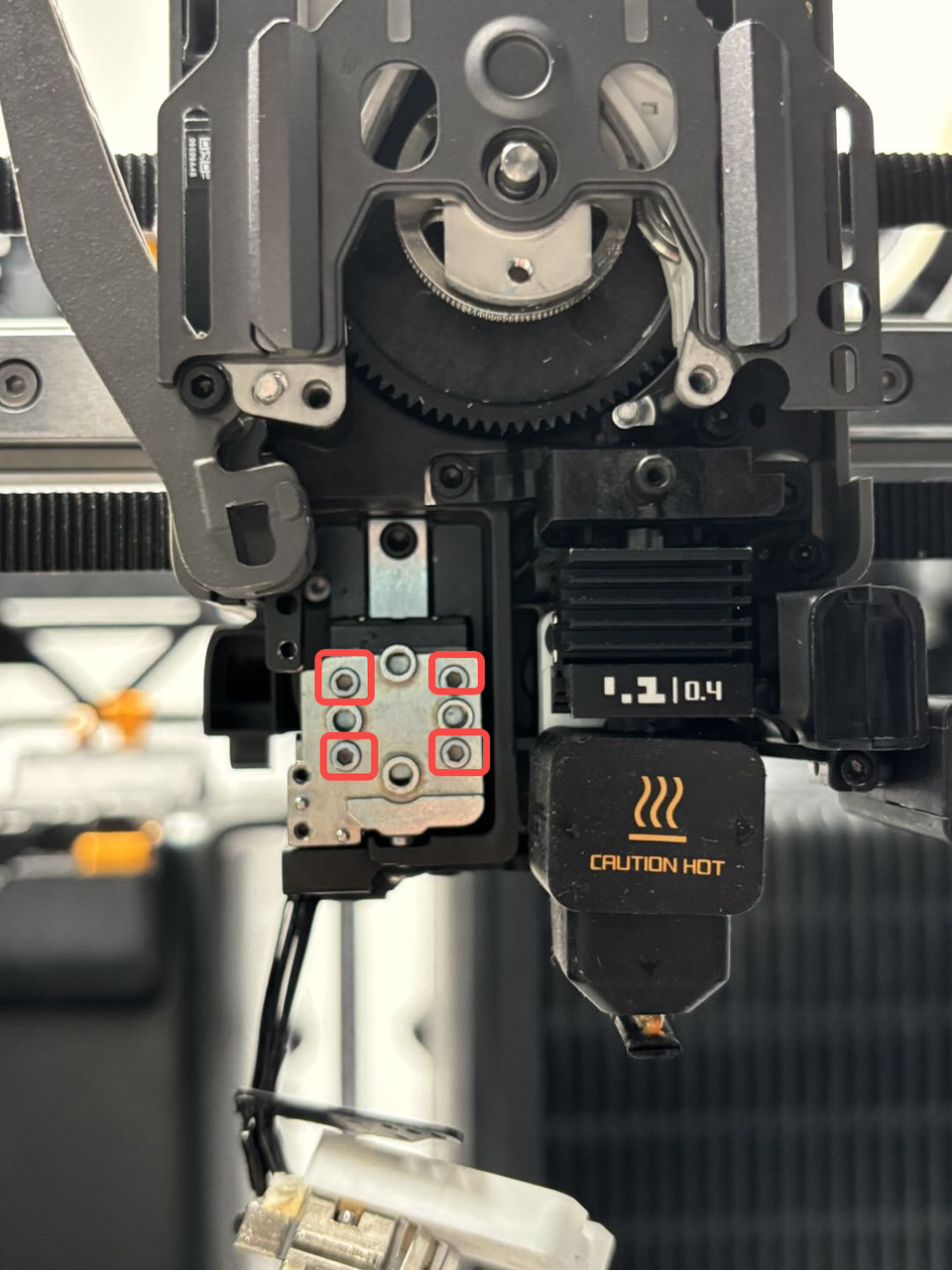
- Use the H2.0 Allen key to remove the 4 lifting slider fixing screws and carefully slide out the lifting slider from the left side.
Be cautious to avoid touching the left eddy current coil!

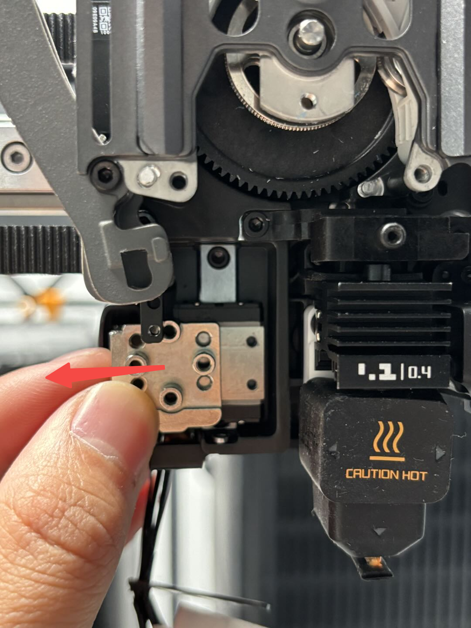
- Use the H2.0 Allen key to remove the 2 lifting rail fixing screws and slide the lifting rail forward to remove it.

¶ Install the Nozzle Lifting Rail
¶ Step 1. Install the lifting slider and lifting rail
- Insert the new lifting rail into the lifting bracket from the front and use the H2.0 Allen key to tighten the 2 fixing screws.

- Insert the new lifting slider into the lifting rail from the left side and use the H2.0 Allen key to tighten the 4 fixing screws.
Be cautious to avoid touching the left eddy current coil!
- Verification: Use A4 paper to check the gap between the left eddy current coil and the lifting slider. The paper should be able to slide through. Typically, the gap between the left eddy current coil and the lifting slider is around 0.2mm, which is approximately the thickness of a folded A4 paper (0.2mm).
¶ Step 2. Install the dual extruder filament guide
The left cutter needs to be installed together with the extruder filament guide. Ensure that the notch of the left cutter is facing upwards, then place it into the cutting blade slot of the extruder filament guide.
When installing the extruder filament guide, make sure to continuously press upwards against the black hotend connector and simultaneously press the left cutter lever, adjusting it to an appropriate angle for easy insertion.
Then, install the extruder filament guide. Finally, press on both sides of the cutter lever, applying force to completely flatten the front cover.
Then, tighten the four screws (M2.5x7 * 3;BT2x6 * 1) on the extruder filament guide.
¶ Step 3. Install the left hotend cooling fan air duct
- Insert the left hotend cooling fan air duct into the hotend cooling fan air duct and use the H1.5 Allen key to tighten one fixing screw.

¶ Step 4. Install the left hotend and left hotend heating assembly
First, align the new left hotend heating assembly and the cable sheet with the screw holes on the toolhead, and use an H2.0 Allen key to tighten the 4 left hotend heating assembly fixing screws (M2.5x7, marked with squares); then place the cable sheet, and use an H1.5 Allen key to tighten the 2 fixing screws (M1.6x4, marked with eliipses).

¶ Step 5. Install the part cooling fan air duct
Refer to this Wiki for instructions on how to install the part cooling fan air duct:
Replace the H2D Part Cooling Fan Air Duct
¶ Verify the Functionality
Connect the power and turn on the printer. Switch to the right hotend and then back to the left hotend to confirm the switching functionality. Click the homing button and check if it homes properly.
¶ End Notes
We hope the detailed guide provided has been helpful and informative.
If this guide does not solve your problem, please submit a technical ticket, we will answer your questions and provide assistance.
If you have any suggestions or feedback on this Wiki, please leave a message in the comment area. Thank you for your support and attention!