¶ Nozzle Offset Calibration Sensor
The nozzle offset calibration sensor is installed at the rear of the heatbed.
The spare parts for the nozzle offset calibration sensor include:
-
Nozzle offset calibration sensor * 1
-
Nozzle offset calibration sensor connector * 1
-
M2x5 screws (used to fix the nozzle offset calibration sensor) * 2
¶ Tools and Materials Needed
-
New nozzle offset calibration sensor
-
H1.5 Allen key
-
H2.0 Allen key (required only when replacing the nozzle offset calibration sensor connector)
¶ Safety Warning
IMPORTANT!
It's crucial to power off the printer before conducting any maintenance work, including work on the printer's electronics and tool head wires. Performing tasks with the printer on can result in a short circuit, leading to electronic damage and safety hazards.
During maintenance or troubleshooting, you may need to disassemble parts, including the hotend. This exposes wires and electrical components that could short circuit if they contact each other, other metal, or electronic components while the printer is still on. This can result in damage to the printer's electronics and additional issues.
Therefore, it's crucial to turn off the printer and disconnect it from the power source before conducting any maintenance. This prevents short circuits or damage to the printer's electronics, ensuring safe and effective maintenance. For any concerns or questions about following this guide, we recommend submitting a technical ticket regarding your issue and we will do our best to respond promptly and provide the assistance you need.
¶ Replace the Nozzle Offset Calibration Sensor
¶ Remove the nozzle offset calibration sensor
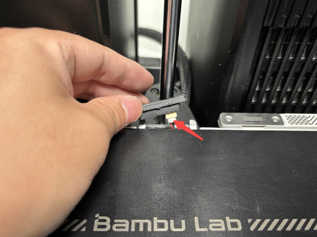
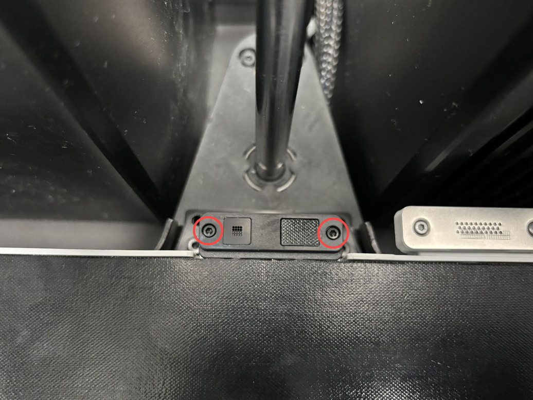
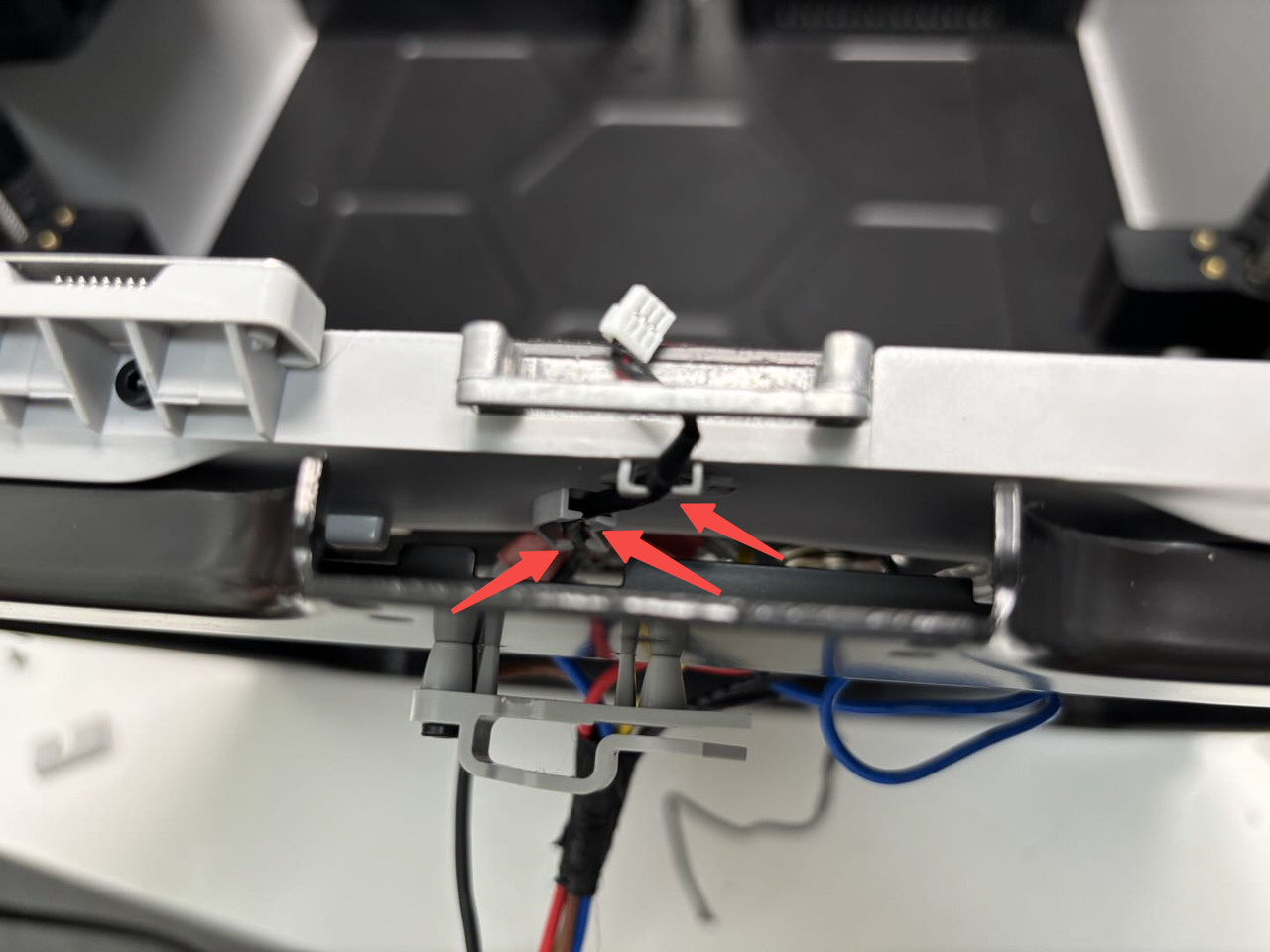
Use an H1.5 Allen key to remove the 2 fixing screws (M2x5) securing the nozzle offset calibration sensor coil. Gently lift the calibration coil upwards and disconnect the connector.
 |
 |
¶ Install the nozzle offset calibration sensor
Attach the nozzle offset calibration coil to the heatbed connector and secure the calibration coil with 2 screws (M2x5) using an H1.5 Allen key.
 |
 |
¶ Replace the Nozzle Offset Calibration Sensor Connector
¶ Remove the nozzle offset calibration sensor connector
¶ Step 1: Remove the heatbed
Please refer to the steps available in the H2D Headbed Replacement Guide to remove the heatbed and nozzle offset calibration sensor.
¶ Step 2: Remove the nozzle offset calibration sensor connector
- Flip the heatbed over, use an H2.0 Allen key to remove the cable cover fixing screw (BT3x8). There is a small silicone piece on the heatbed cable cover; remove it before taking off the cable cover. Then, use an H2.0 Allen key to remove one heatbed cable clip fixing screw (ST3x12), take the heatbed cable out of the clip, and finally, peel off the tape at both ends of the sleeve.
 |
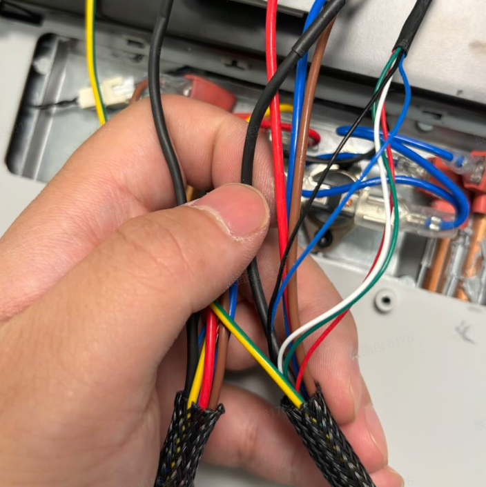 |
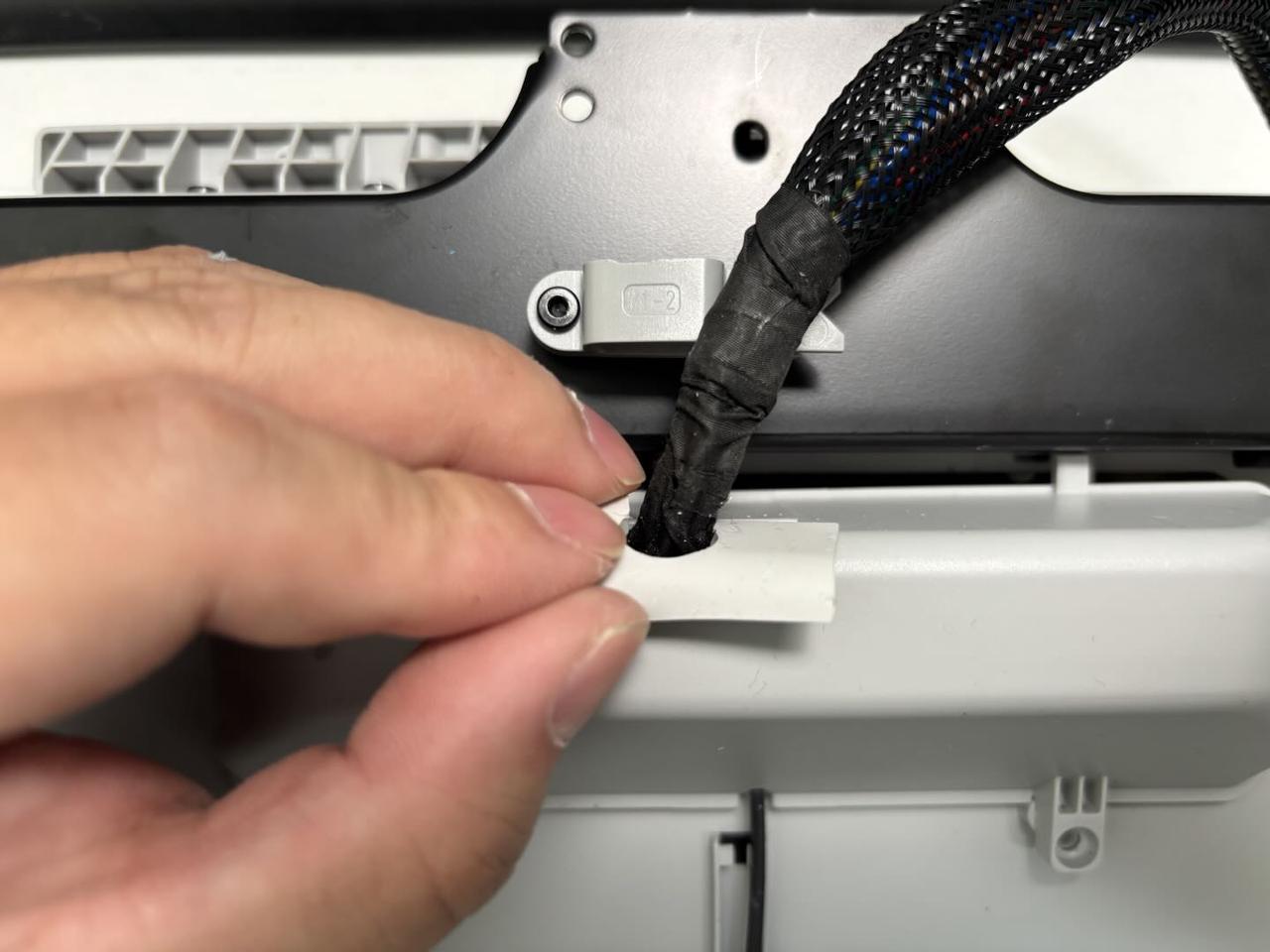
- Remove the nozzle offset calibration sensor connector from the heatbed cable clips. Since 3 clips are blocked, you can remove the cable from the two clips near the edges first, then use an Allen key to assist in removing the cable from the middle clip. Push the sleeve to make it easier to remove the cable, as shown in the image below, then take the nozzle offset calibration sensor connector out of the sleeve.
 |
 |
¶ Install the Nozzle Offset Calibration Sensor Connector
¶ Step 1: Connect the nozzle offset calibration sensor connector
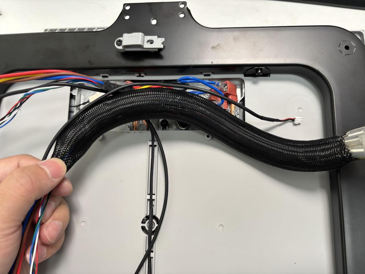
- Push the sleeve first to facilitate threading the new connector through it, as shown in the image below. Then, secure the cable into the heatbed cable clips. Use an Allen key to assist in pressing the cable into place, and reapply the tape at both ends of the sleeve.
Note: Avoid using excessive force with the Allen key to prevent damaging the cable.
 |
 |
- Thread the heatbed cable cover over the cable (the cable must be secured in the clips on the cable cover), align the screw holes, and tighten the two cable cover fixing screws (BT3x8) using an H2.0 Allen key. Then, clip the cable into the cable clip and tighten the clip fixing screw (ST3x12) using an H2.0 Allen key. Finally, insert the silicone piece into the heatbed cable cover.
¶ Step 2: Install the heatbed
Please refer to the steps available in the H2D Headbed Replacement Guide to reinstall the heatbed and nozzle offset calibration sensor.
¶ Verify the Functionality
Connect the power and turn on the printer. Initiate a print job, and if no errors occur, the replacement is successful.
¶ Screw Specification List
The following list details the specifications and quantities of screws required for replacing the H2D nozzle offset calibration sensor. This reference is provided to assist you in identifying and managing the screws during the process. It is recommended to carefully store the removed screws to prevent loss:
| Specification | Use | Position | Quantity | |
|---|---|---|---|---|
| BT3x8 | Fix the rear panel (marked by the green square) |  |
12 | |
| Fix the purge chute | 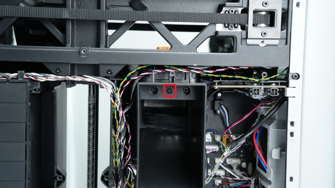 |
1 | ||
| Fix the AC board cover | 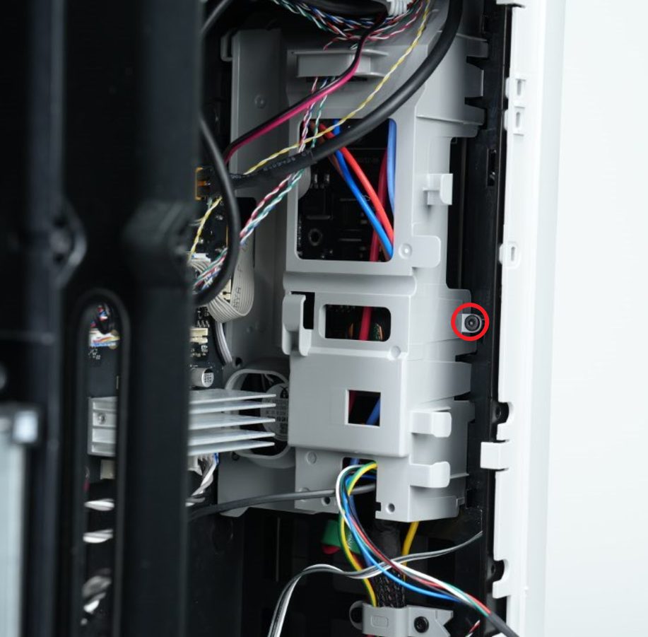 |
1 | ||
| ST3x8 | Fix the rear panel (marked by the red circle) |  |
11 | |
| ST3x12 | Fix the spool holder (marked by the yellow square) | 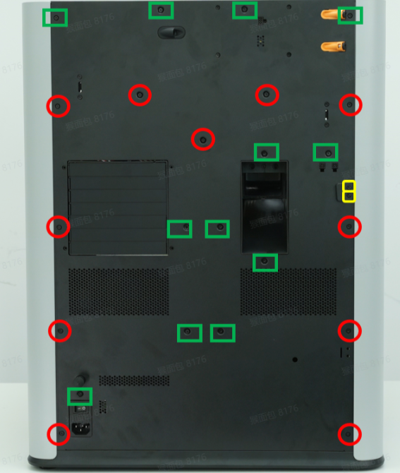 |
2 | |
| BT3x12 | Fix the cable clip | 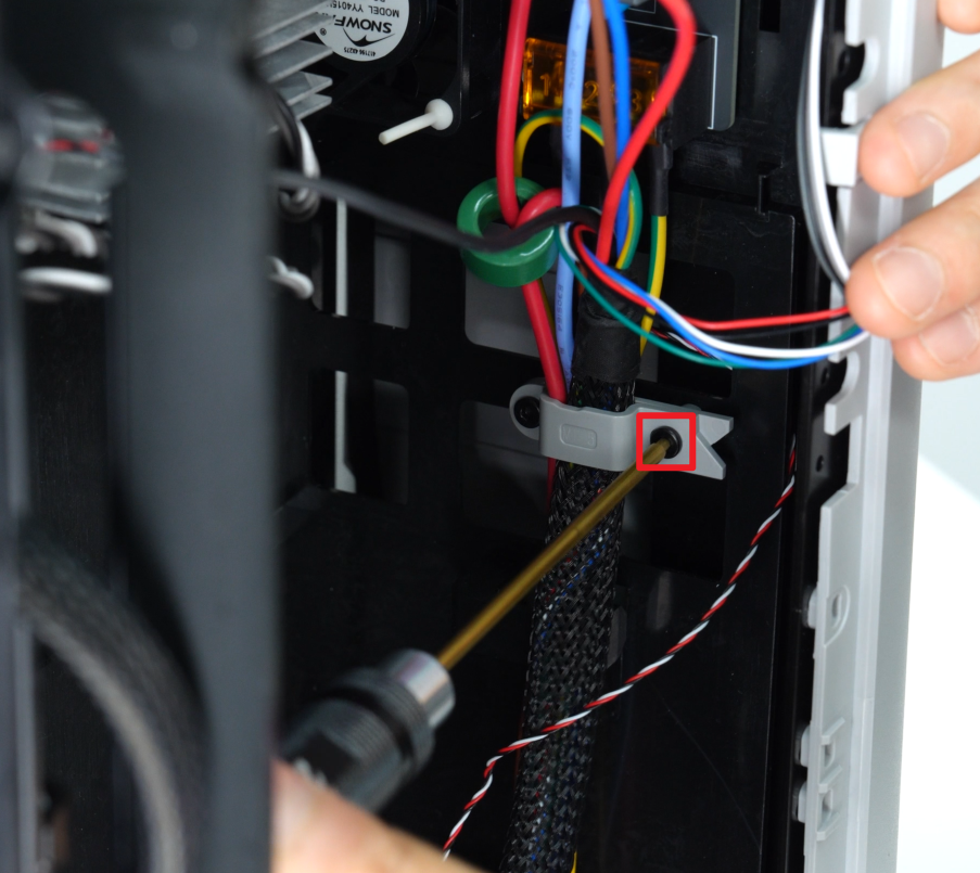 |
1 | |
| STW3x5 | Fix the ground wire | 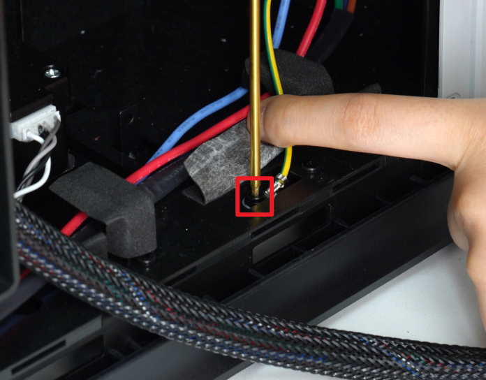 |
1 | |
| M2x5 | Fix the nozzle offset calibration coil |  |
2 | |
| M3x6 | Fix the heatbed | 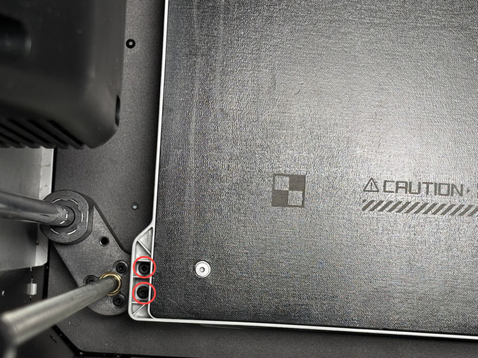 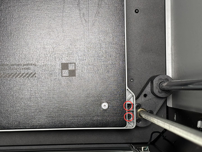 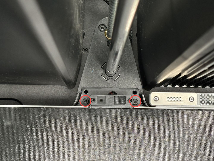 |
6 | |
| M3x35x8 | Fix the Z-axis slider | 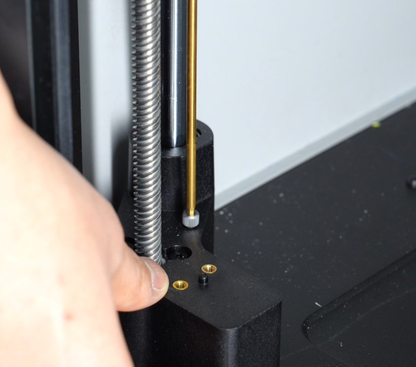 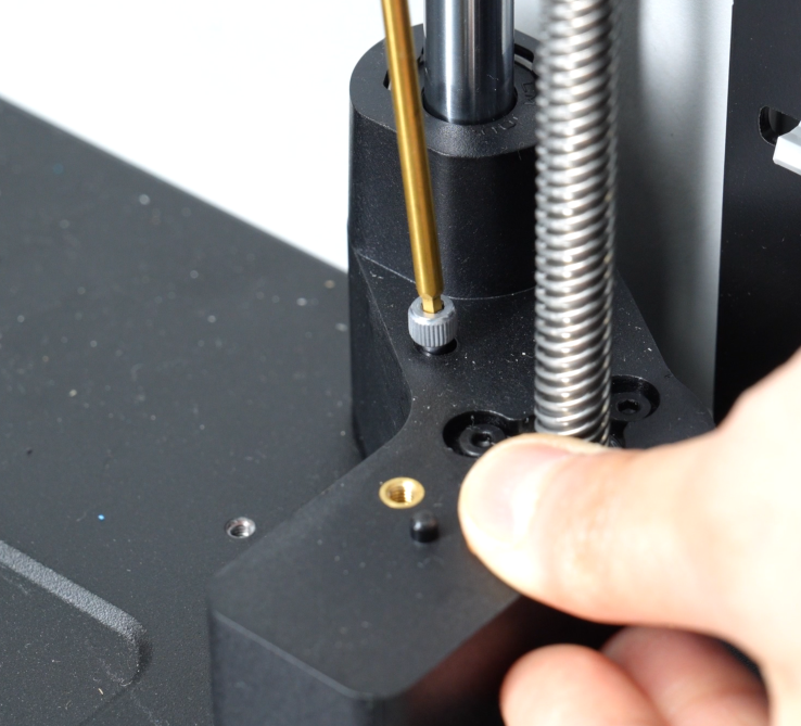 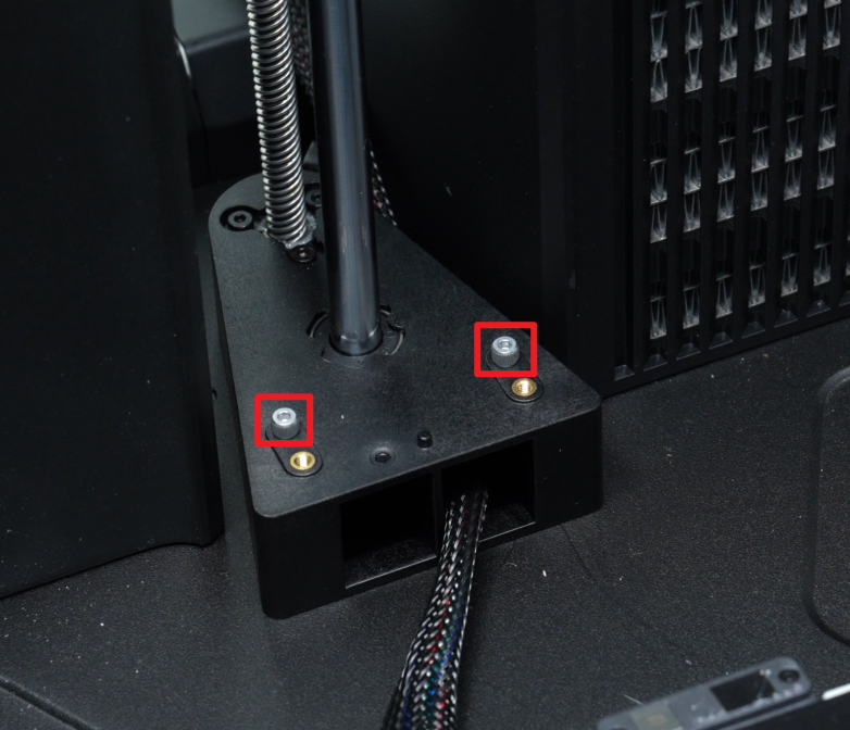 |
4 |
¶ End Notes
We hope the detailed guide provided has been helpful and informative.
If this guide does not solve your problem, please submit a technical ticket, we will answer your questions and provide assistance.
If you have any suggestions or feedback on this Wiki, please leave a message in the comment area. Thank you for your support and attention!