¶ Important Reminder
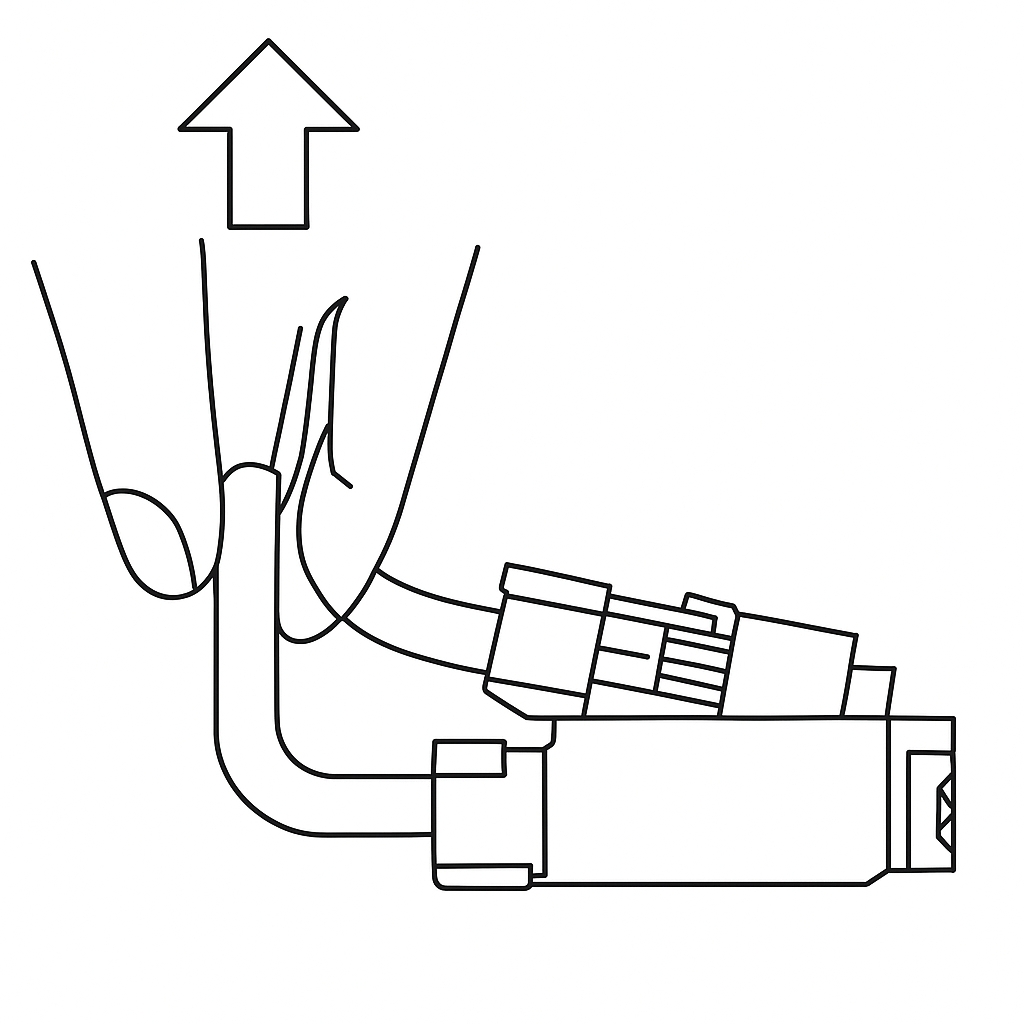
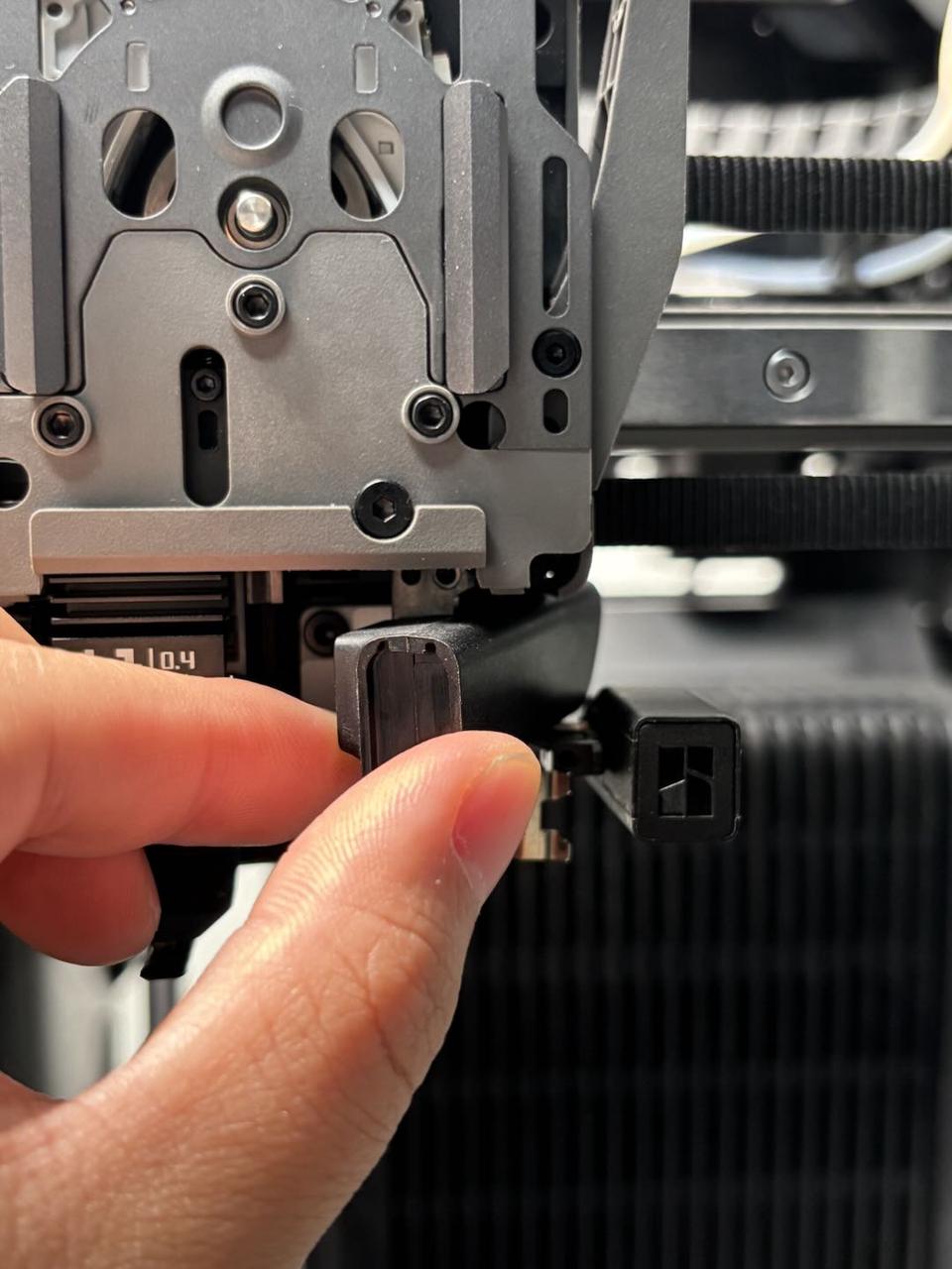
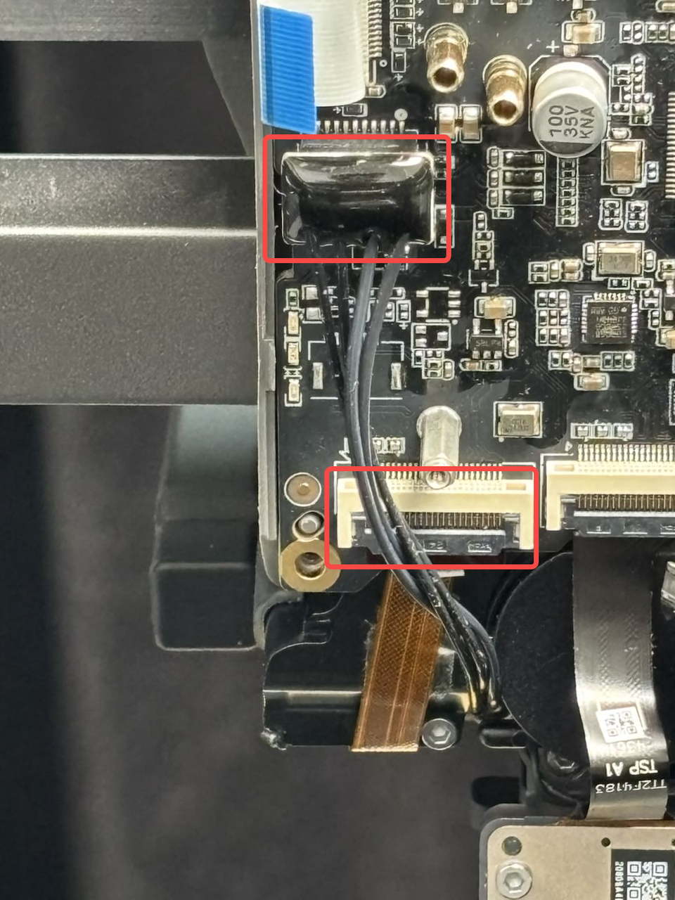
The part cooling fan connectors on the H2D feature this compact connector design. When removing the connector, please hold the base of the connector with your hand and lift straight up, perpendicular to the PCB surface, to unlock it. Never apply force in the horizontal direction to avoid damaging the connector.
¶ Toolhead Camera
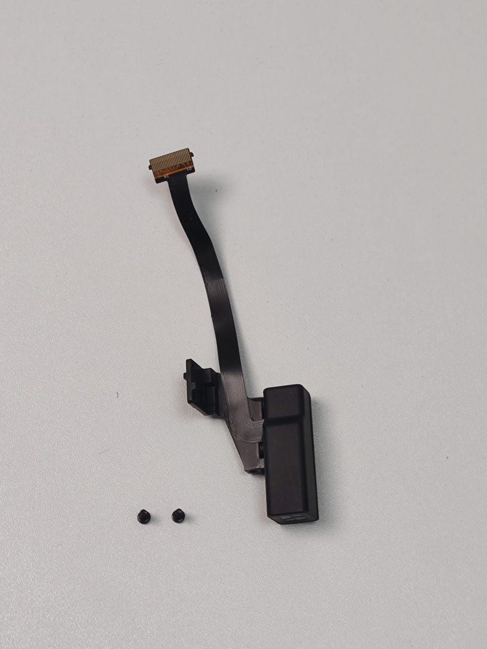
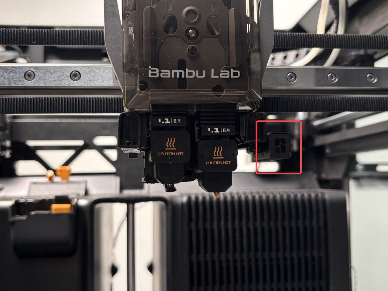
The toolhead camera (1080p 30fps) is installed on the right side of the toolhead. It can be used for motion accuracy calibration, high-precision nozzle offset calibration, build plate and laser platform identification code recognition. The toolhead camera and accessories included:
-
Toolhead camera × 1
-
M2×5 screws × 2
¶ Tools and materials needed
- New toolhead camera
-
H2.0 Allen key
-
H1.5 Allen key
Specifications and quantities of screws involved in replacing the H2D toolhead camera (it is recommended to keep the removed screws properly to avoid loss):
| Specification&##x20; | Image | Use | Position | Quantity | |
|---|---|---|---|---|---|
| M2x5 | Fix the right hotend cooling fan air duct | 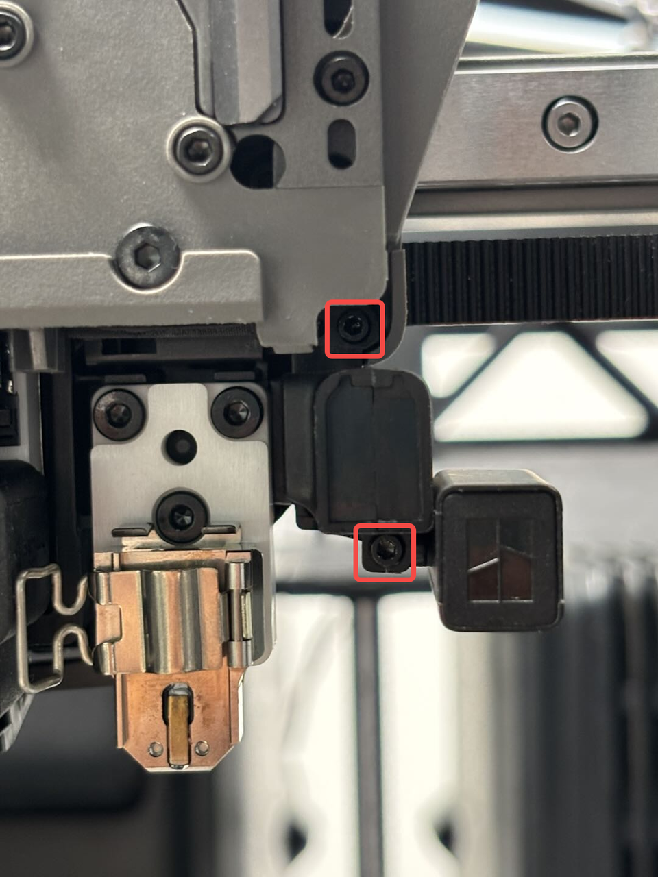 |
2 | ||
| Fix the toolhead camera bracket |  |
2 |
¶ Safety Warning
IMPORTANT!
It's crucial to power off the printer before conducting any maintenance work, including work on the printer's electronics and tool head wires. Performing tasks with the printer on can result in a short circuit, leading to electronic damage and safety hazards.
During maintenance or troubleshooting, you may need to disassemble parts, including the hotend. This exposes wires and electrical components that could short circuit if they contact each other, other metal, or electronic components while the printer is still on. This can result in damage to the printer's electronics and additional issues.
Therefore, it's crucial to turn off the printer and disconnect it from the power source before conducting any maintenance. This prevents short circuits or damage to the printer's electronics, ensuring safe and effective maintenance. For any concerns or questions about following this guide, we recommend submitting a technical ticket regarding your issue and we will do our best to respond promptly and provide the assistance you need.
¶ Remove the Toolhead Camera
¶ Step 1: Remove the part cooling fan air duct, fan and extruder connection board
You can refer to this Wiki to remove the following in order:
-
Part cooling fan air duct
-
Part cooling fan
- Extruder connection board
Remove the Extruder Connection Board/TH Board/FPC Cable
¶ Step 2: Remove the right hotend cooling fan air duct
First remove the toolhead front cover and the right hotend, then use an H1.5 Allen key to remove the 2 fixing screws (M2x5), and pull the right hotend fan air duct out of the toolhead at an angle.

¶ Step 3: Remove the toolhead camera
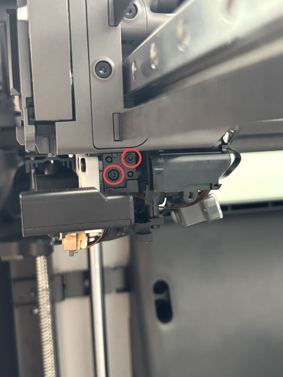
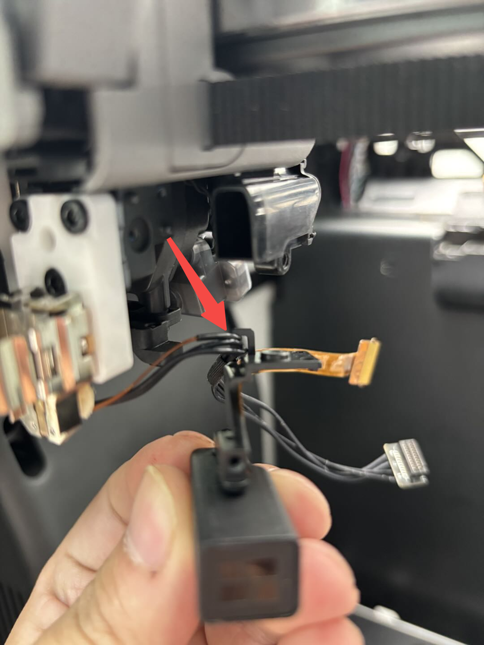
First, unplug the right hotend heating assembly connector from the TH board on the toolhead, unfasten the buckle on the toolhead camera cable, and pull the cable out of the interface. Then use an H1.5 Allen key to remove the 2 toolhead camera bracket fixing screws (M2x5), remove the right hotend heating assembly connector from the buckle on the toolhead camera, and remove the toolhead camera.

¶ Install the Toolhead Camera
¶ Step 1: Install the toolhead camera
Insert the right hotend heating assembly connector into the cable buckle of the toolhead camera, then align the toolhead camera bracket with the screw hole, and use an H1.5 Allen key to tighten the two toolhead bracket fixing screws (M2x5); insert the toolhead camera connector into the connector and make sure to buckle it after aligning it. Then align the right hotend heating assembly with the plug on the TH board and re-insert the cable.


¶ Step 2: Install the right hotend cooling fan air duct
Insert the right hotend cooling fan air duct into the toolhead at an angle, and tighten the 2 fixing screws (M2x5) with an H1.5 Allen key; then install the right hotend into the right hotend heating assembly, fasten the buckle, and then install the silicone sock for hotend.


¶ Step 3: Install the extruder connection board, part cooling fan and air duct
You can refer to this Wiki to install the following in order:
-
Extruder connection board
-
Part cooling fan
-
Part cooling fan air duct
Remove the Extruder Connection Board/TH Board/FPC Cable
¶ Verify the Functionality
Connect the power supply and turn on the printer. The error message disappears.
¶ End Notes
We hope the detailed guide provided has been helpful and informative.
If this guide does not solve your problem, please submit a technical ticket, we will answer your questions and provide assistance.
If you have any suggestions or feedback on this Wiki, please leave a message in the comment area. Thank you for your support and attention!