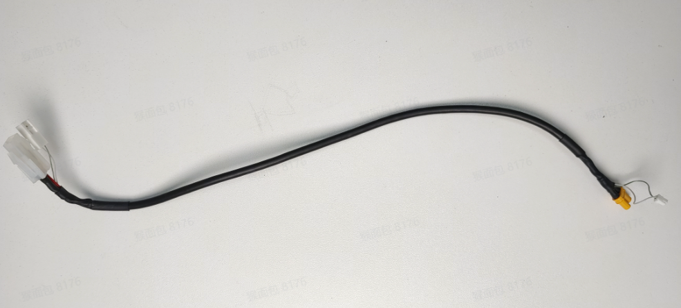
¶ Toolhead to MC Board Cable
The toolhead to MC board cable is connected to the MC board and extends to the vicinity of the filament buffer, where the cable on the TH board is connected to the toolhead to MC board cable.
The spare parts of Toolhead to MC Board Cable include the following:&##x20;
- Toolhead to MC Board Cable * 1
¶ Tools and materials needed
-
Toolhead to MC Board Cable
-
H2.0 Allen key
Specifications and quantities of screws required to replace the H2D Toolhead to MC Board Cable (it is recommended to keep the removed screws properly to avoid loss):
| Specification&##x20; | Image | Use | Position | Quantity | |
|---|---|---|---|---|---|
| BT3x8 | Fix the rear panel |  |
12 | ||
| Fix the purge chute | 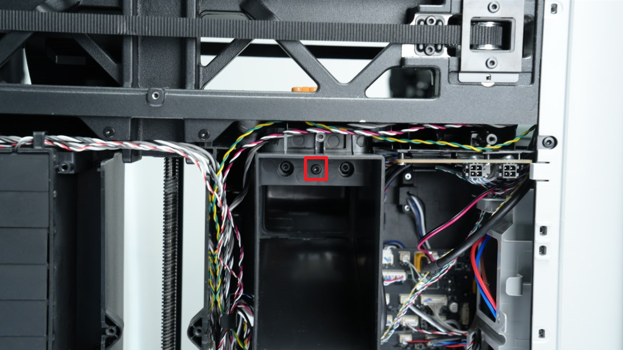 |
1 | |||
| ST3x6 | Fix the rear panel | 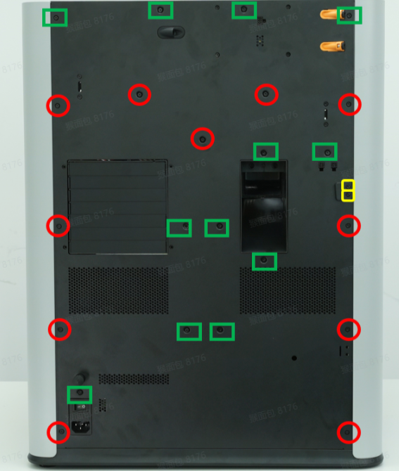 |
11 | ||
| ST3x12 | Fix the spool holder bracket |  |
2 | ||
| BT2.6x8 | Fix the AP board cover |  |
1 |
¶ Safety Warning
IMPORTANT!
It's crucial to power off the printer before conducting any maintenance work, including work on the printer's electronics and tool head wires. Performing tasks with the printer on can result in a short circuit, leading to electronic damage and safety hazards.
During maintenance or troubleshooting, you may need to disassemble parts, including the hotend. This exposes wires and electrical components that could short circuit if they contact each other, other metal, or electronic components while the printer is still on. This can result in damage to the printer's electronics and additional issues.
Therefore, it's crucial to turn off the printer and disconnect it from the power source before conducting any maintenance. This prevents short circuits or damage to the printer's electronics, ensuring safe and effective maintenance. For any concerns or questions about following this guide, we recommend submitting a technical ticket regarding your issue and we will do our best to respond promptly and provide the assistance you need.
¶ Remove the Toolhead to MC Board Cable
¶ Step 1: Remove the rear panel
You can refer to this Wiki to remove the H2D rear panel:
¶ Step 2: Remove the AP board cover and cable cover
- Use an H2.0 Allen key to remove 1 fixing screw (BT2.6x8), and then remove the AP board cover from the side near the front door.
- The cable cover is fixed by a clip, and you can pull the cable cover outwards.
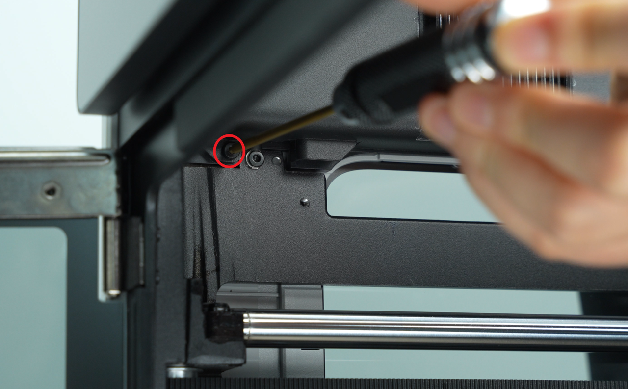
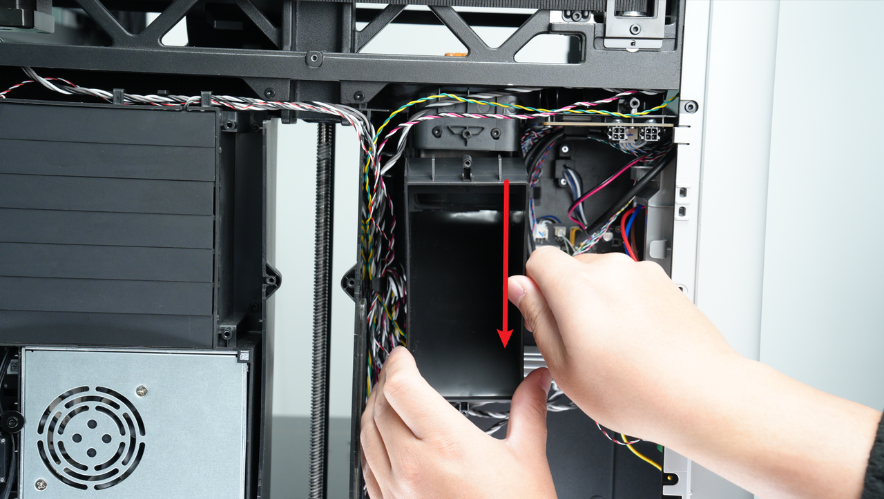
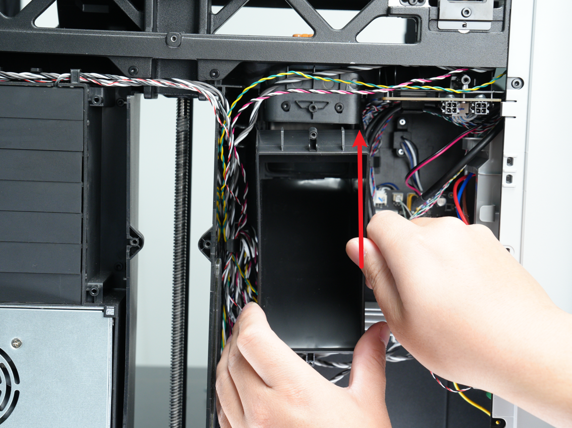
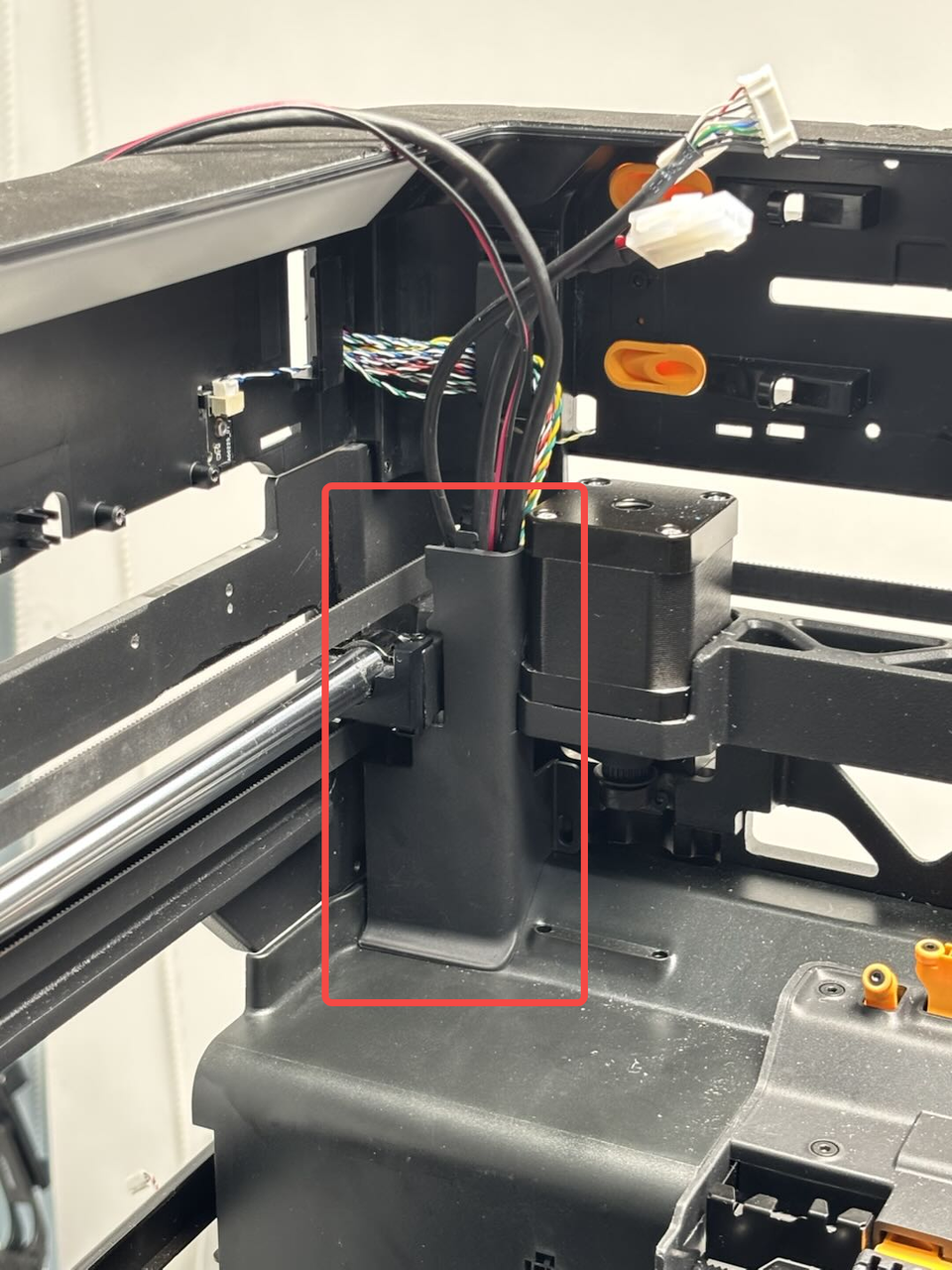
¶ Step 3: Remove the purge chute
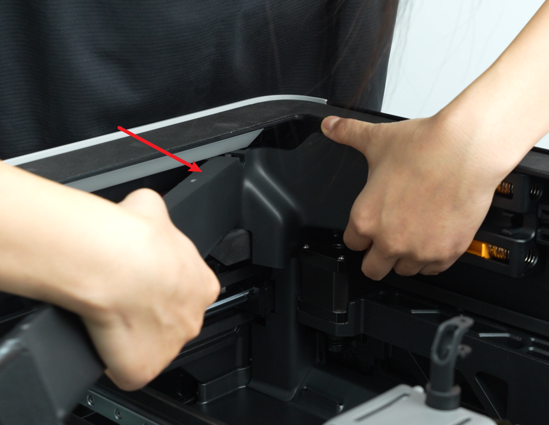
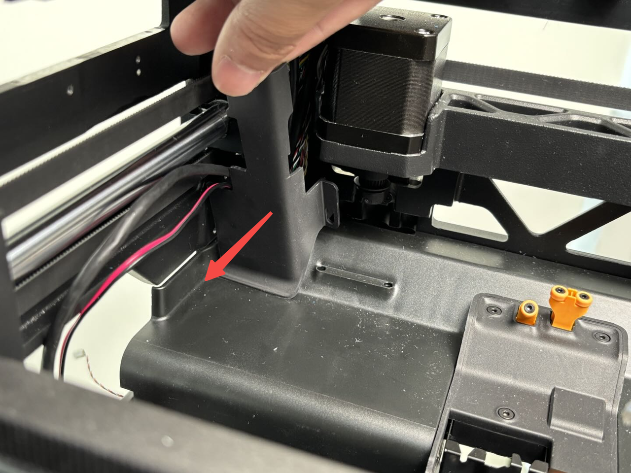
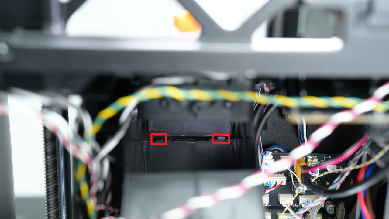
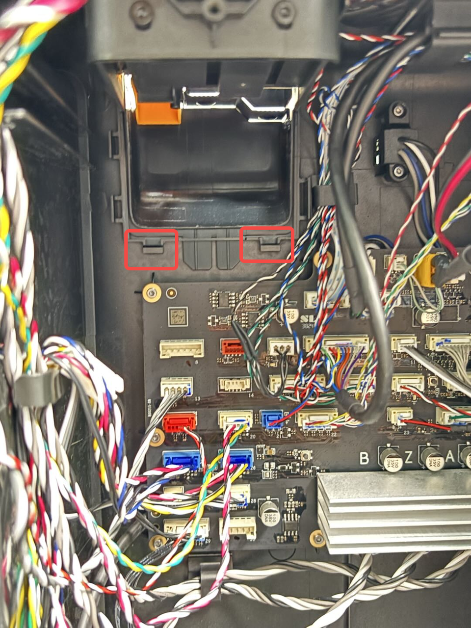
Use an H2.0 Allen key to remove one BT3x8 fixing screw, then pull the purge chute downward until its two latches become visible. Gently pull the purge chute outward to remove it.
Note: The purge chute is secured not only by the top screw but also by two bottom latches that clip into the inner frame.

¶ Step 4: Remove the toolhead to MC board cable
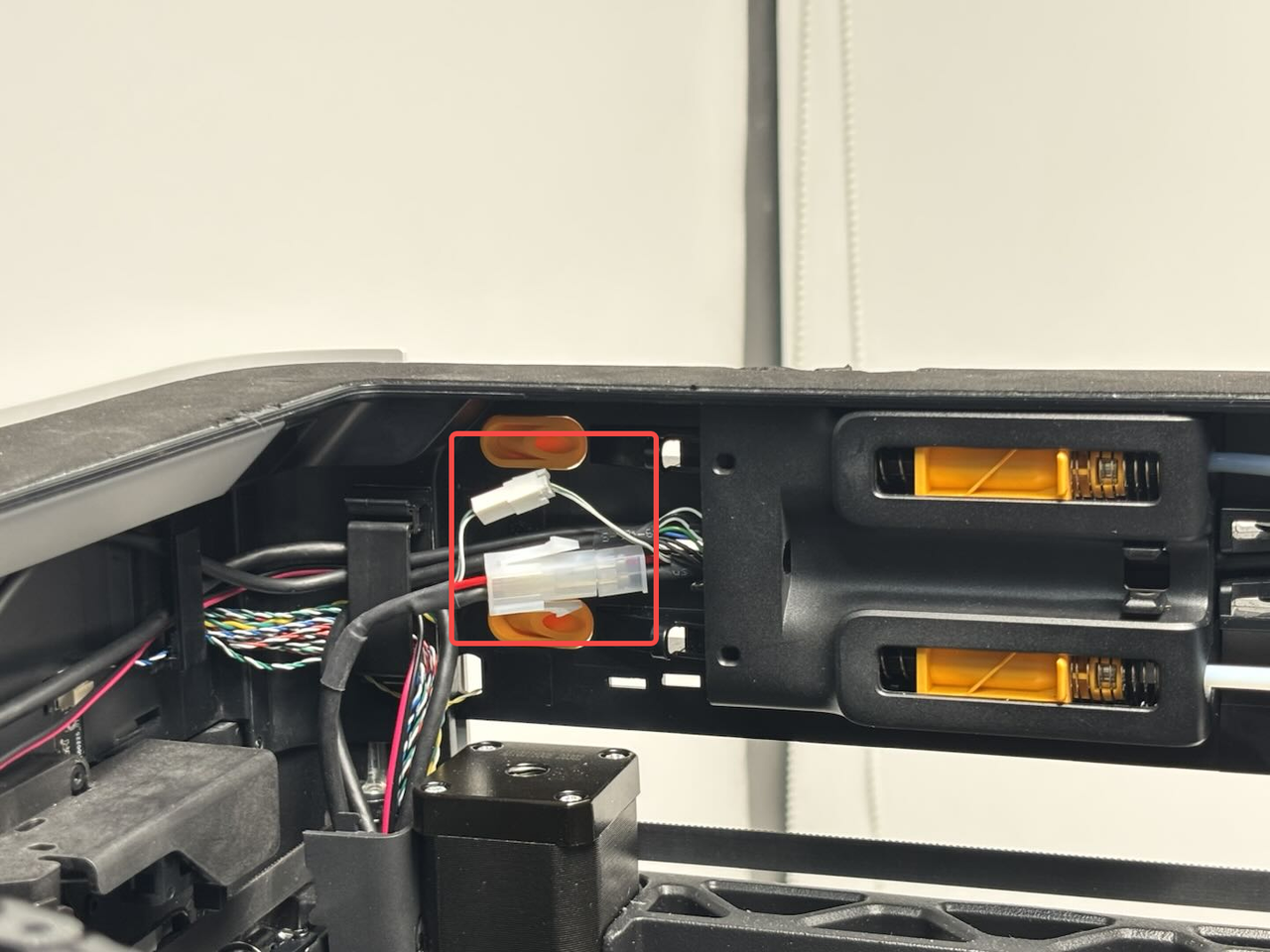
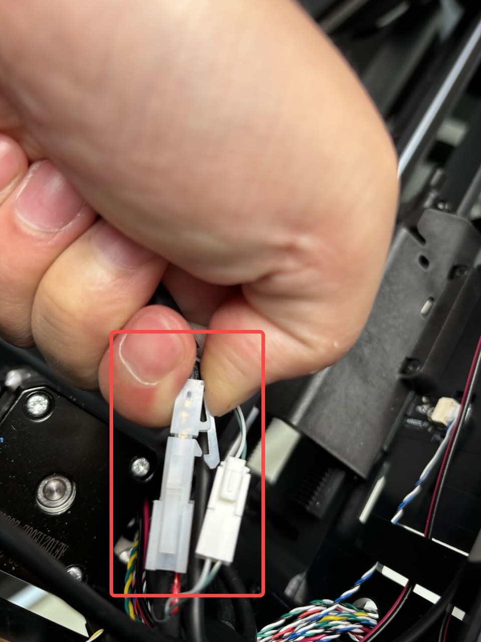
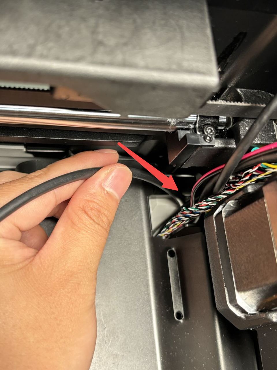
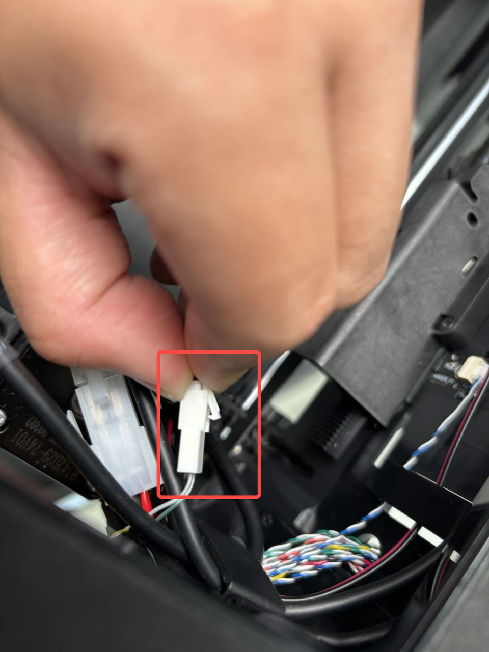
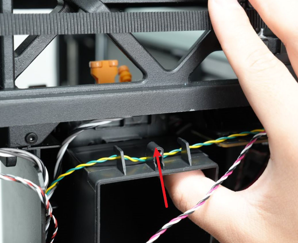
- First disconnect the cable that comes with the TH board near the buffer;
Note: You need to press the buckle according to the figure below and then disconnect the cable.

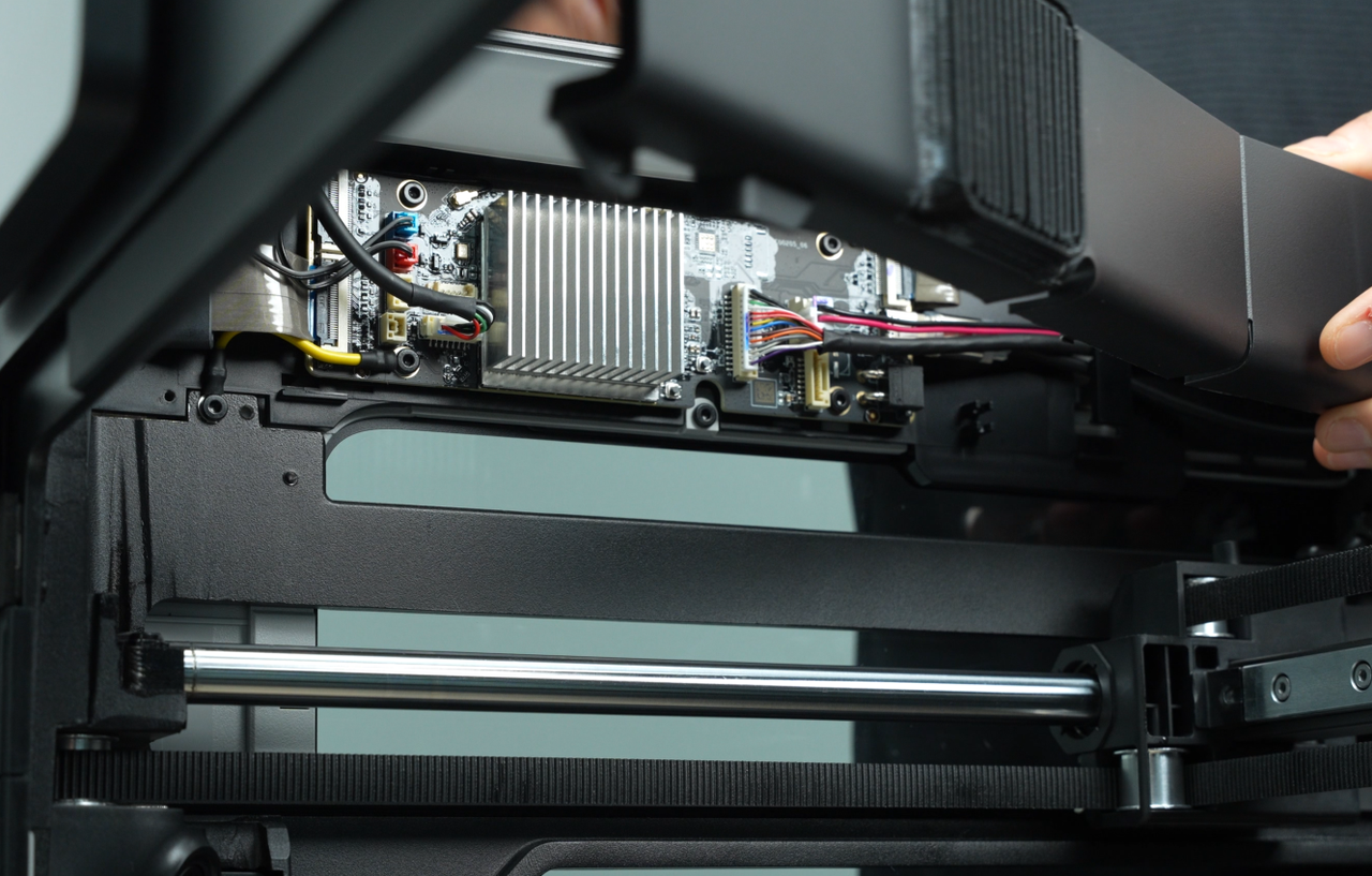
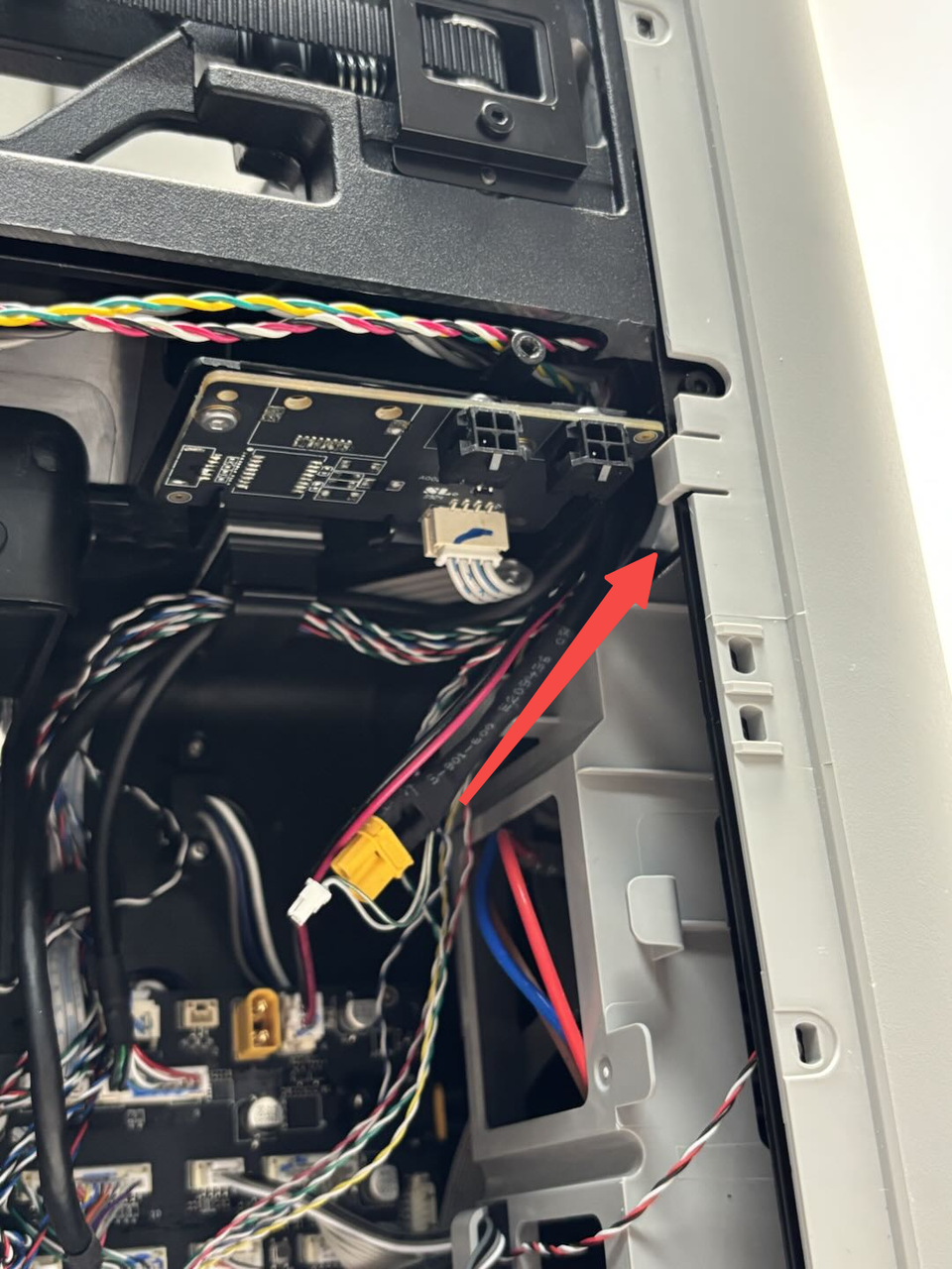
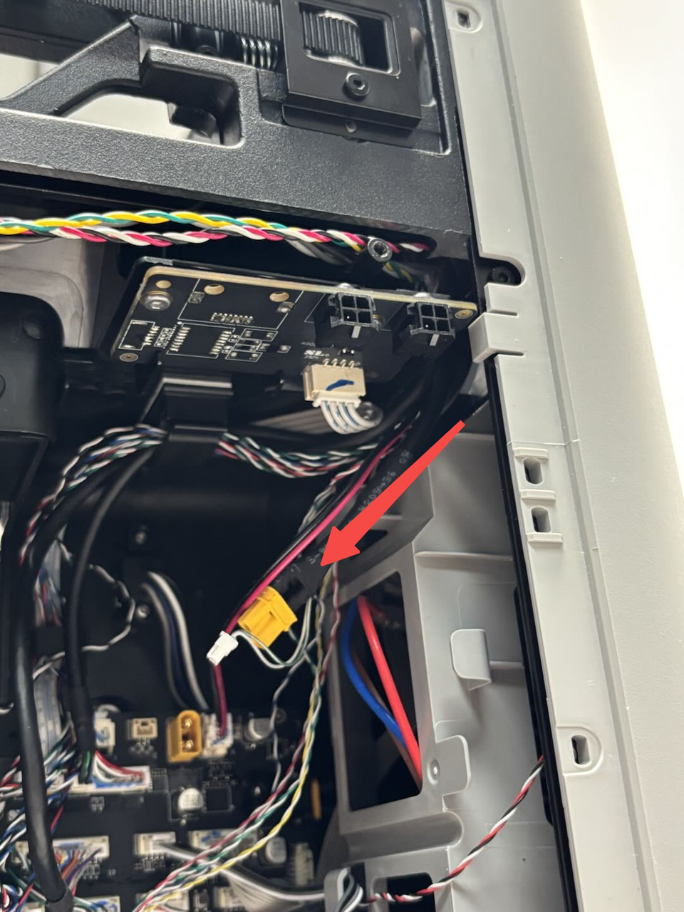
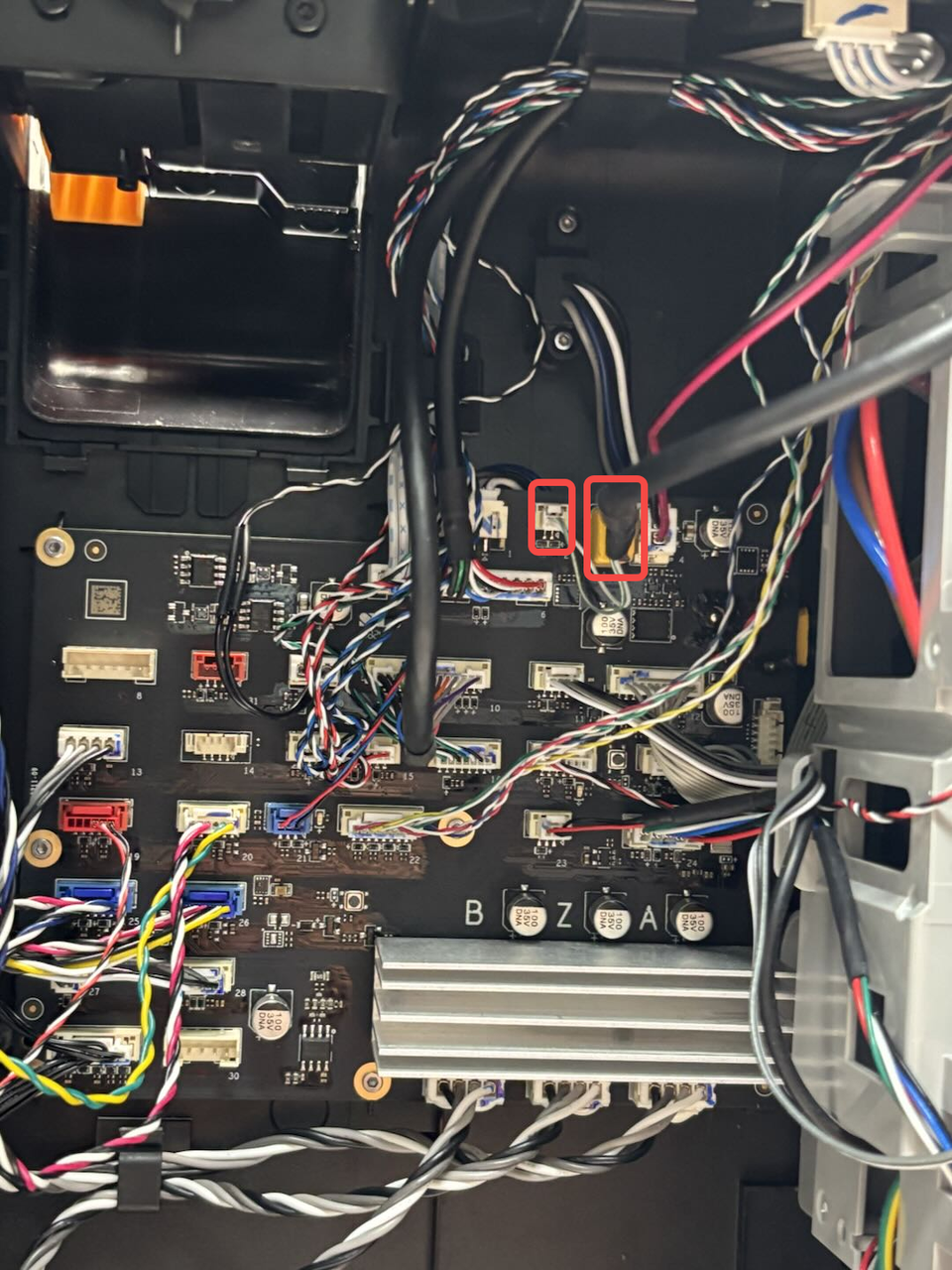
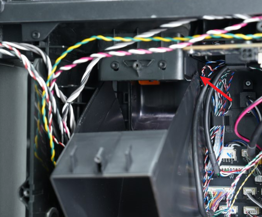
- Then disconnect the toolhead to MC board cable on the MC board, and then pull the toolhead to MC board cable out of the liner.

¶ Install the Toolhead to MC Board Cable
¶ Step 1: Install the Toolhead to MC Board Cable
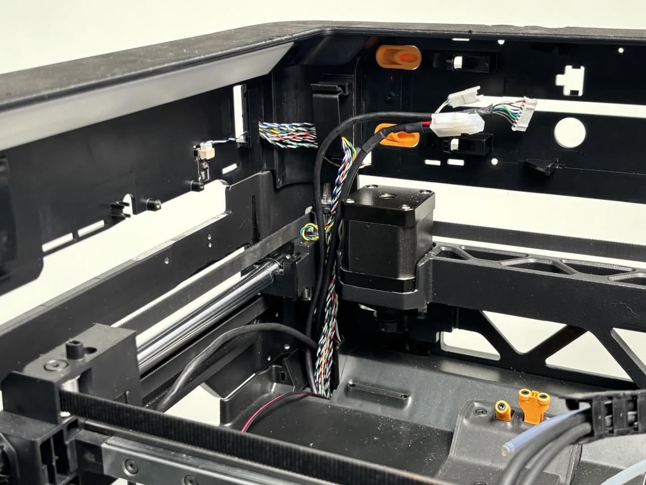
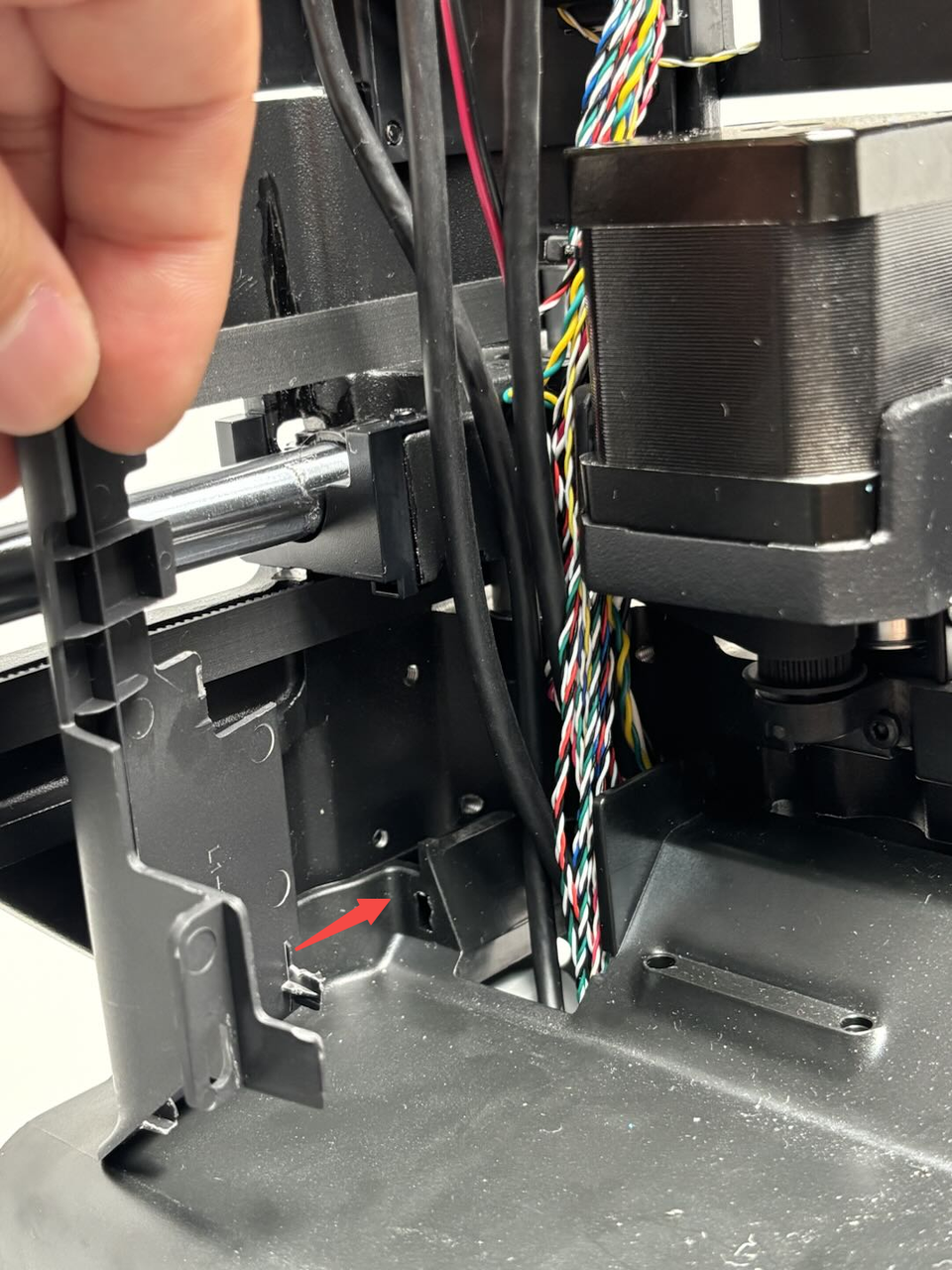
- Pass the toolhead to MC board cable through the wiring hole of the lining and then connect it to the MC board.
- Connect the cable to the cable that comes with the TH board.


¶ Step 2: Install the purge chute
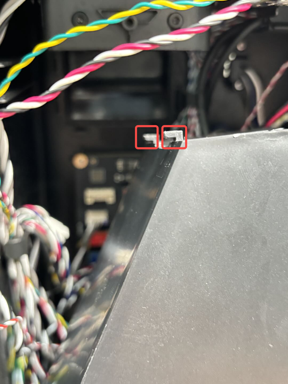
- Align the two bottom latches of the purge chute with the corresponding holes on the inner frame.
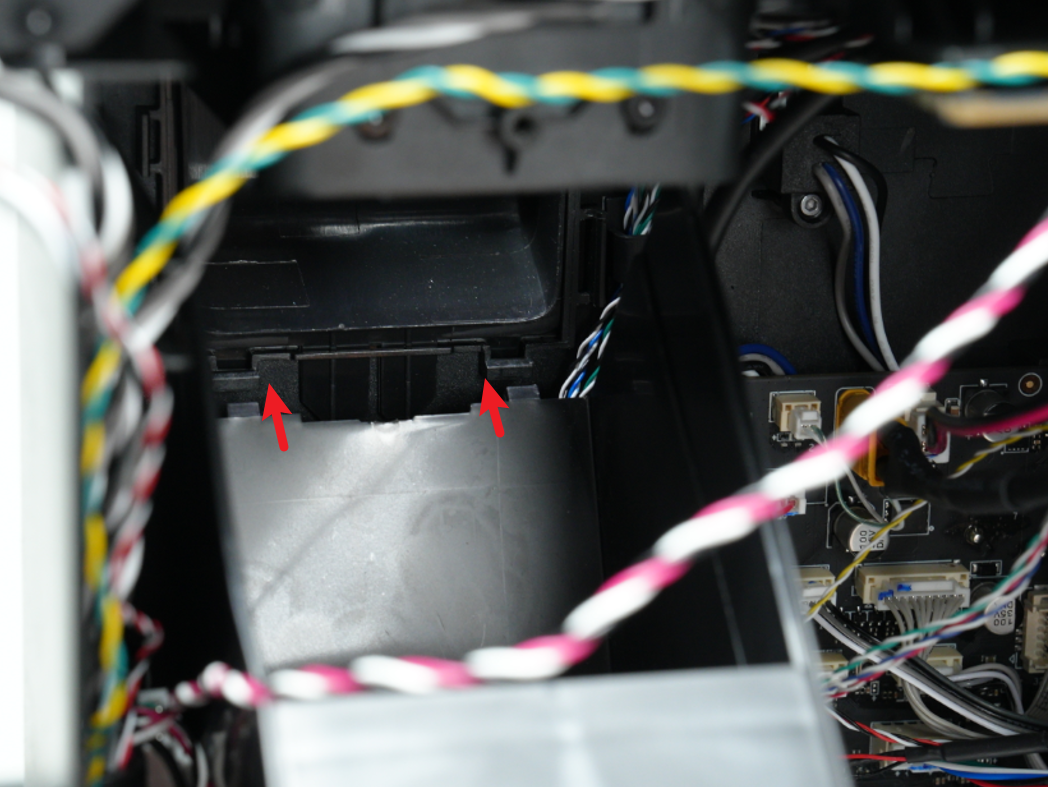
- Push the purge chute upward to ensure the bottom latches snap into the inner frame. Support the top of the purge chute with one hand and align the screw hole at the top. Then use an H2.0 Allen key to tighten one fixing screw. Secure the two cables (yellow-green and red-white) into the cable clip on the top of the purge chute.

Note: During installation, ensure the sides of the purge chute are clipped onto the outer edge of the inner frame. Clipping it onto the inner edge may prevent proper installation.
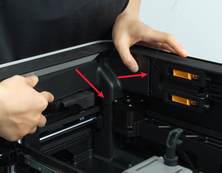
¶ Step 3: Install the AP board cover and cable cover
- Snap the cable cover into the printer;
- First, snap the AP board cover back from the side close to the back of the printer, press both arrows into place, flush with the right side of the filament buffer and the bottom with the cable cover, and then tighten a fixing screw (BT2.6x8) using an H2.0 Allen key.

¶ Step 4: Install the rear panel
You can refer to this Wiki to install the H2D rear panel:
¶ Verify the Functionality
Connect the power supply and turn on the printer, initiate printing, and ensure there is no error.
¶ End Notes
We hope the detailed guide provided has been helpful and informative.
If this guide does not solve your problem, please submit a technical ticket, we will answer your questions and provide assistance.
If you have any suggestions or feedback on this Wiki, please leave a message in the comment area. Thank you for your support and attention!