¶ Top Chamber LED and Cover
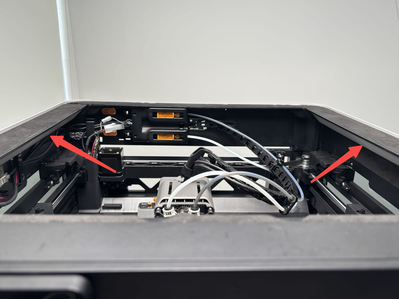
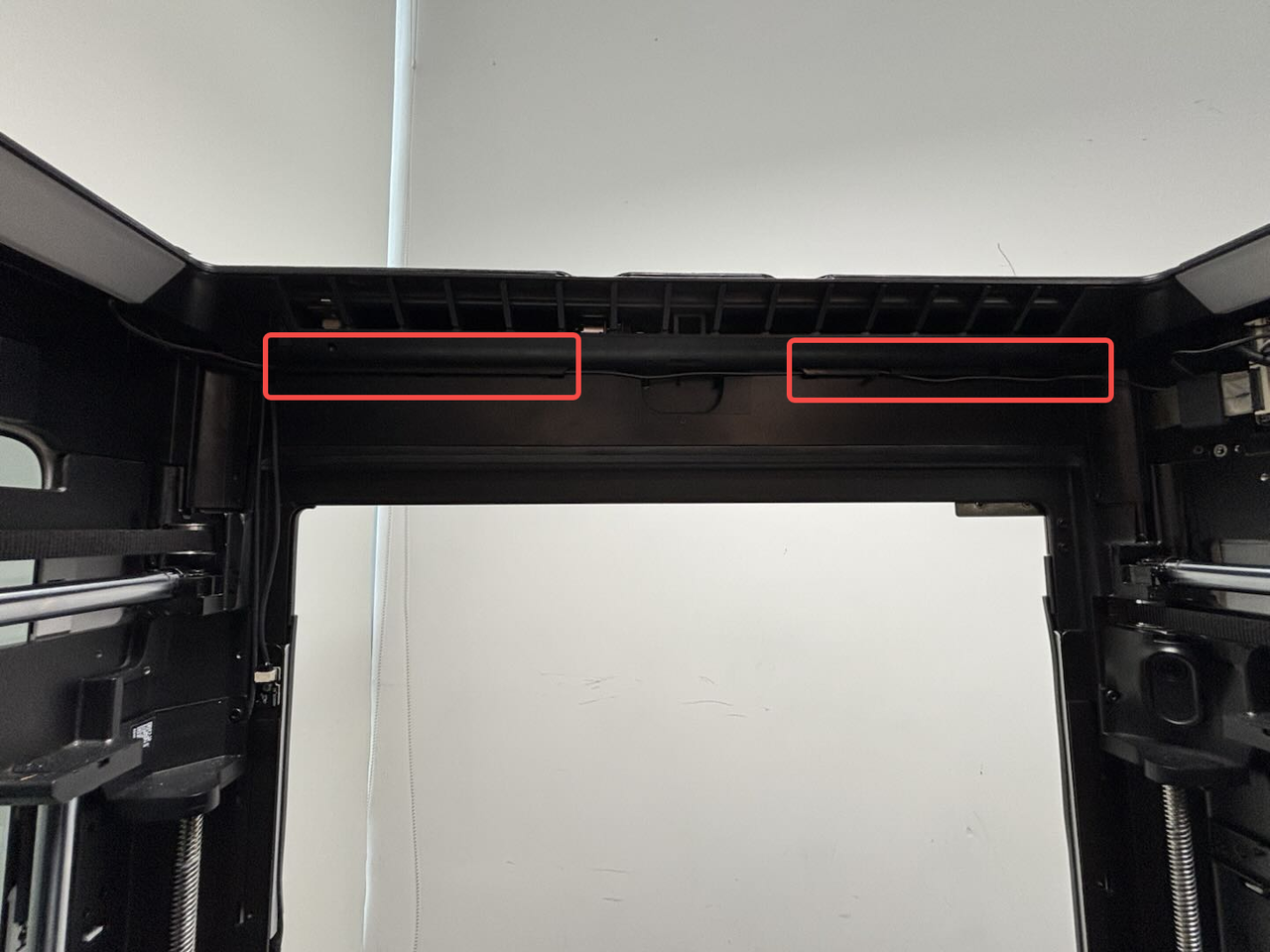
The top chamber LED is used to provide supplementary lighting for the chamber. The top chamber LEDs are installed on the left and right sides of the printer's top frame, as well as on the left and right front pillars.
The top chamber LED covers are installed on the left and right sides of the top frame.
The spare parts for the top chamber LED/cover are divided into the following 3 types:
-
Top chamber LED - left
-
Top chamber LED - right
-
Top chamber LED cover - universal (left and right)
¶ When to Use
-
The top chamber LED is burnt out;
-
The top chamber LED cable is damaged or short-circuited;
-
The top chamber LED cover is damaged.
¶ Tools and Materials Needed
-
New top chamber LED or cover
-
Flat pry tool or card
¶ Safety Warning
IMPORTANT!
It's crucial to power off the printer before conducting any maintenance work, including work on the printer's electronics and tool head wires. Performing tasks with the printer on can result in a short circuit, leading to electronic damage and safety hazards.
During maintenance or troubleshooting, you may need to disassemble parts, including the hotend. This exposes wires and electrical components that could short circuit if they contact each other, other metal, or electronic components while the printer is still on. This can result in damage to the printer's electronics and additional issues.
Therefore, it's crucial to turn off the printer and disconnect it from the power source before conducting any maintenance. This prevents short circuits or damage to the printer's electronics, ensuring safe and effective maintenance. For any concerns or questions about following this guide, we recommend submitting a technical ticket regarding your issue and we will do our best to respond promptly and provide the assistance you need.
¶ Replace the Right Top Chamber LED and Cover
¶ Remove the Right Top Chamber LED
¶ Step 1: Remove the top chamber LED cover
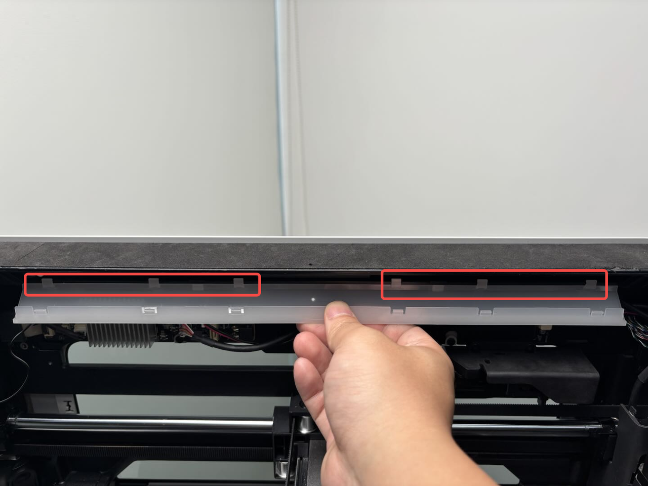
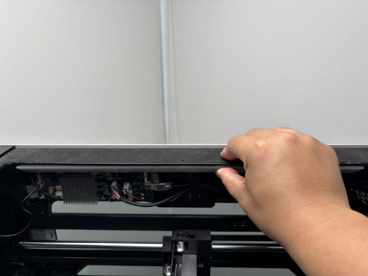
The top chamber LED cover is secured to the upper frame of the printer with clips. Use a flat pry tool or card to insert between the upper frame and the LED cover, then pry it off.
If you are only replacing the top chamber LED cover, you do not need to follow the subsequent steps.

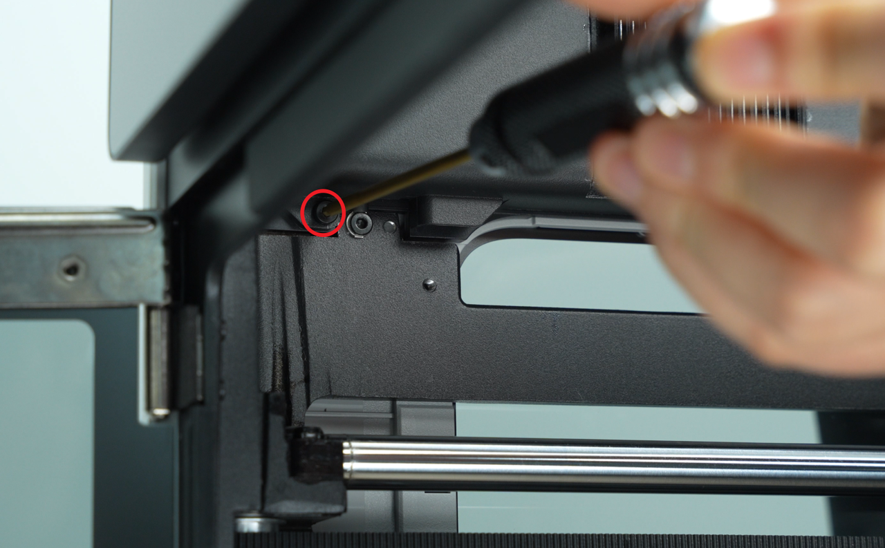
¶ Step 2: Remove the AP board cover
Use an H2.0 Allen key to unscrew one fixing screw (BT2.6x8), then remove the AP board cover from the side near the front door.


If your printer is H2D Laser Version, please follow this extra step:
Step 3: Remove the birdseye camera
The cable of the right LED is pressed under the birdseye camera, so you need to remove the birdseye camera first.
Refer to this Wiki for removing the birdseye camera:
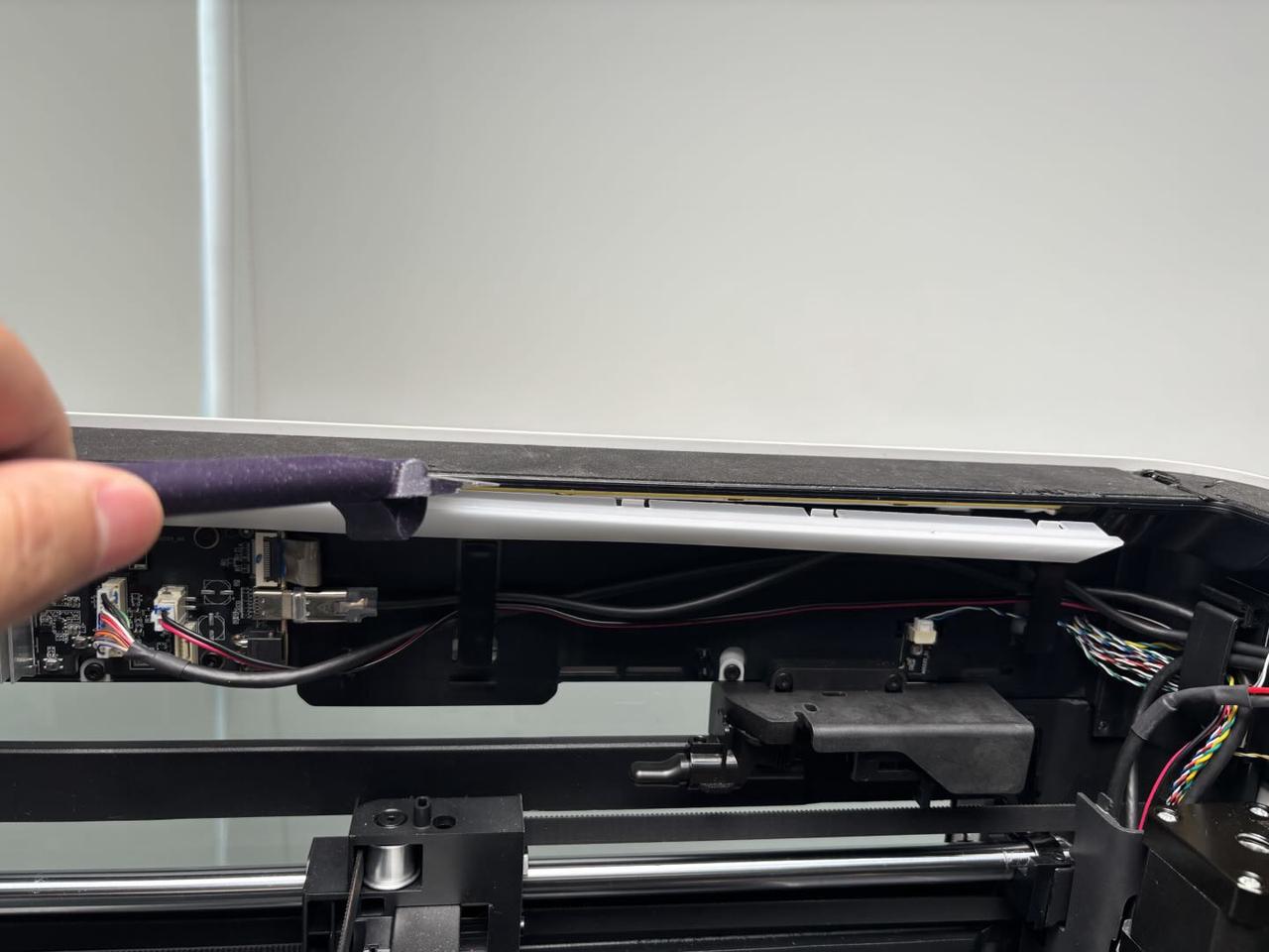
¶ Step 3: Remove the top chamber LED
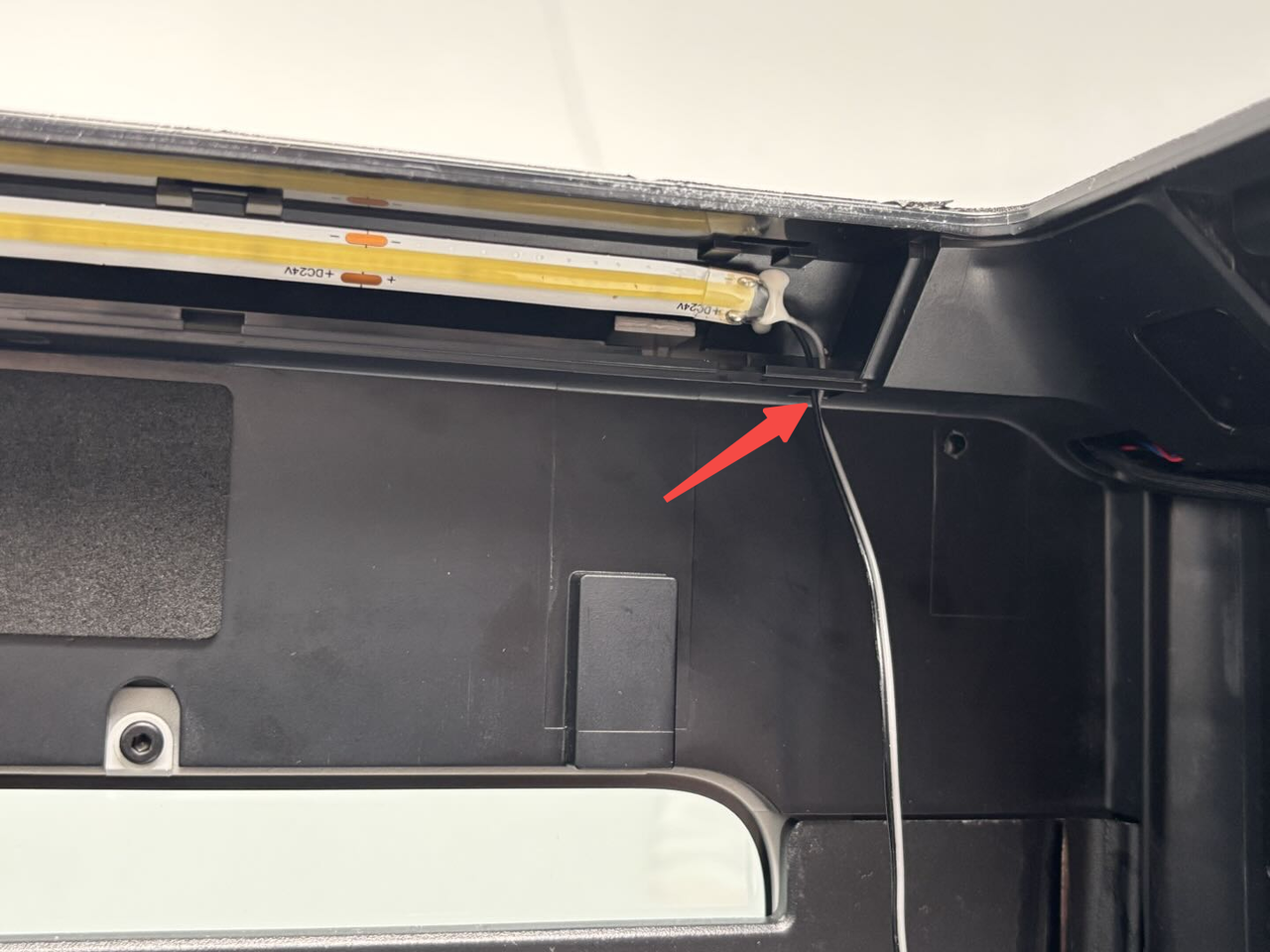
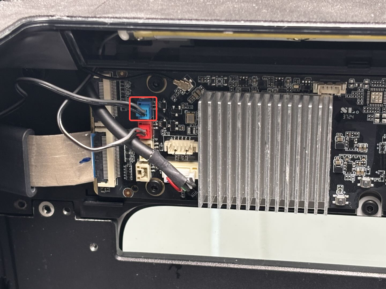
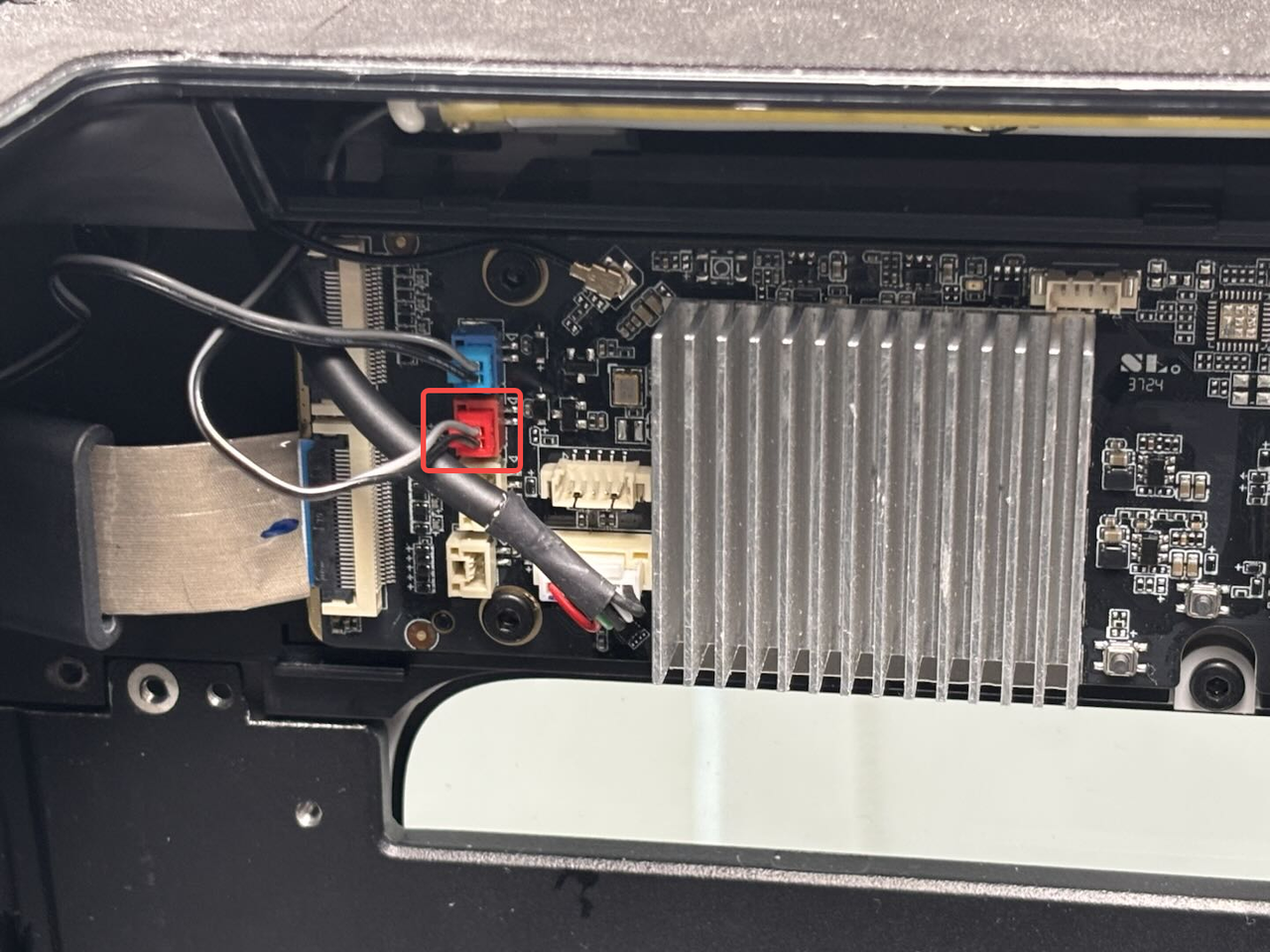
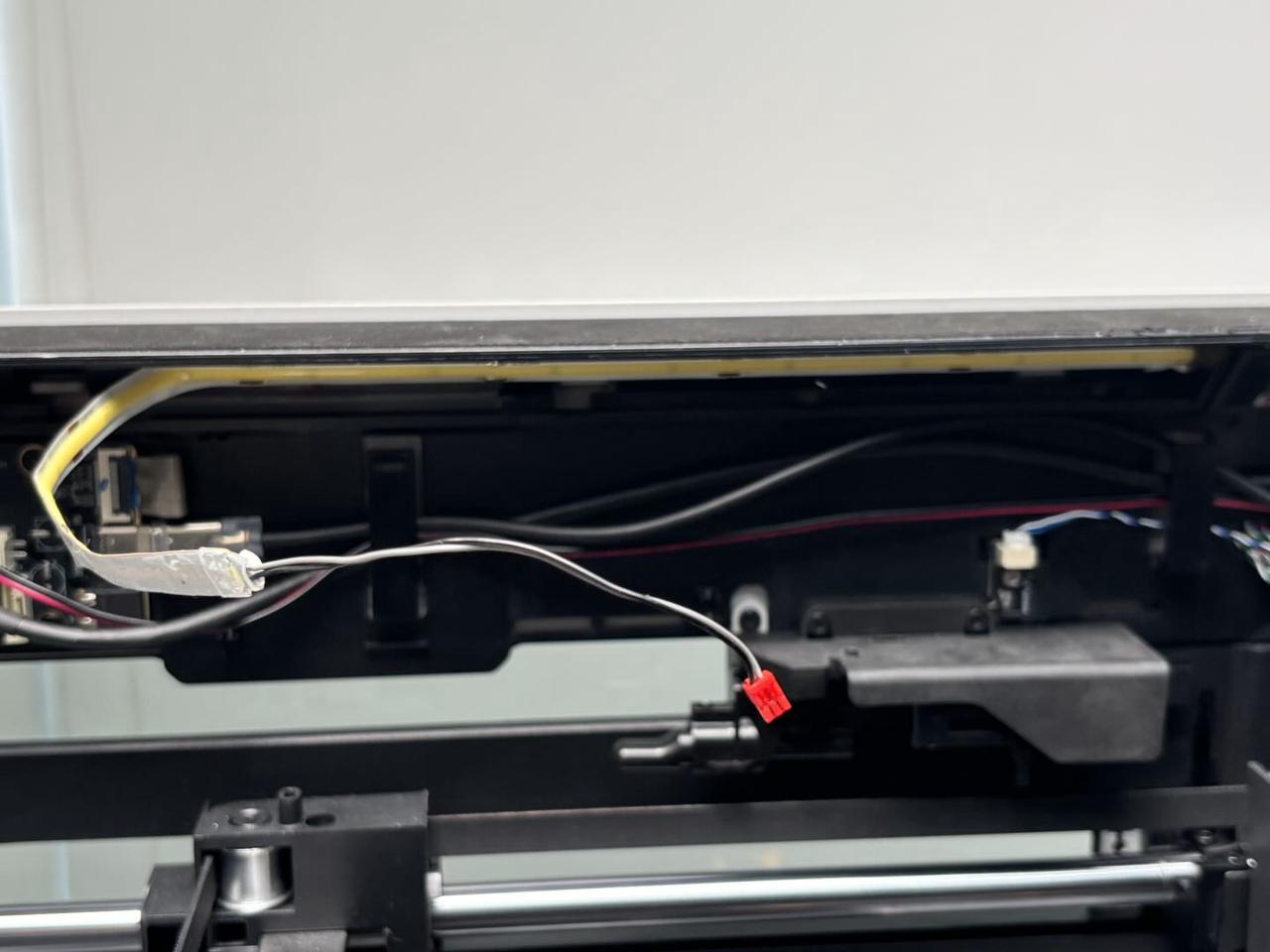
- Press the clip (on the left side) to disconnect the top chamber LED cable from the AP board, pull the cable out of the cable channel, and thread the cable through the small hole in the upper frame.


- Peel off the top chamber LED to remove it.
¶ Install the Right Top Chamber LED
¶ Step 1: Install the top chamber LED
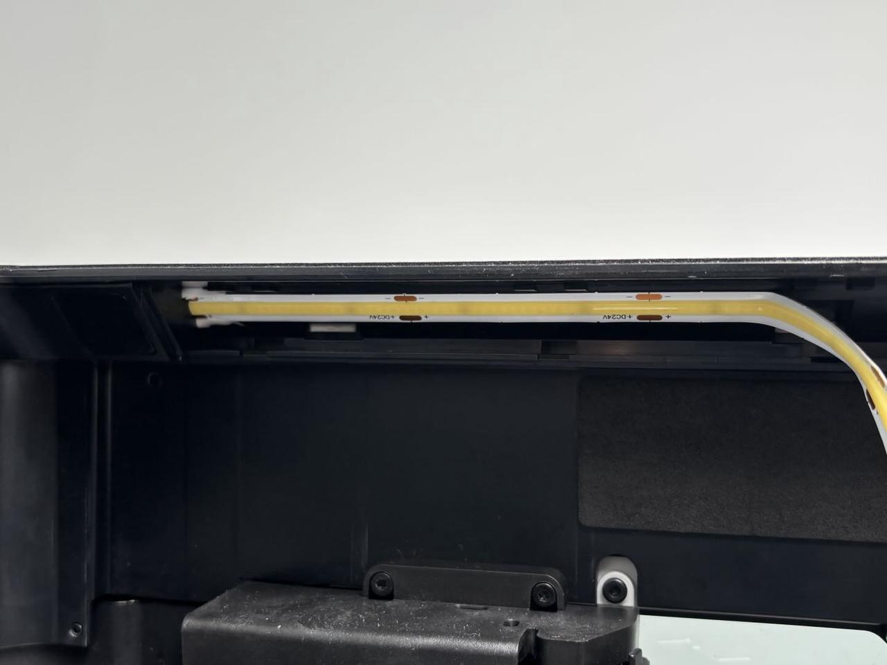
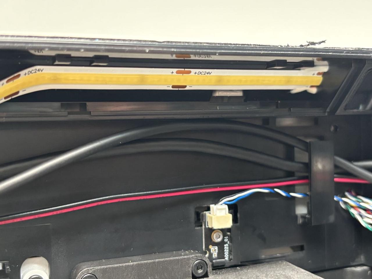
- Peel off the backing of the new top chamber LED, align the end of the LED (the end without the connector) to the left side, and stick it back.
No need to apply white glue to both ends of the top chamber LED, just make sure it is tightly adhered.
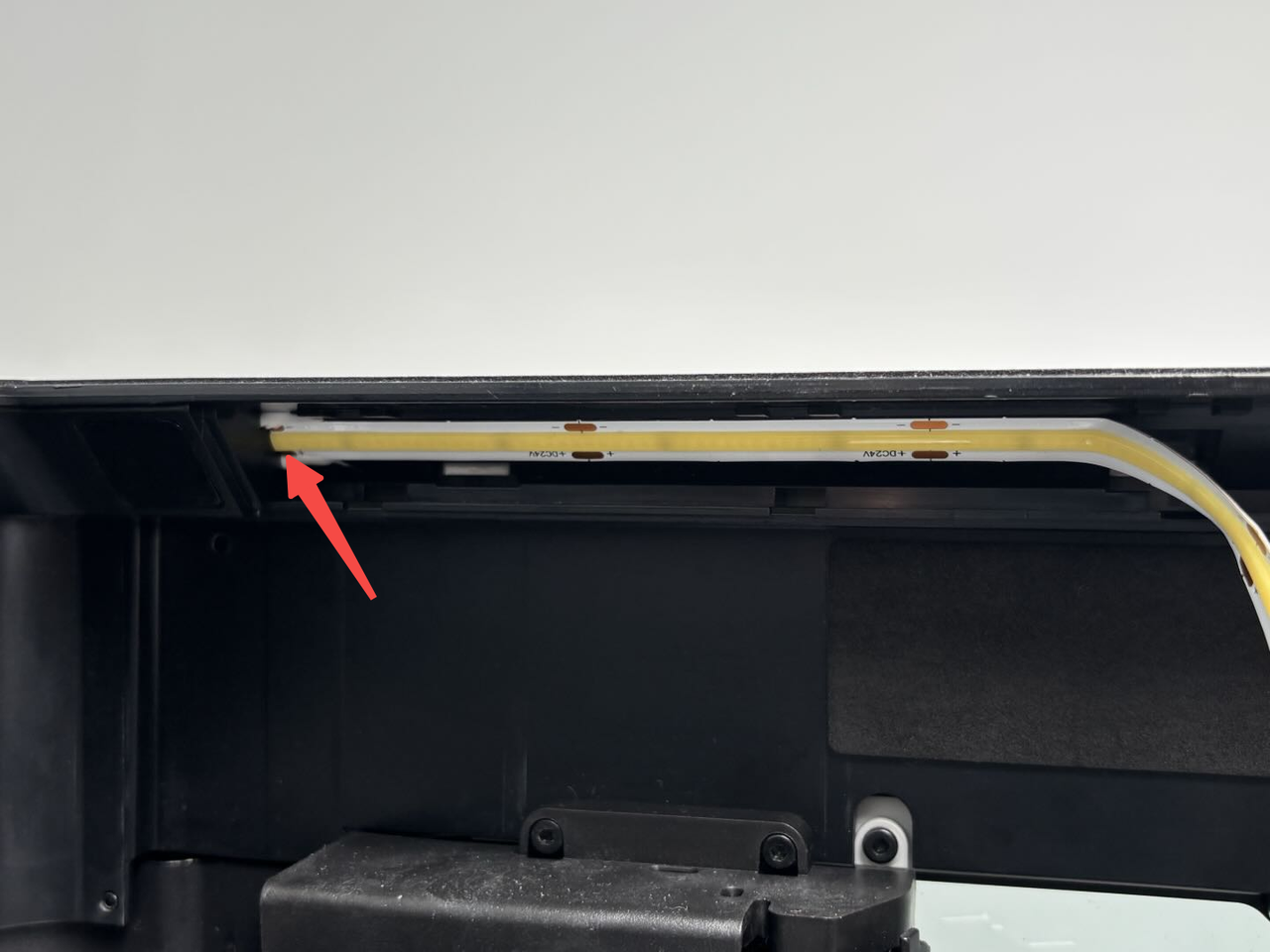
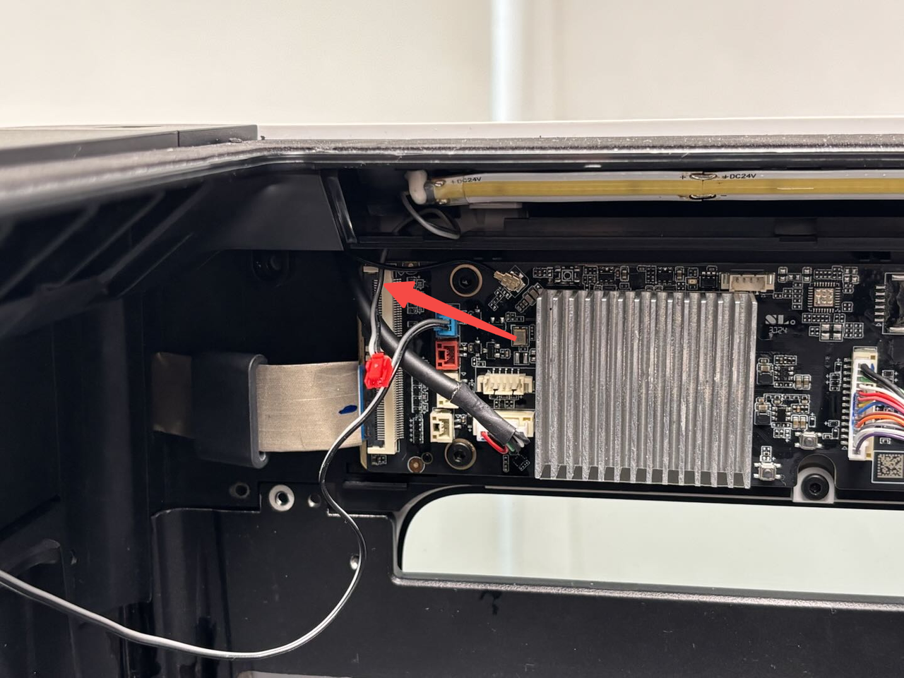
- Thread the LED cable through the small hole, then snap it into the cable channel and connect it to the AP board.

If your printer is H2D Laser Version, please follow this extra step:
Step 2: Install the birdseye camera
Refer to this Wiki for installing the birdseye camera:
¶ Step 2: Install the top chamber LED cover
Align the clips under the top chamber LED cover with the slots on the upper frame of the printer, then push it up until you hear a "click" sound.
The left and right LED covers are the same and are installed in the same way.
¶ Step 3: Install the AP board cover
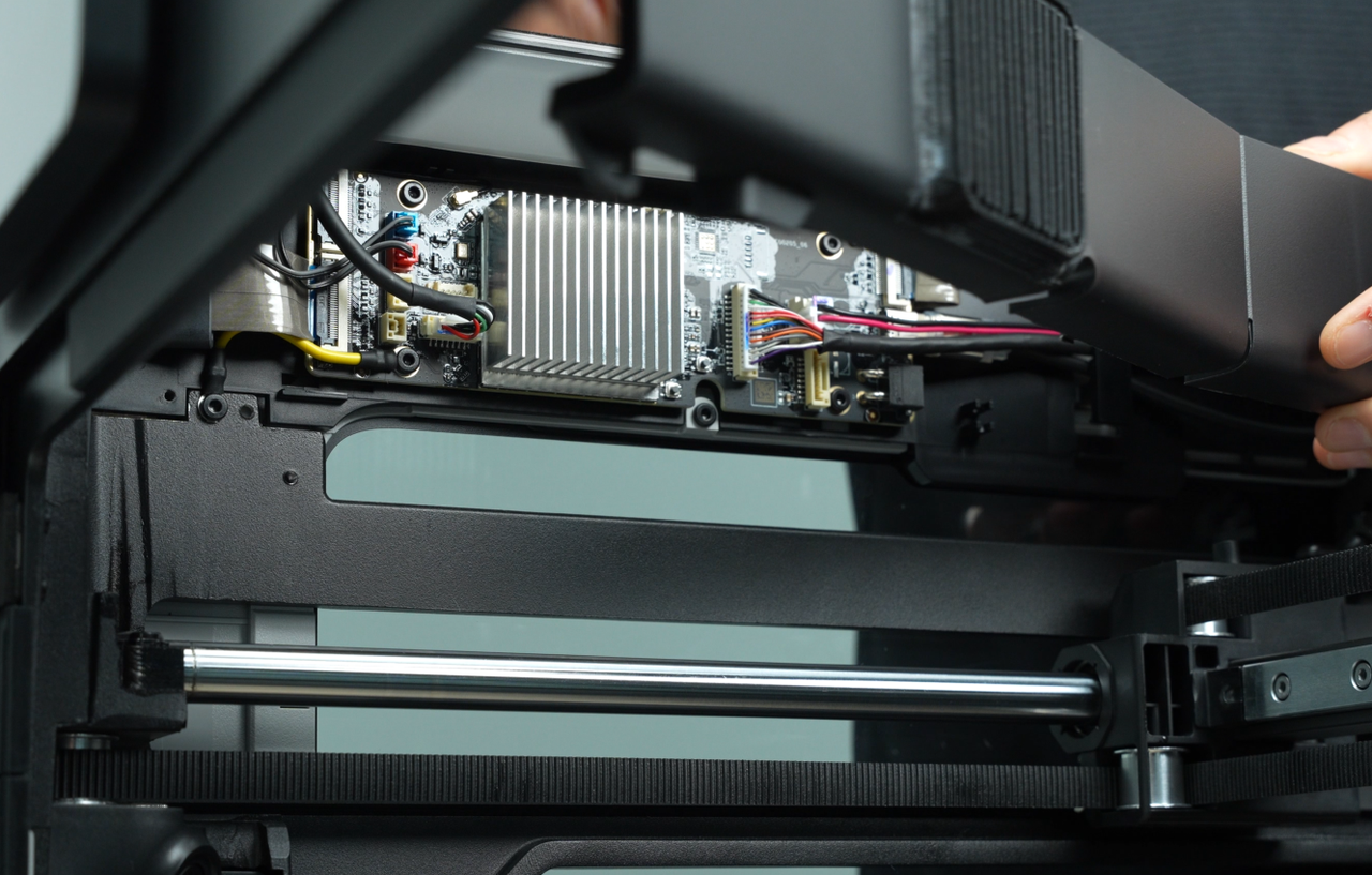
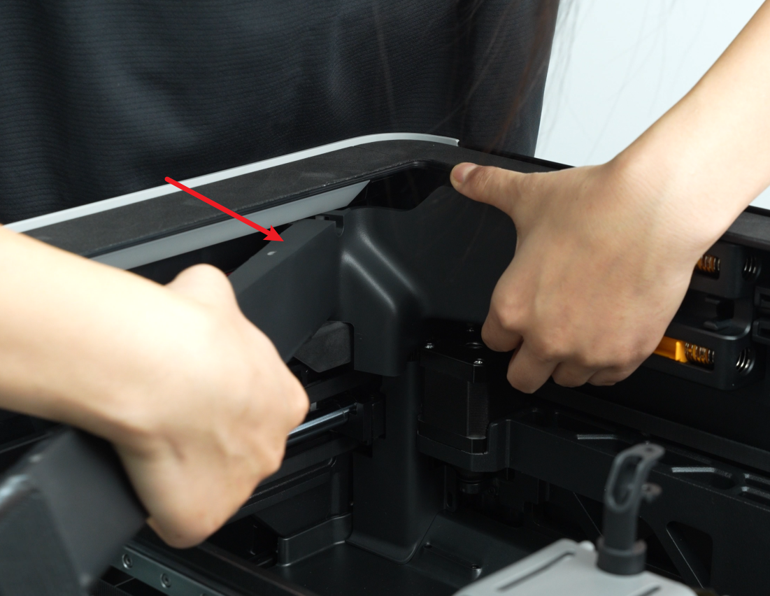
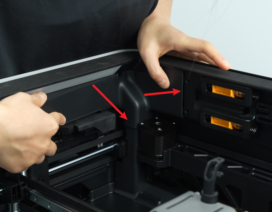
First, snap the AP board cover back from the side near the back of the printer, press the 2 spots indicated by the arrows into place, align the right side with the filament buffer, and align the bottom with the cable cover, then tighten one fixing screw (BT2.6x8) with an H2.0 Allen key.

¶ Replace the Left Top Chamber LED and Cover
¶ Remove the Left Top Chamber LED
¶ Step 1: Remove the top chamber LED cover
The top chamber LED cover is secured to the upper frame of the printer with clips. Use a flat pry tool or card to insert between the upper frame and the LED cover, then pry it off.
If you are only replacing the top chamber LED cover, you do not need to follow the subsequent steps.
¶ Step 2: Remove the AP board cover
Use an H2.0 Allen key to unscrew one fixing screw (BT2.6x8), then remove the AP board cover from the side near the front door.


¶ Step 3: Remove the top chamber LED
- Disconnect the top chamber LED cable from the AP board, and thread the cable through the small hole in the upper frame.

- Peel off the top chamber LED to remove it.
¶ Install the Left Top Chamber LED
¶ Step 1: Install the top chamber LED
- Peel off the backing of the new top chamber LED, align the end of the LED (the end without the connector) to the left side, and stick it back.
Just make sure it is tightly adhered.
- Thread the LED cable through the small hole, then connect it to the AP board.

¶ Step 2: Install the top chamber LED cover
Align the clips under the top chamber LED cover with the slots on the upper frame of the printer, then push it up until you hear a "click" sound.
The left and right LED covers are the same and are installed in the same way.


¶ Step 3: Install the AP board cover
First, snap the AP board cover back from the side near the back of the printer, press the 2 spots indicated by the arrows into place, align the right side with the filament buffer, and align the bottom with the cable cover, then tighten one fixing screw (BT2.6x8) with an H2.0 Allen key.

¶ Verify the Functionality
Connect the power cable and turn on the power. Control the top chamber LED using the screen, and check if it can be turned on and off normally. If it can be turned on and off normally, the replacement is successful.
Otherwise, check if the top chamber LED cable is connected correctly and try again. If the problem persists, contact Bambu Lab technical support for further assistance.
¶ End Notes
We hope the detailed guide provided has been helpful and informative.
If this guide does not solve your problem, please submit a technical ticket, we will answer your questions and provide assistance.
If you have any suggestions or feedback on this Wiki, please leave a message in the comment area. Thank you for your support and attention!