¶ USB Port Board
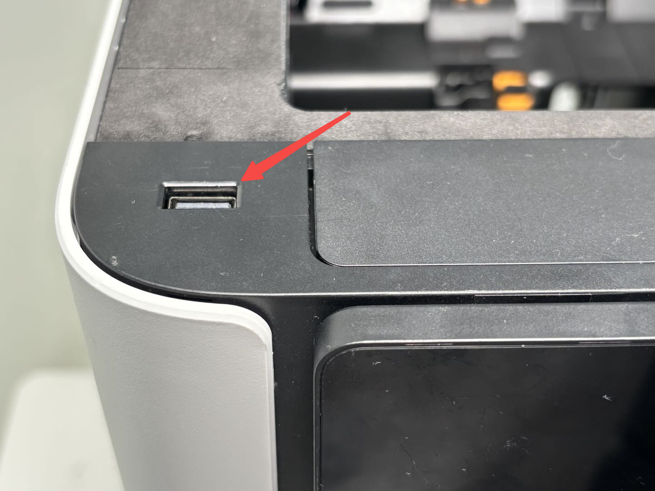
The USB port board is installed on the top of the printer.
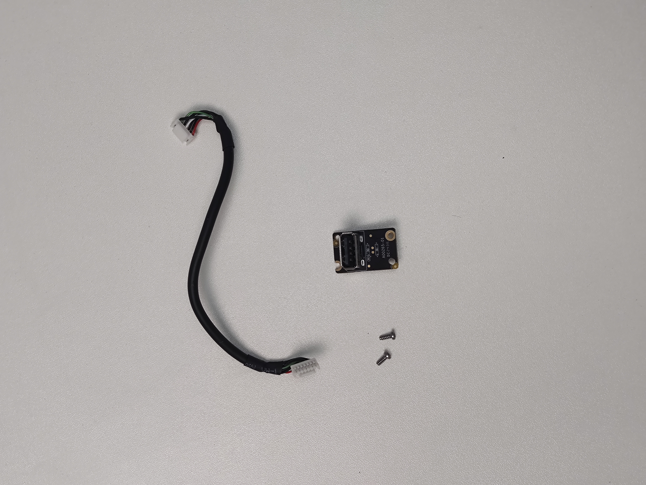
The spare parts of the USB port board include the following:
-
USB port board * 1
-
USB port board connector * 1 (no need to replace the cable if it is not damaged)
- BT2x5 screws - used to fix the USB port board * 2
¶ When to use
-
When the USB interface is damaged or abnormal, it needs to be replaced;
-
When the USB port board cable is damaged, it needs to be replaced.
¶ Tools and materials needed
-
New USB port board
-
H1.5 Allen key
Specifications and quantity of screws involved in replacing the H2D USB port board/USB port board connector (it is recommended to keep the removed screws properly to avoid loss):
Note: If only the USB port board is replaced, only the fixing screws of the front cover and USB port board need to be removed.
| Specification | Image | Use | Position | Quantity | |
|---|---|---|---|---|---|
| BT2×12 | Fix the front cover | 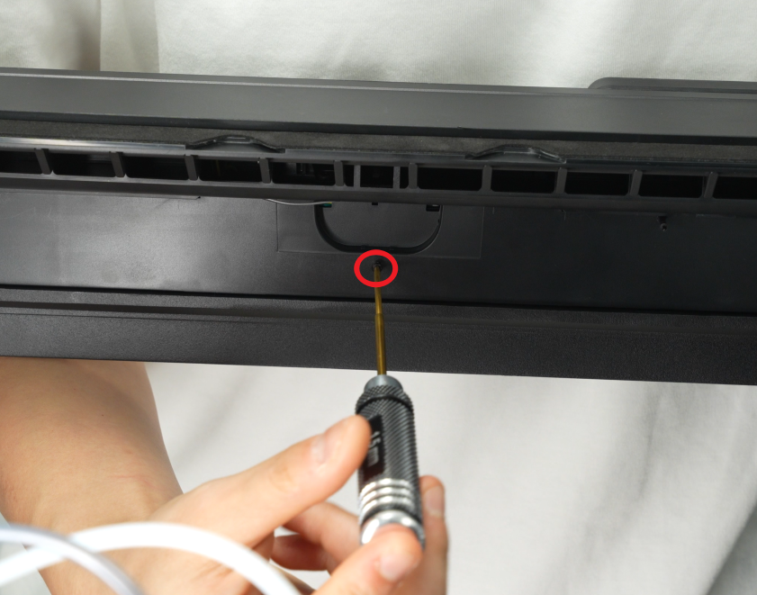 |
1 | ||
| BT2x5 | Fix the USB port board | 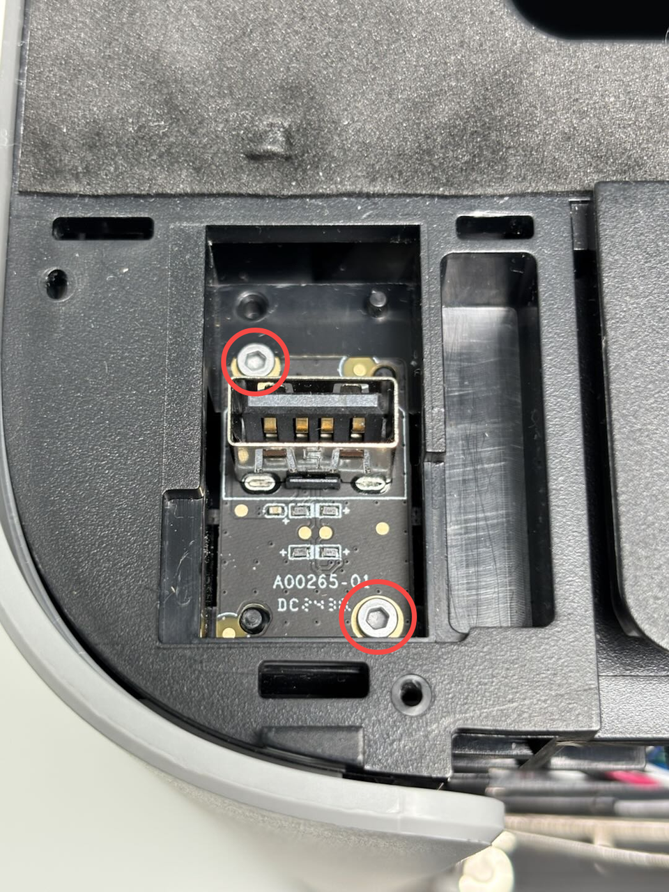 |
2 | ||
| BT2.6x8 | Fix the AP board cover |  |
1 | ||
| M3x3(nut diameter 10mm) | Fix the front glass door | 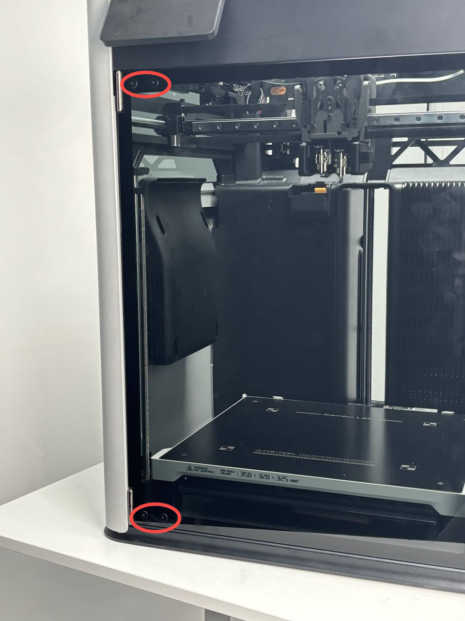 |
4 | ||
| BT3x16 | Fix the auxiliary part cooling fan | 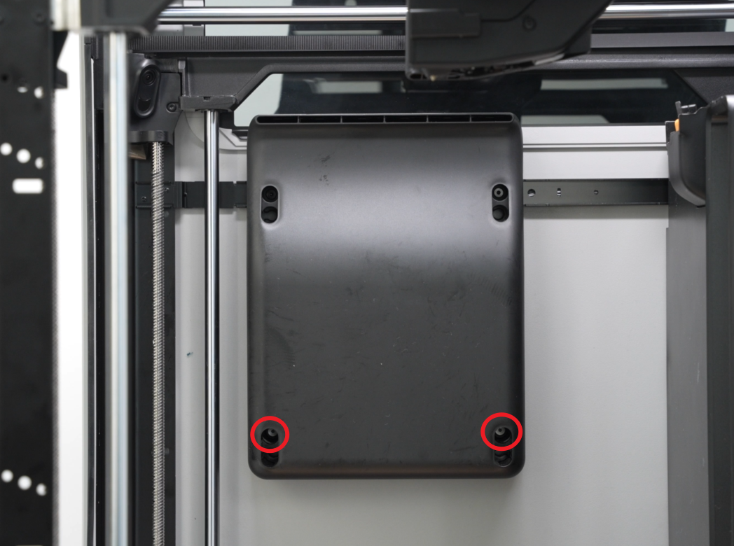 |
2 | ||
| BT3x8 | Fix the left side panel | 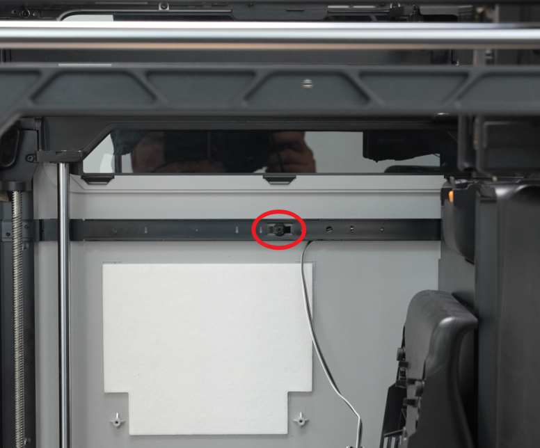 |
 |
3 | |
| Fix the rear panel (marked with green square) |  |
12 | |||
| ST3x6 | Fix the rear panel (marked with red circle) | 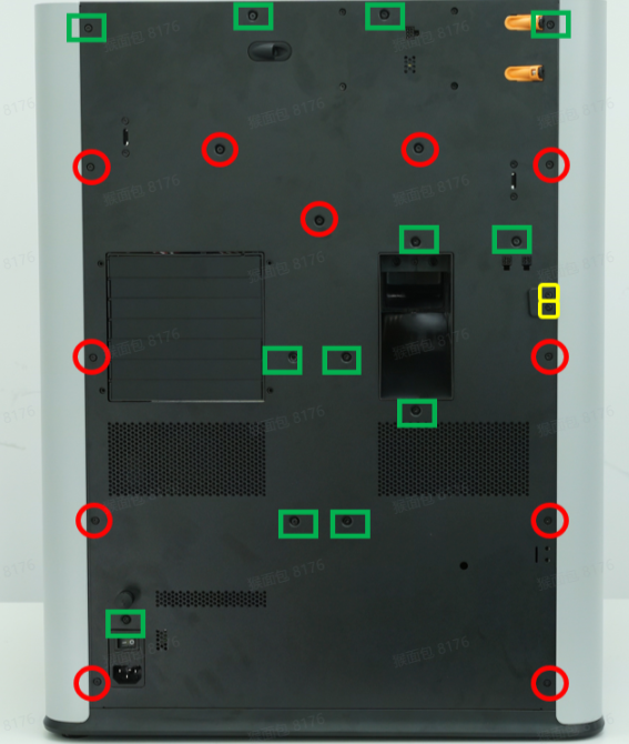 |
11 | ||
| ST3x12 | Fixed spool holder bracket (marked with yellow square) |  |
2 | ||
| ST3x3 | Fix the left side panel | 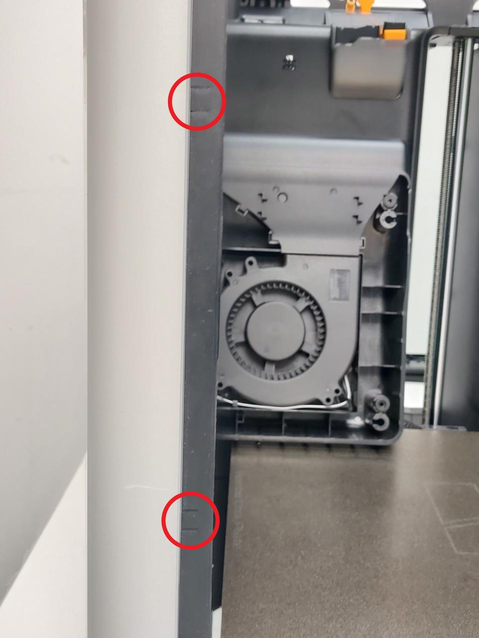 |
2 |
¶ Safety Warning
IMPORTANT!
It's crucial to power off the printer before conducting any maintenance work, including work on the printer's electronics and tool head wires. Performing tasks with the printer on can result in a short circuit, leading to electronic damage and safety hazards.
During maintenance or troubleshooting, you may need to disassemble parts, including the hotend. This exposes wires and electrical components that could short circuit if they contact each other, other metal, or electronic components while the printer is still on. This can result in damage to the printer's electronics and additional issues.
Therefore, it's crucial to turn off the printer and disconnect it from the power source before conducting any maintenance. This prevents short circuits or damage to the printer's electronics, ensuring safe and effective maintenance. For any concerns or questions about following this guide, we recommend submitting a technical ticket regarding your issue and we will do our best to respond promptly and provide the assistance you need.
¶ Replace the USB Port Board
¶ Remove the USB port board
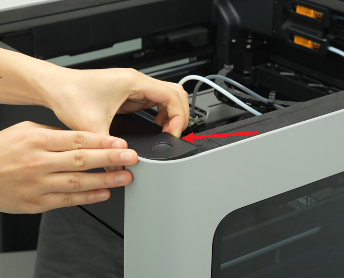
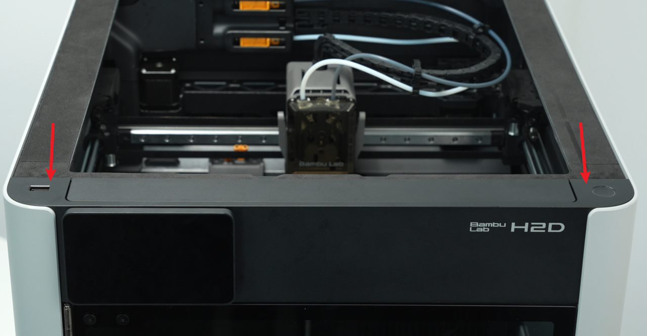
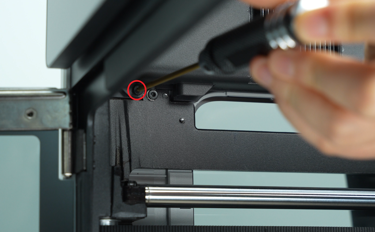
¶ Step 1: Remove the front cover
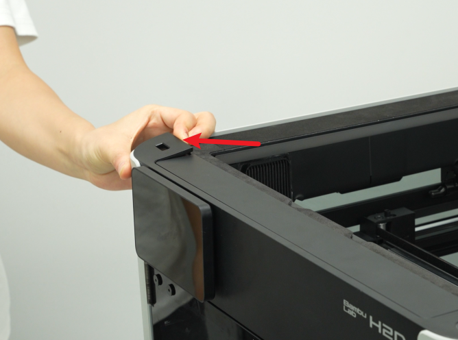
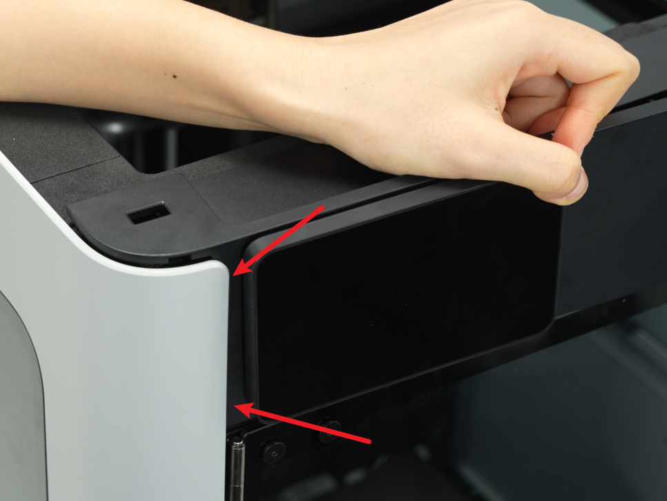
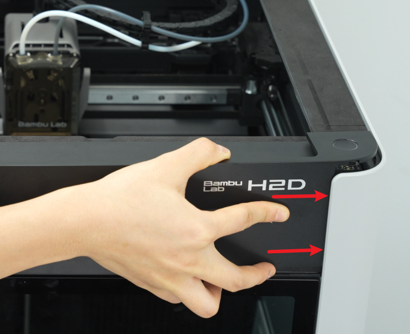
- Use an H1.5 Allen key to remove a fixing screw (BT2×12), then hold the buckle on the left side of the front cover with your hand, snap off the top left side of the front cover, and then snap open the top right side:

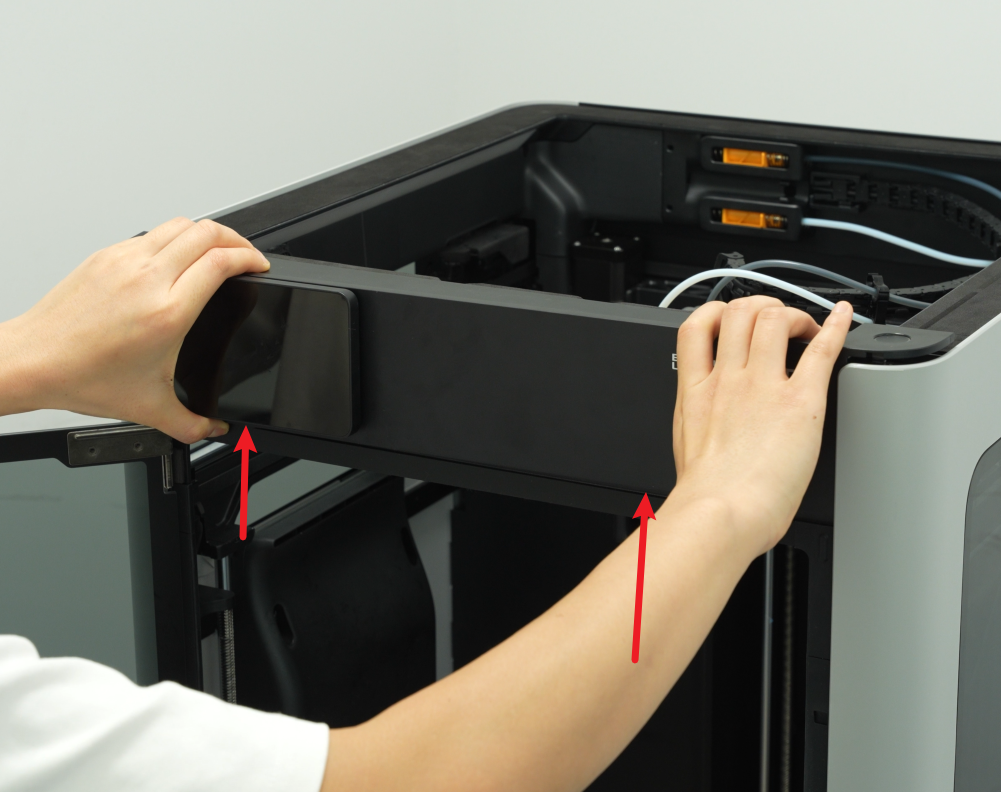
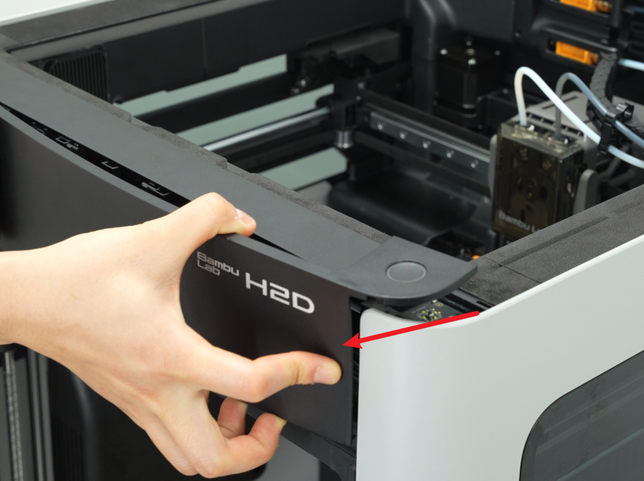
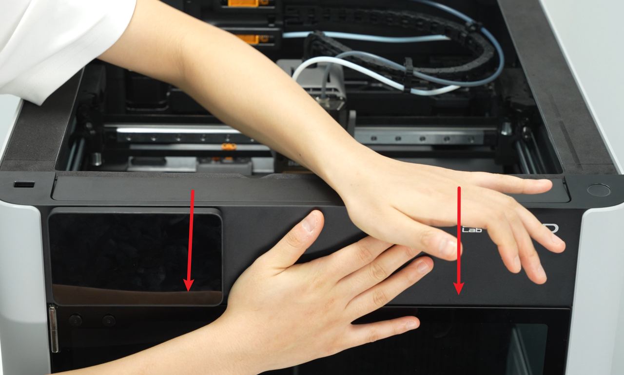
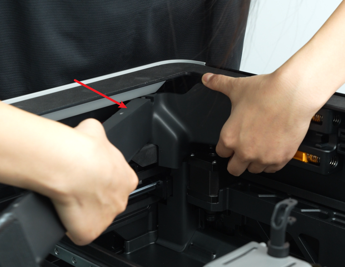
- Then place your thumbs on the bottom of the front cover and push upwards to unlock the front cover card. Then hold the right side of the front cover to bend it slightly and pull the right side of the front cover out from under the right side panel.
Please pull it out carefully to avoid damaging the screen FPC!
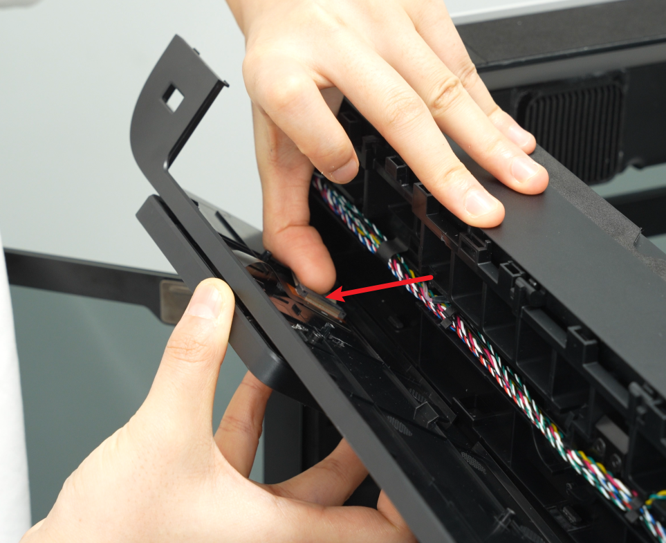
- After pulling the right side of the front cover out of the printer, carefully flip the front cover over to expose the interface between the screen and the screen FPC. Unfasten the buckle of the screen cable upwards, and then remove the screen cable from the buckle.
If you have any questions about the process of removing the front cover, you can refer to this Wiki: Replace H2D Front Cover
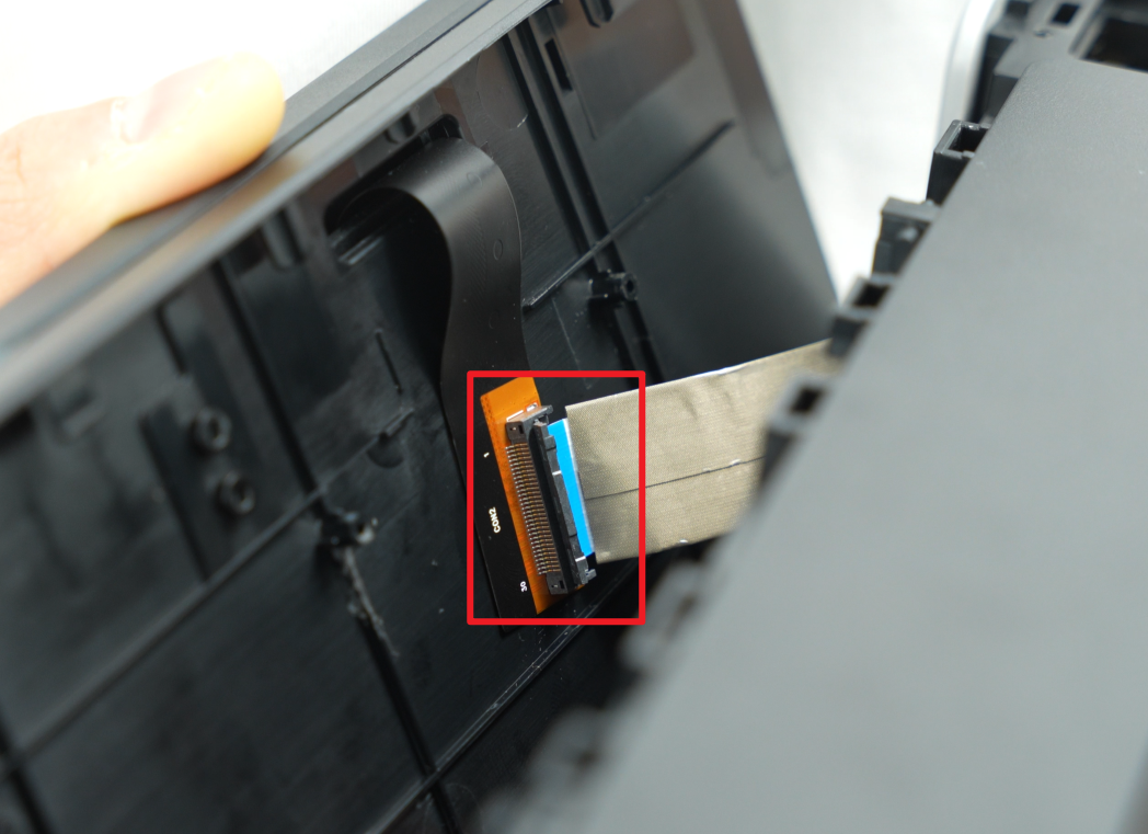
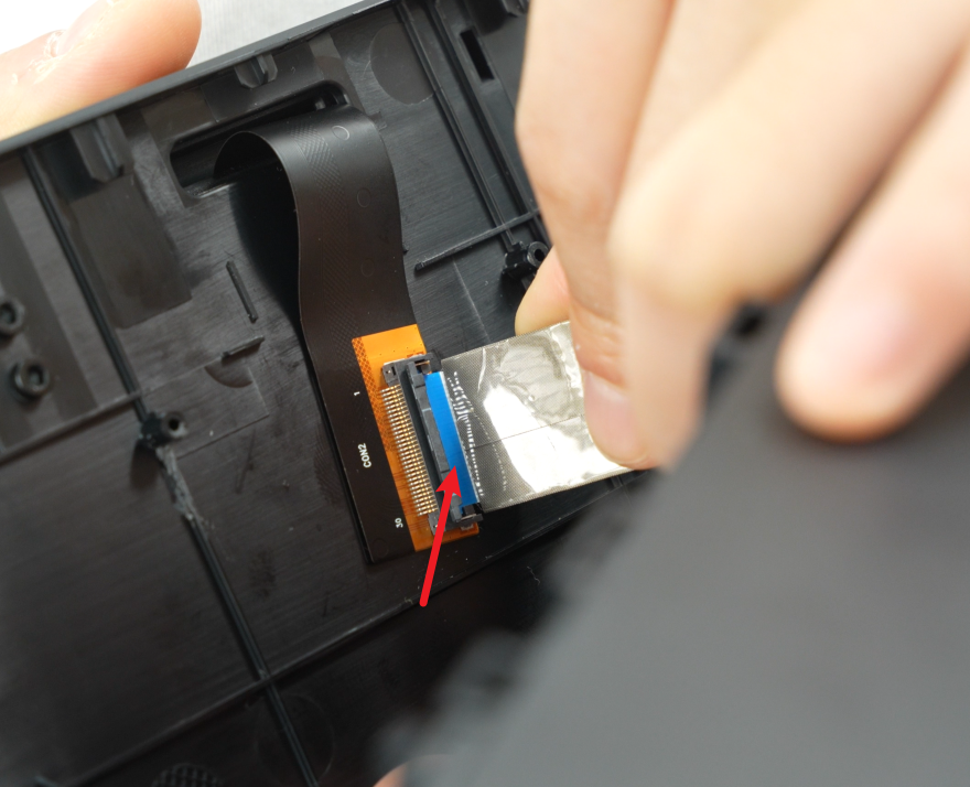
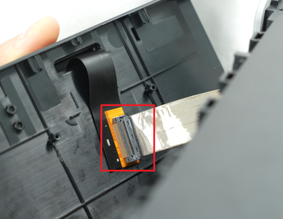
¶ Step 2: Remove the USB port board
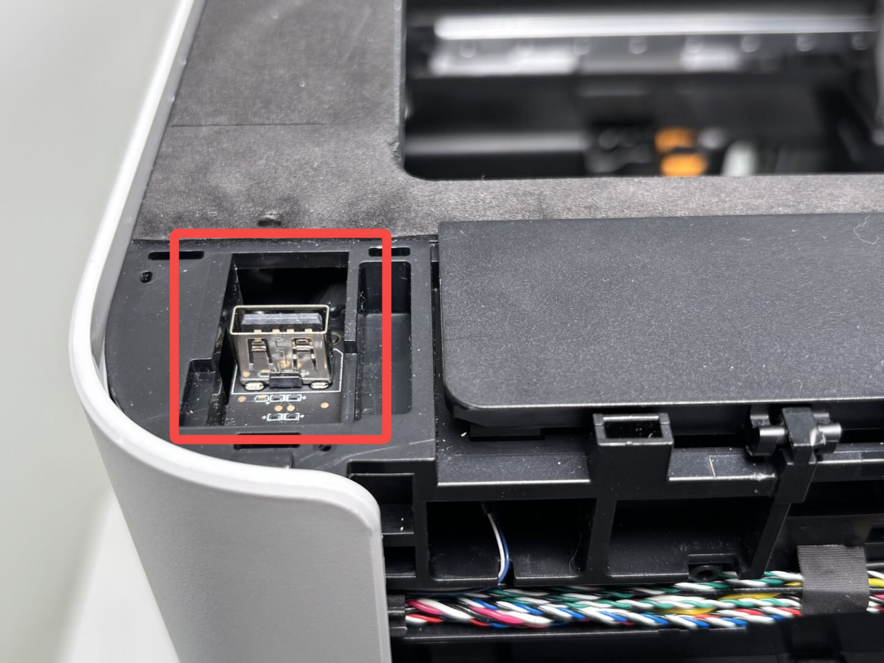
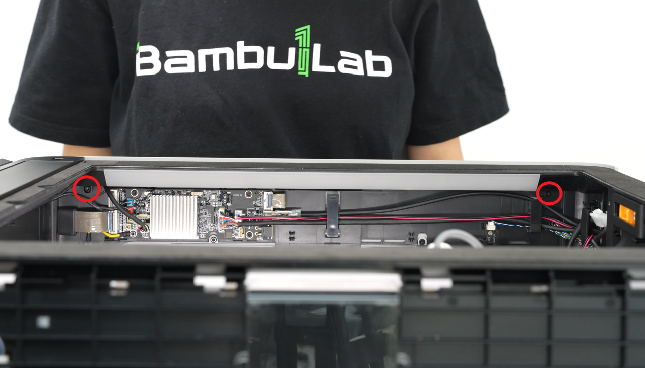
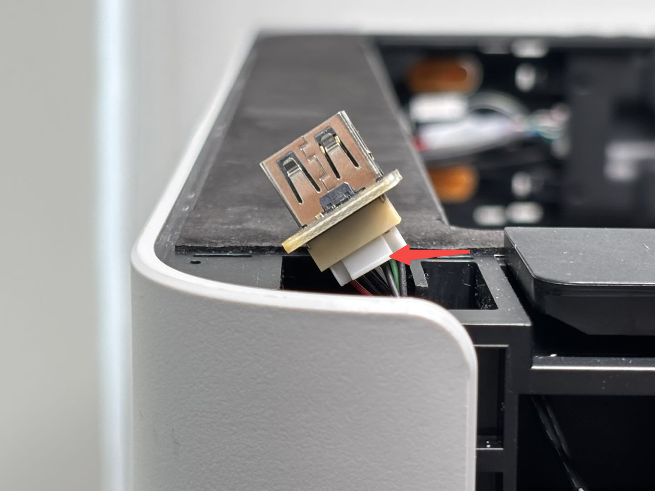
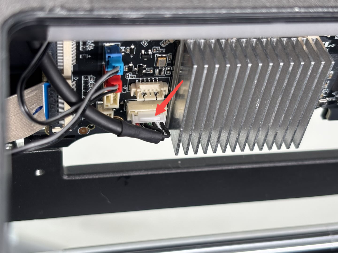
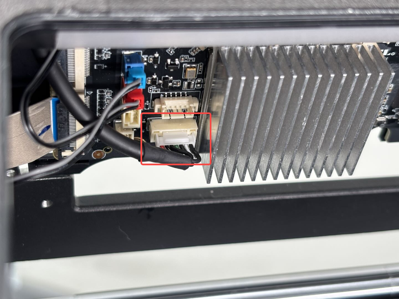
- Use an H1.5 Allen key to loosen the two fixing screws (BT2x5);

- Pull the USB port board slightly out of the upper frame, press the buckle on the connector (as indicated by the arrow), and disconnect the connector on the back of the USB port board.

¶ Install the USB port board
¶ Step 1: Install the USB port board
- Connect the new USB port board to the cable;

- Replace the USB port board and tighten the 2 fixing screws (BT2x5) using an H1.5 Allen key.

¶ Step 2: Install the front cover
- First, move the left side of the front cover closer to the left side of the printer, insert the screen FPC into the plug, and then fasten the black buckle;
- Then hold the right side of the front cover and bend it slightly, insert the right side of the front cover into the printer, and then press the front cover down to make sure all the buckles are in place.
- Finally, use a H1.5 Allen key to tighten a fixing screw (BT2x12).

¶ Replace the USB Port Board Connector
If the cable shows no visible damage, there is no need to replace it!
¶ Remove the USB port board connector
¶ Step 1: Remove the front cover
You can refer to this Wiki to remove the front cover. For the convenience of subsequent installation, you do not need to remove the screen from the front cover.
¶ Step 2: Remove the AP board cover
Use an H2.0 Allen key to remove 1 fixing screw (BT2.6x8), and then remove the AP board cover from the side near the front door.
¶ Step 3: Remove the left side panel
You can refer to this Wiki to remove the left side panel:Replace H2D Left/Right Side Panel
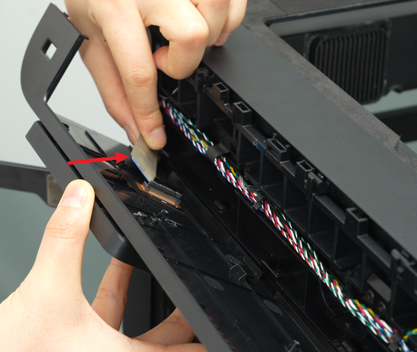
¶ Step 4: Remove the USB port board connector
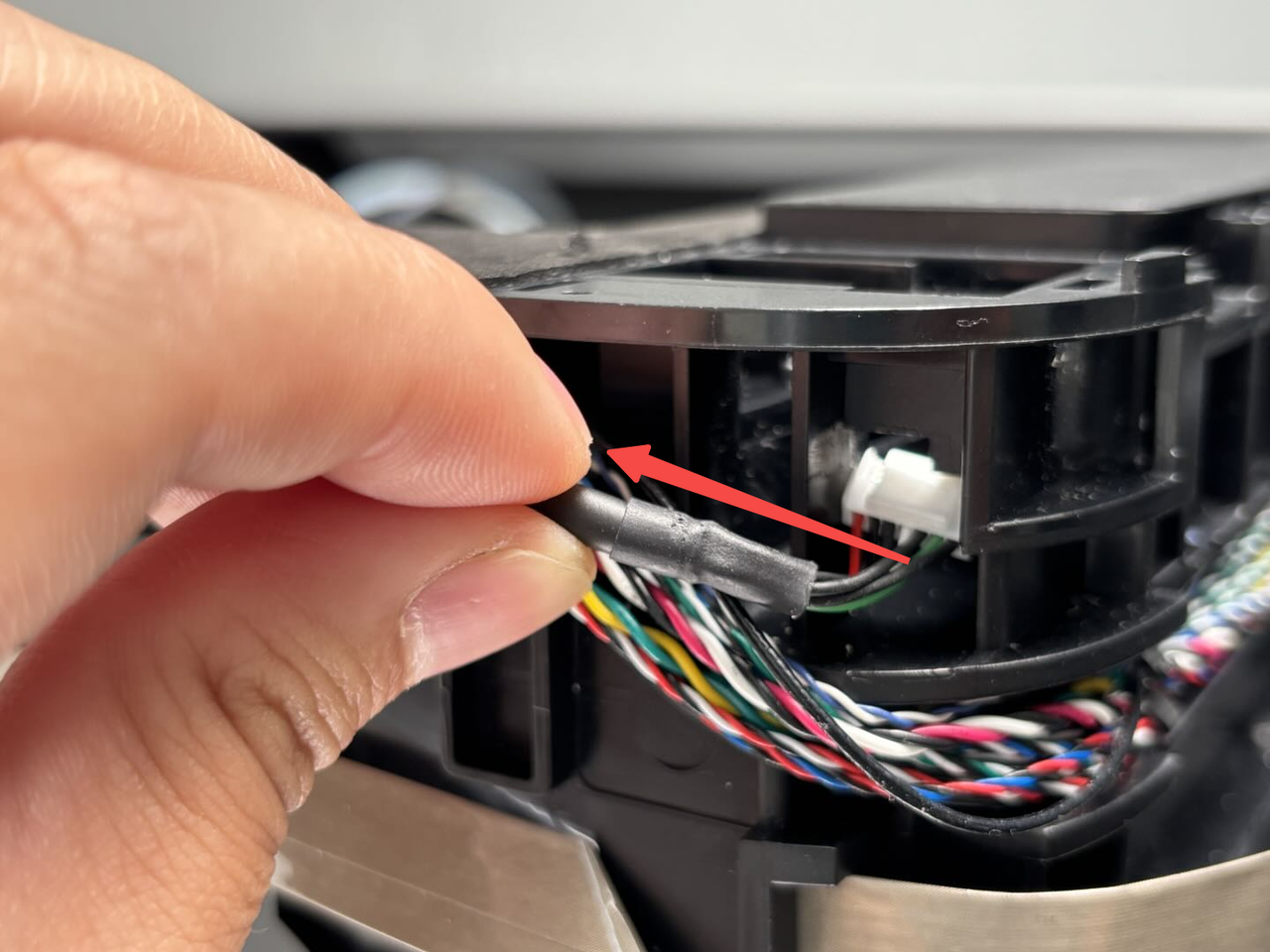
- Use an H1.5 Allen key to loosen the two fixing screws (BT2x5), then pull the USB port board out a little, press the buckle on the connector (as indicated by the arrow), and disconnect the USB port board from the cable;

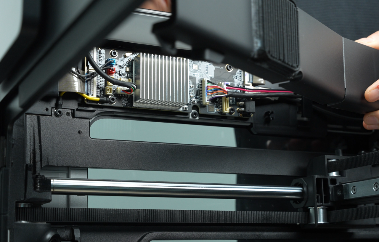
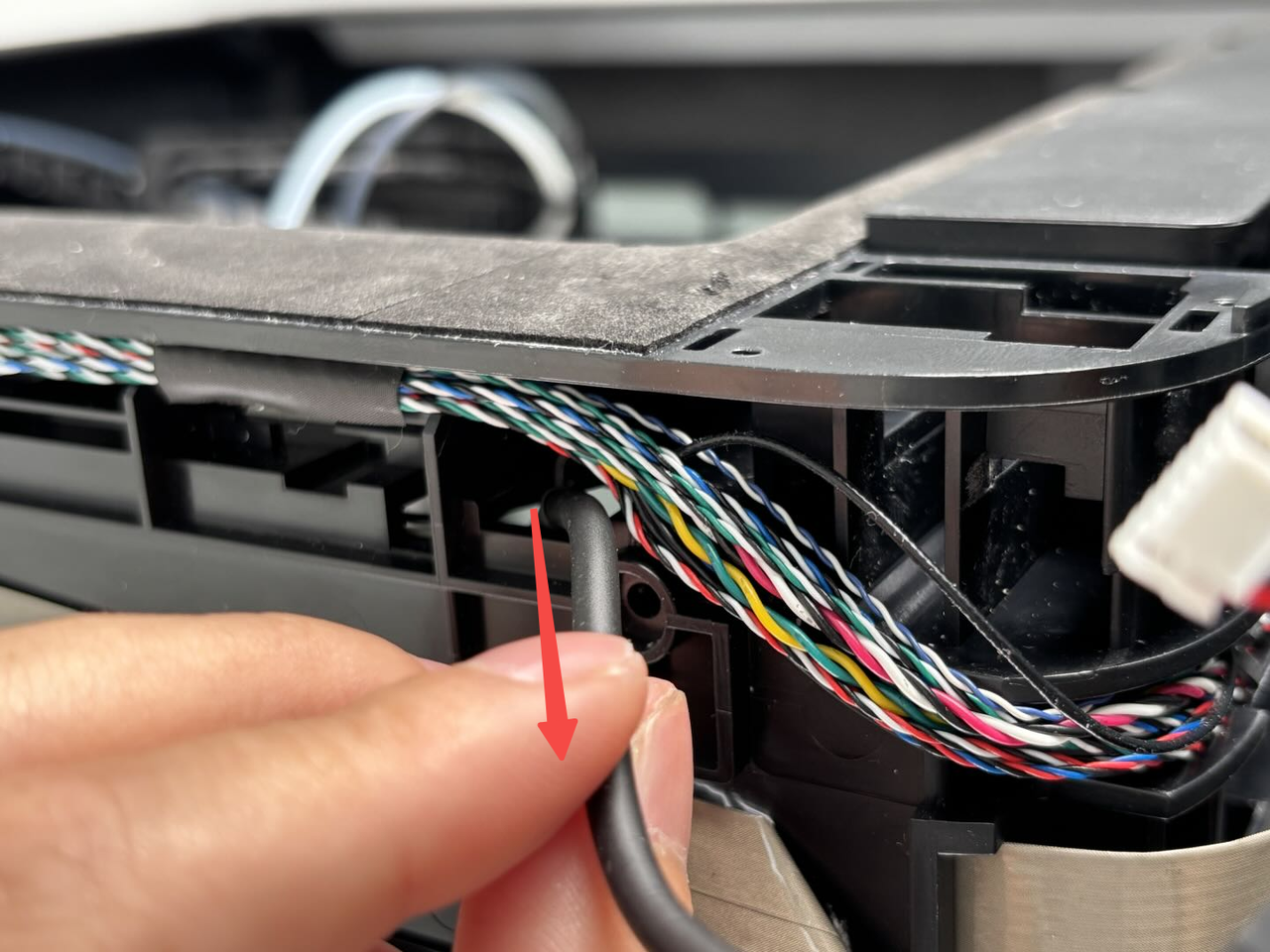
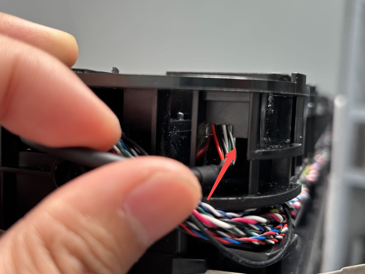
- Then press the buckle of the USB port board cable connector on one side of the AP board (as indicated by the arrow), separate the cable from the AP board, and then pull the connector out of the upper frame.
¶ Install the USB port board connector
¶ Step 1: Install the USB port board connector
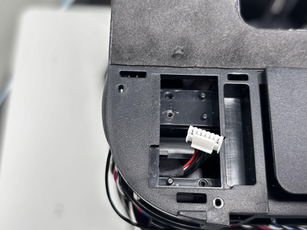
- Pass one end of the USB port board connector through the small hole in the upper frame and connect it to the AP board;
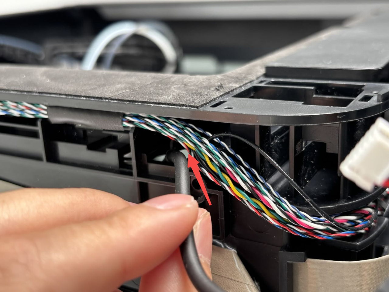
- Pass the other cables through the small holes on the outermost side of the upper frame, and then connect the cables to the USB port board. Align the USB port board with the screw holes and tighten the two fixing screws with an H1.5 Allen key.


¶ Step 2: Install the left side panel
You can refer to this Wiki to install the left side panel:Replace H2D Left/Right Side Panel
¶ Step 3: Install the AP board cover
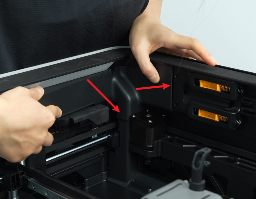
First, snap the AP board cover back from the side close to the back of the printer, press both arrows into place, flush with the right side of the filament buffer and the bottom with the cable cover, and then tighten a fixing screw (BT2.6x8) using an H2.0 Allen key.

¶ Step 4: Install the front cover
You can refer to this Wiki to install the front cover.
¶ Verify the Functionality
Turn on the printer power, insert the USB flash drive into the USB port, and check whether the printer can detect the USB flash drive normally.
¶ End Notes
We hope the detailed guide provided has been helpful and informative.
If this guide does not solve your problem, please submit a technical ticket , we will answer your questions and provide assistance.
If you have any suggestions or feedback on this Wiki, please leave a message in the comment area. Thank you for your support and attention!