¶ WiFI Antenna
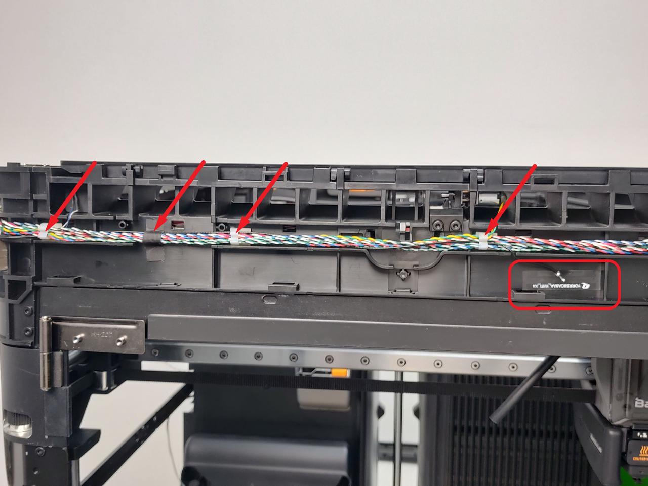
The WiFi antenna is installed in the upper frame and serves as an electronic component to enhance wireless network signals.
The WiFI Antenna spare parts include:
Wifi Antenna
¶ When to Use
-
The WiFi antenna is damaged.
-
The WiFi signal is unstable or weak.
¶ Tools and materials needed
-
New WiFi Antenna
-
H2.0 Allen Key
Specifications and quantity of screws involved in replacing the H2D WiFi antenna (it is recommended to keep the removed screws properly to avoid loss):
| Specification | Image | Use | Position | Quantity | |
|---|---|---|---|---|---|
| BT2×12 | Fix the front cover | 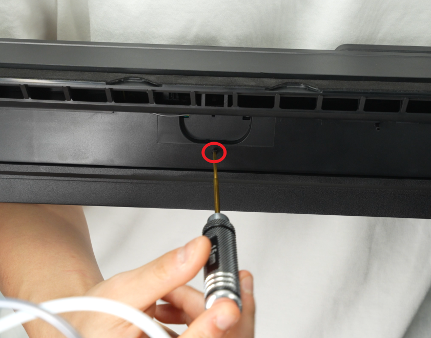 |
1 | ||
| BT2.6x8 | Fix the AP board cover |  |
1 | ||
| M3x3(nut diameter 10mm) | Fix the front glass door | 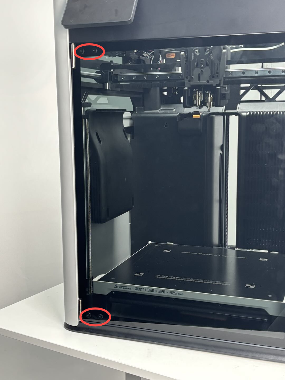 |
4 | ||
| BT3x16 | Fix the auxiliary part cooling fan | 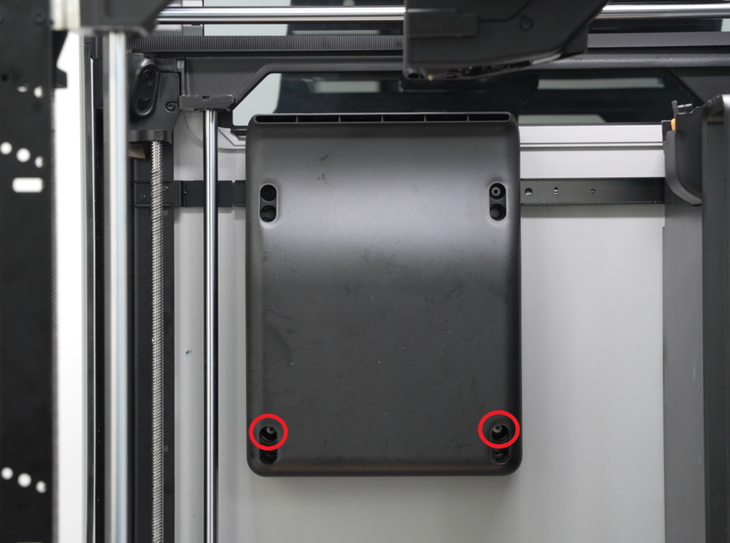 |
2 | ||
| BT3x8 | Fix the left side panel | 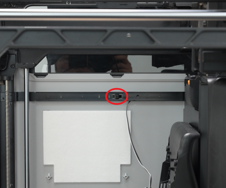 |
 |
3 | |
| Fix the rear panel (marked with green square) | 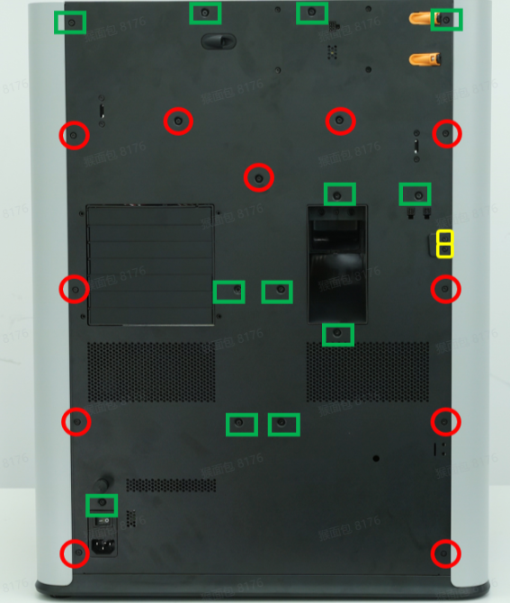 |
12 | |||
| ST3x6 | Fix the rear panel (marked with red circle) |  |
11 | ||
| ST3x12 | Fixed spool holder bracket (marked with yellow square) |  |
2 | ||
| ST3x3 | Fix the left side panel | 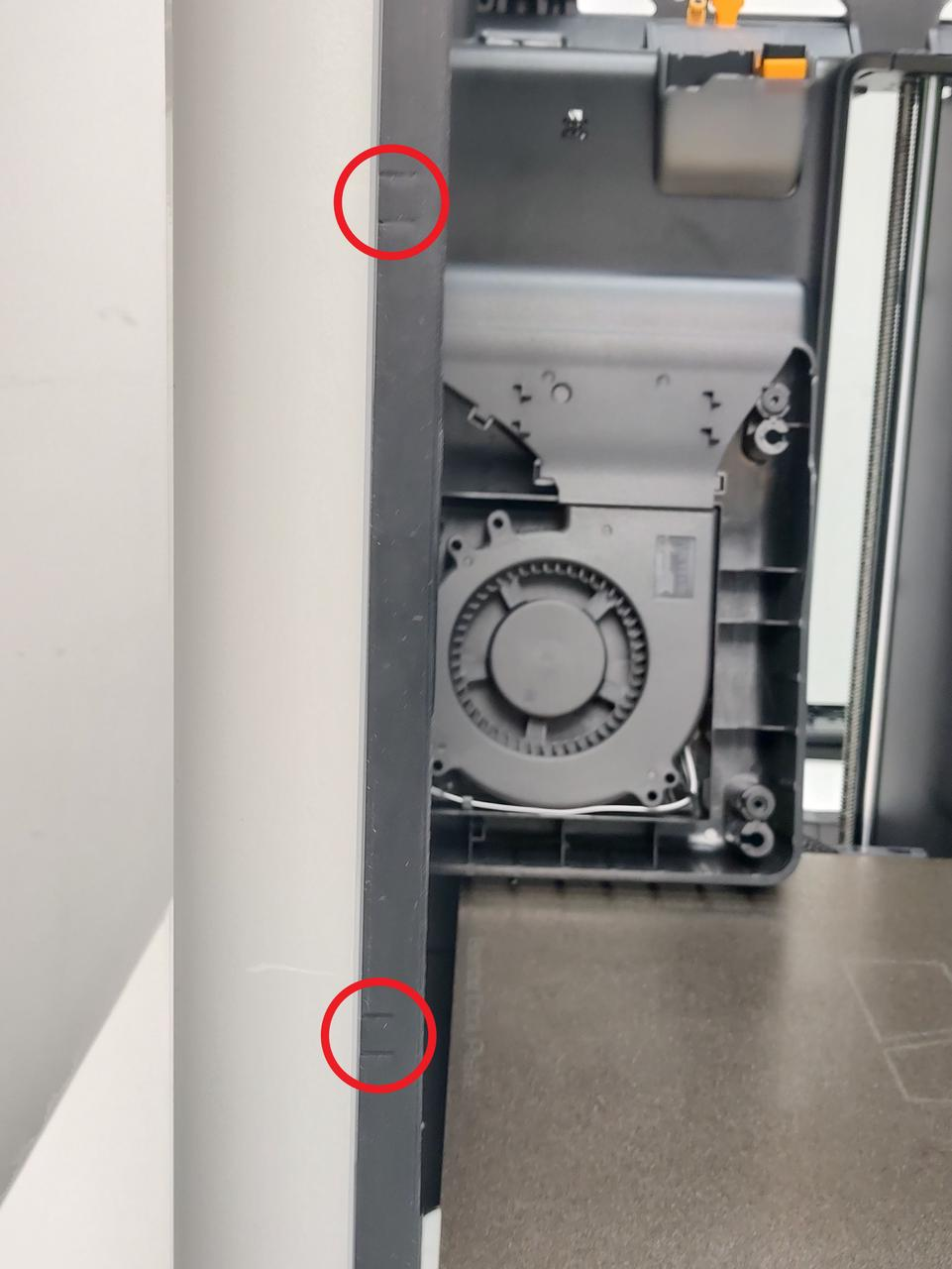 |
2 |
¶ Safety Warning
IMPORTANT!
It's crucial to power off the printer before conducting any maintenance work, including work on the printer's electronics and tool head wires. Performing tasks with the printer on can result in a short circuit, leading to electronic damage and safety hazards.
During maintenance or troubleshooting, you may need to disassemble parts, including the hotend. This exposes wires and electrical components that could short circuit if they contact each other, other metal, or electronic components while the printer is still on. This can result in damage to the printer's electronics and additional issues.
Therefore, it's crucial to turn off the printer and disconnect it from the power source before conducting any maintenance. This prevents short circuits or damage to the printer's electronics, ensuring safe and effective maintenance. For any concerns or questions about following this guide, we recommend submitting a technical ticket regarding your issue and we will do our best to respond promptly and provide the assistance you need.
¶ Remove the WiFi Antenna
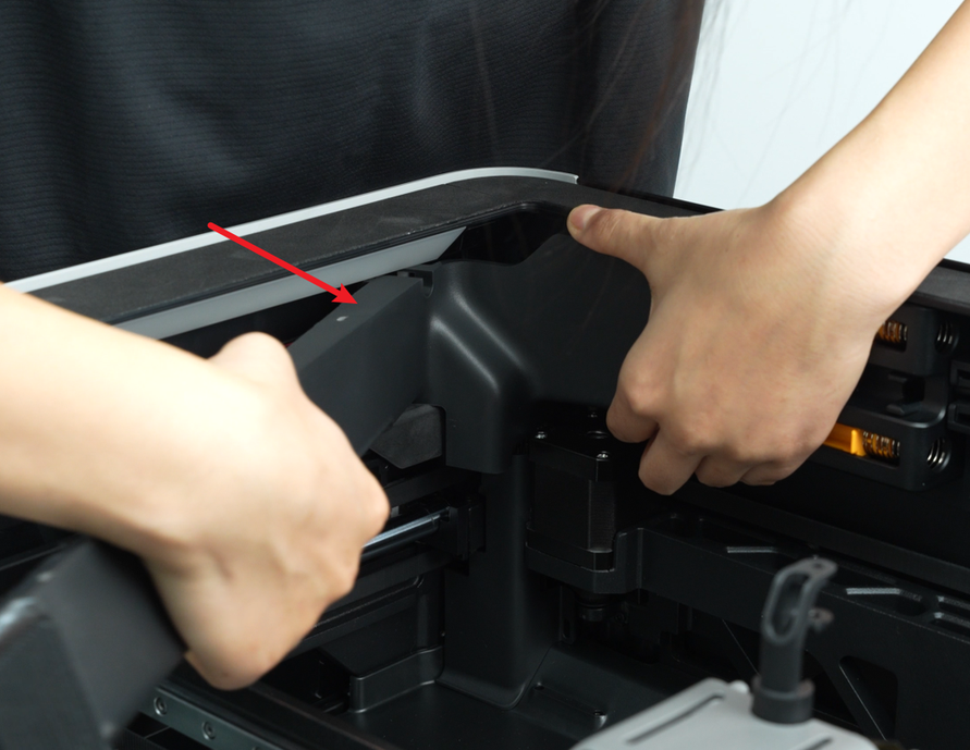
¶ Step 1: Remove the front cover
You can refer to this Wiki to remove the front cover. For the convenience of subsequent installation, you do not need to remove the screen from the front cover.
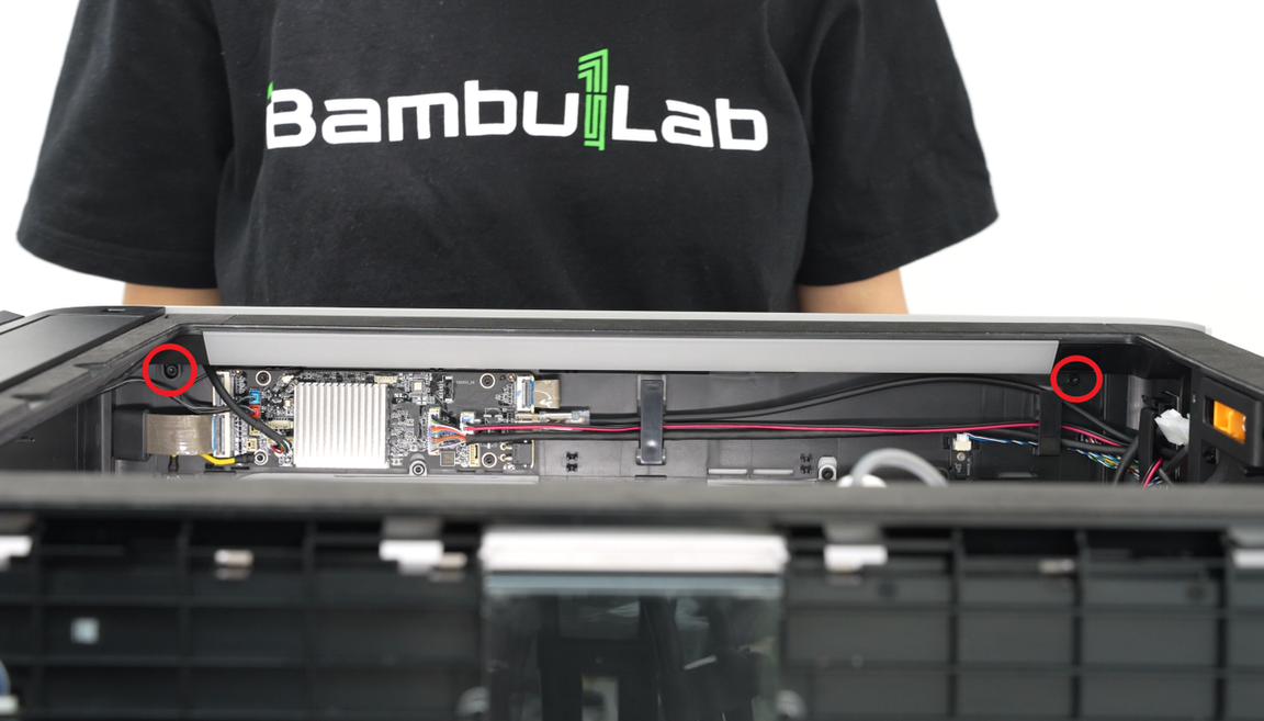
¶ Step 2:Remove the AP board cover
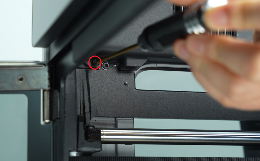
Use an H2.0 Allen key to remove 1 fixing screw (BT2.6x8), and then remove the AP board cover from the side near the front door.

¶ Step 3: Remove the left side panel
You can refer to this Wiki to remove the left side panel: Replace the H2D Left/Right Side Panel
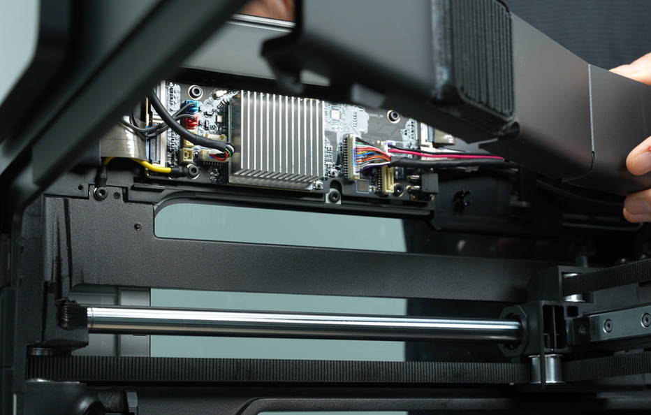
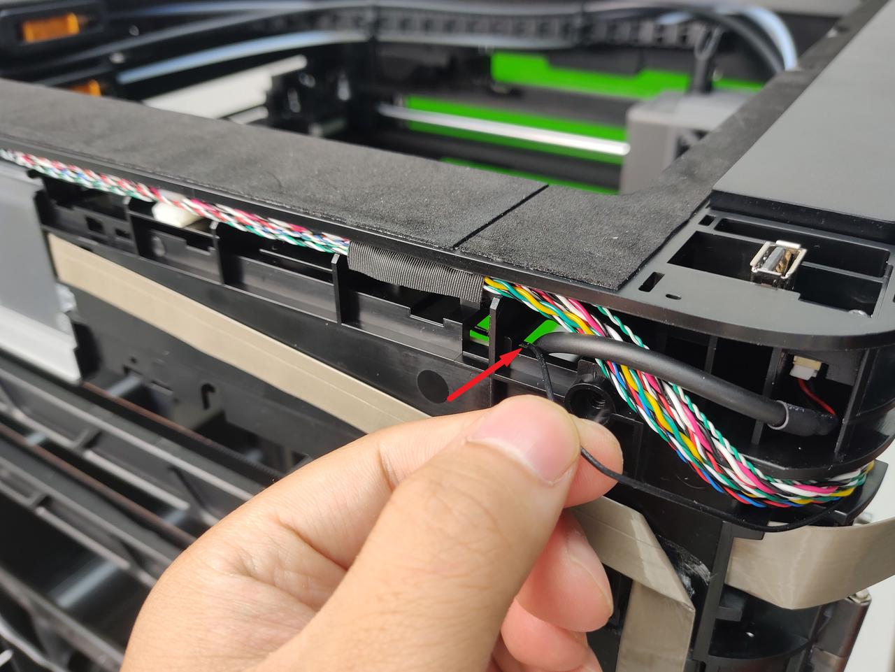
¶ Step 4: Remove the Wifi antenna
- Disconnect the WiFi antenna from the AP board and pull it out from the small hole in the upper frame;

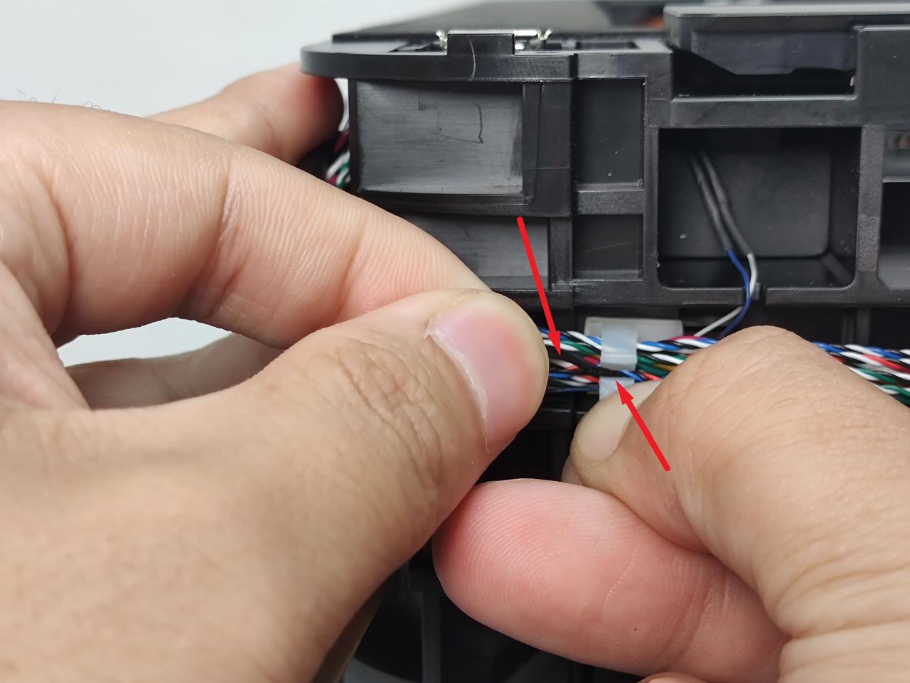
- Then remove the WiFi antenna from the cable clip and the tape in turn. You need to press one side of the white cable clip, then take out the WiFi antenna, remove it from the gap of the cable clip, and tear the WiFi antenna off the front cover to remove it.
¶ Install the WiFi Antenna
¶ Step 1: Reinstall the WiFi Antenna
- Remove the adhesive backing of the new WiFi antenna, then stick the WiFi antenna back to its original position, and buckle the WiFi antenna into the cable clips one by one.

- Pass the WiFi antenna through the small wiring hole on the upper frame and connect it to the AP board.


¶ Step 2: Install the left side panel
You can refer to this Wiki to install the left side panel:
Replace the H2D Left/Right Side Panel
¶ Step 3: Install the AP board cover
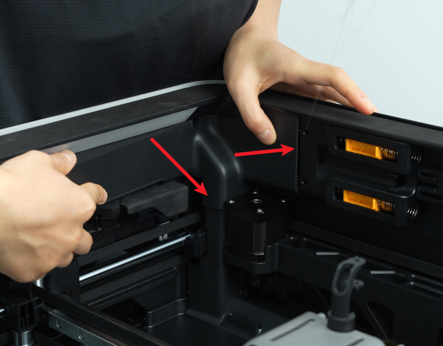
First, snap the AP board cover back from the side close to the back of the printer, press both arrows into place, flush with the right side of the filament buffer and the bottom with the cable cover, and then tighten a fixing screw (BT2.6x8) using an H2.0 Allen key.
¶ Step 4:Install the front cover
You can refer to this Wiki to install the front cover.
¶ Verify the Functionality
Turn on the printer, connect the printer to the network, and click Speed Test to confirm whether the function is normal.
¶ End Notes
We hope the detailed guide provided has been helpful and informative.
If this guide does not solve your problem, please submit a technical ticket, we will answer your questions and provide assistance.
If you have any suggestions or feedback on this Wiki, please leave a message in the comment area. Thank you for your support and attention!