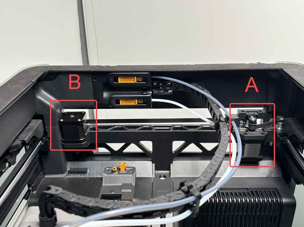
¶ X/Y Motors
The X/Y motors are installed on the back of the printer. They are stepper motors that drive the toolhead to move along the X and Y axes. There is one motor on each side (left and right). For easy identification, they are referred to as Motor A and Motor B based on their positions.
¶ When to Replace
-
The motor is stuck
-
Confirmed by Bambu Lab technical support that the motor needs to be replaced.
¶ Tools and Materials Needed
- New X/Y Motor
The X/Y motor kit includes:
-
1 x Motor
-
4 x MK3x6 Screws (for securing the motor)
-
2 x M3x6 Screws (for securing the motor bearing bracket)

- H2.0 Hex Key
You will need an extra-long H2.0 hex key (length must exceed 122 mm).

Screw Specifications and Quantities for Disassembly/Assembly
-
12 x BT3×8 Screw (for securing the back panel)
-
11 x ST3×6 Screw (for securing the back panel)
-
2 x ST3×12 Screw (for securing the filament spool holder base)
¶ Safety Warning
It's crucial to power off the printer before conducting any maintenance work, including work on the printer's electronics and tool head wires. Performing tasks with the printer on can result in a short circuit, leading to electronic damage and safety hazards.
During maintenance or troubleshooting, you may need to disassemble parts, including the hotend. This exposes wires and electrical components that could short circuit if they contact each other, other metal, or electronic components while the printer is still on. This can result in damage to the printer's electronics and additional issues.
Therefore, it's crucial to turn off the printer and disconnect it from the power source before conducting any maintenance. This prevents short circuits or damage to the printer's electronics, ensuring safe and effective maintenance. For any concerns or questions about following this guide, open a new ticket in our Support Page and we will do our best to respond promptly and provide the assistance you need.
¶ Replacing X/Y Motor (Motor A)
¶ Removing X/Y Motor (Motor A)
¶ Step 1: Remove the Rear Panel and Purge Chute
Refer to this Wiki guide for instructions on removing the printer's rear panel and purge chute:
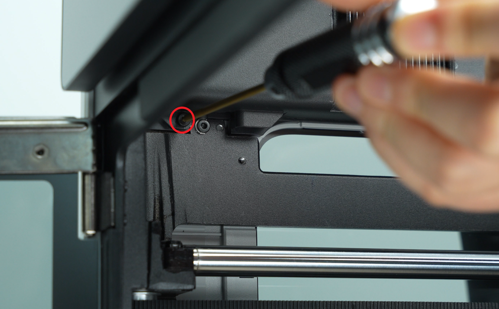
¶ Step 2: Remove the X/Y Belt Tensioner
- Use an H2.0 Hex Key to remove the two tension plate screws (M3×6) and the two tensioner bracket screws (M3×6).。
 |
 |
- Firmly push the X/Y belt tensioner out of its slot.
Some force is required for this step.

¶ Step 3: Remove X/Y Motor (A)
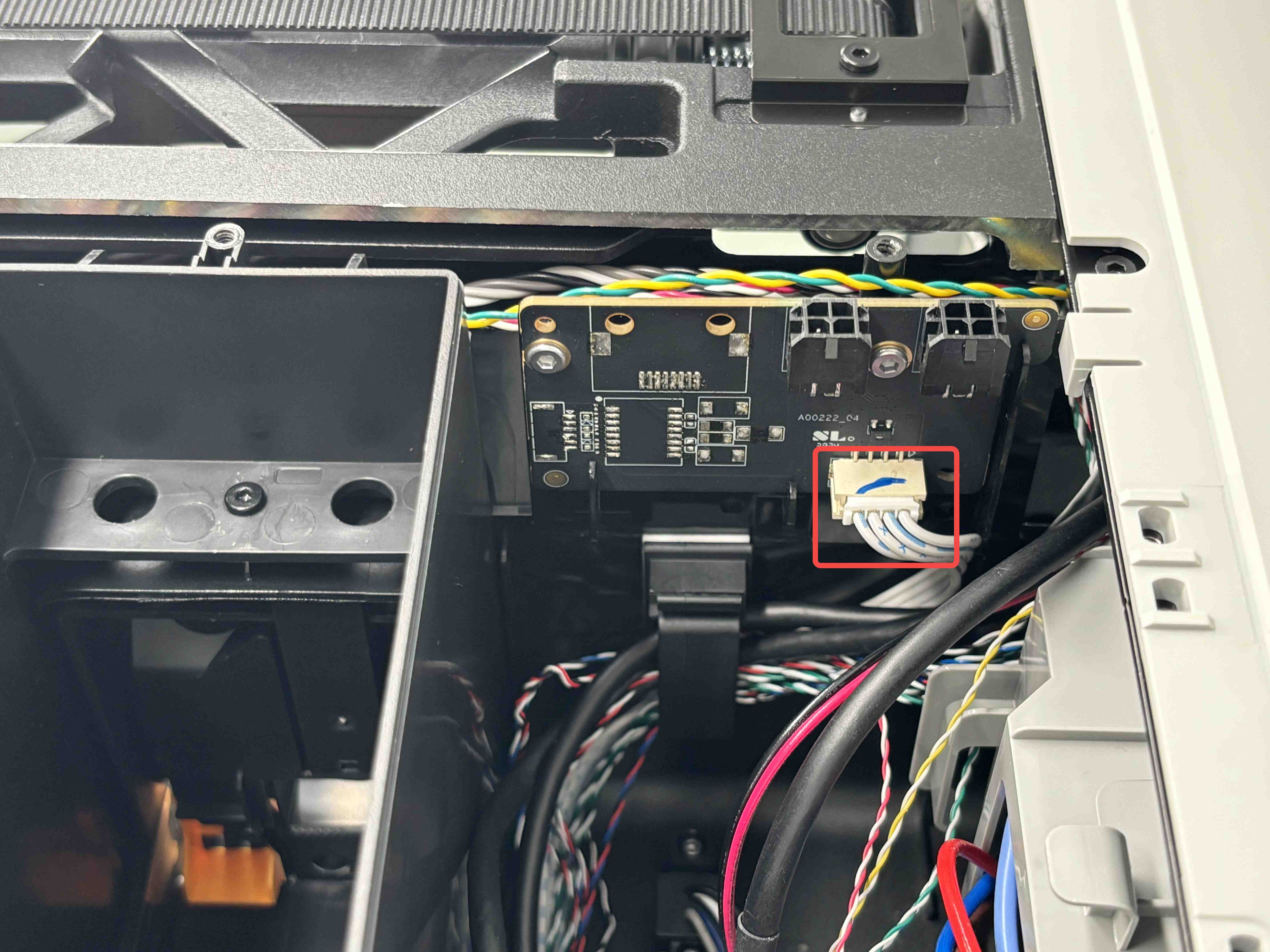
- Disconnect the motor cable connector from the MC board.
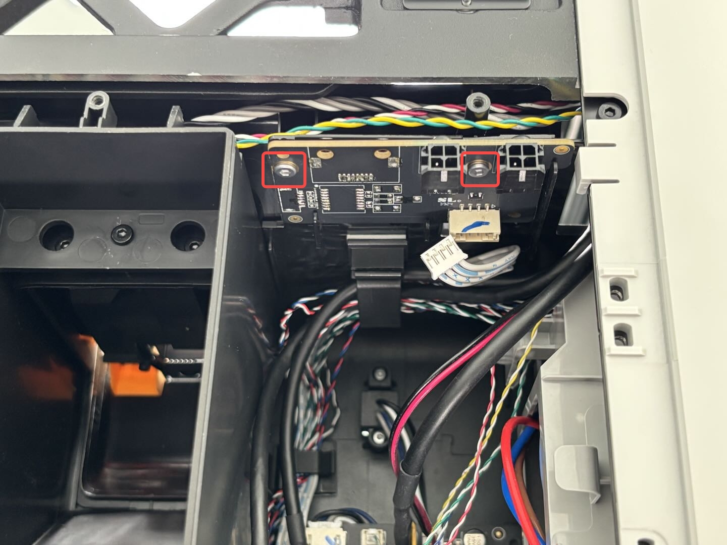
The MC board heatsink might block access—if so, remove the two heatsink screws and take the heatsink off temporarily. Then disconnect the motor cable and pull it out of the cable routing channel.
 |
 |
The blue material under the heatsink is thermal paste. Do not wipe it off.
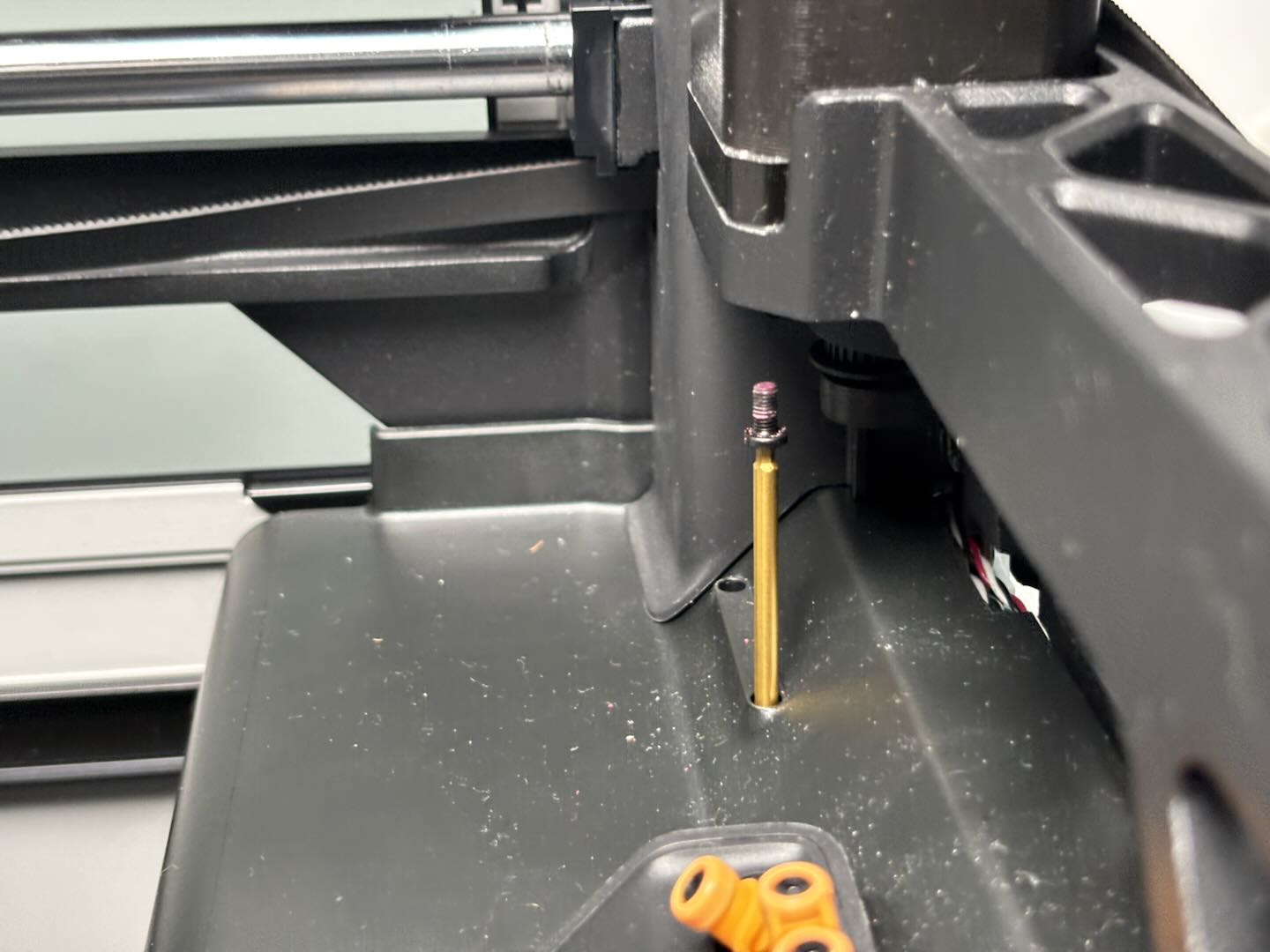
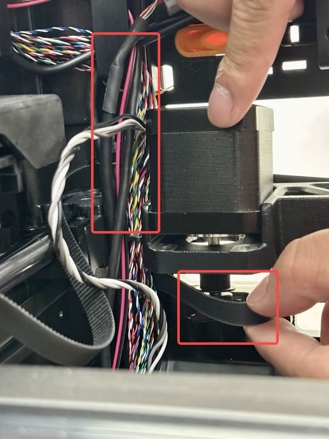
- Remove the magnetic ring from the motor cable.

- Locate the two screw holes on the inner side of the motor through the small holes on the top frame. And puncture the foam if needed, and remove the two inner screws (MK3×6) with a 2.0 mm hex wrench. Then remove the other two front screws (MK3×6) as well.
The top cover includes two small access holes that allow you to reach the inner screws.
Note: Since these screws are quite tight, use a sturdy hex wrench for better torque.
 |
 |
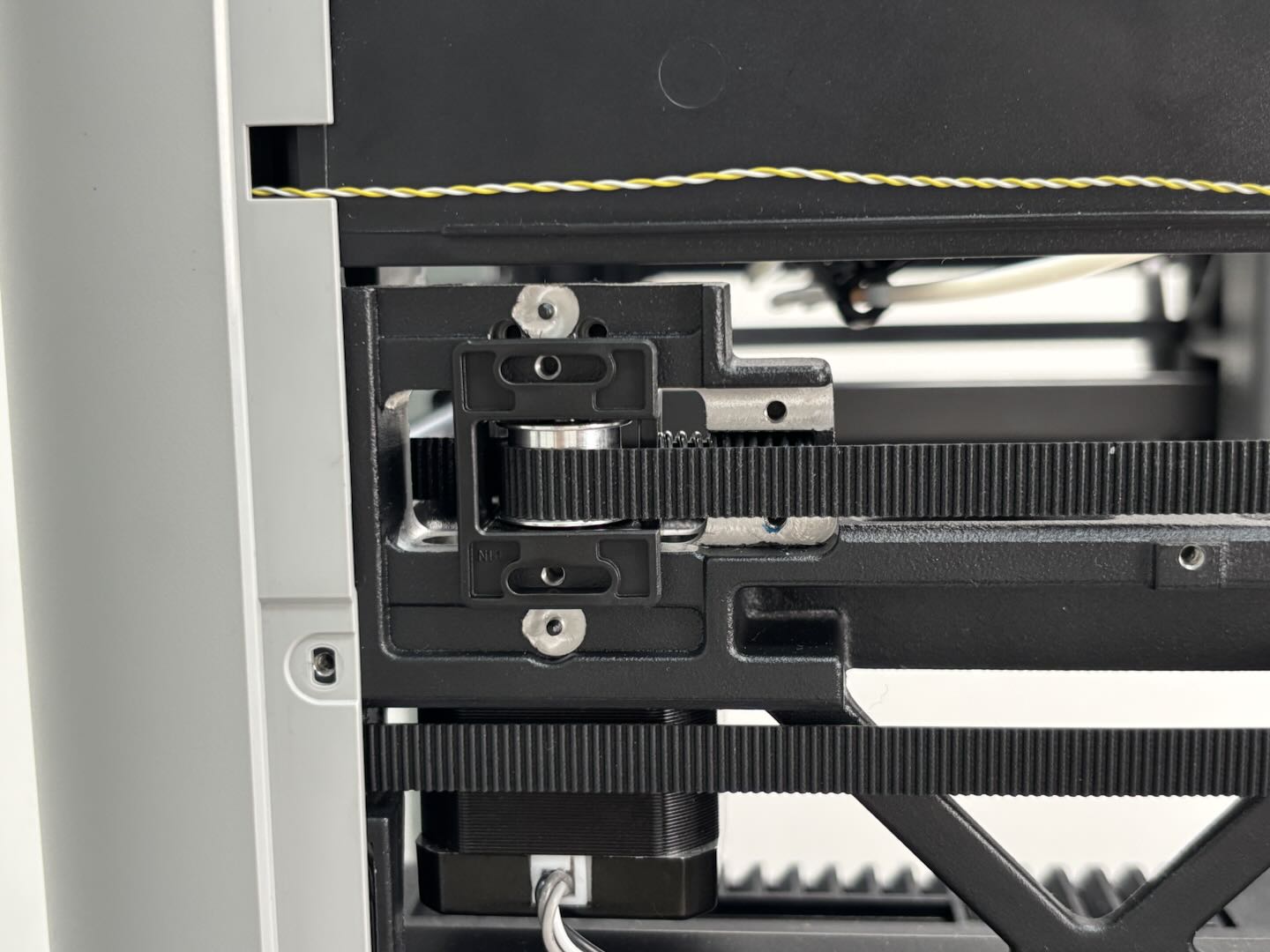
- Remove the two motor bearing bracket screws (M3×6) using an H2.0 Hex Key.

- Pull out the bearing bracket, slip the belt off the motor pulley, then tilt and remove the motor from the frame.

¶ Install X/Y Motor (A)
¶ Step 1:Install X/Y Motor (A)
- Align the motor cable outlet toward the printer's back. And thread the cable through the gap between the inner liner and the frame, then pull it out.

- Insert the motor diagonally through the frame opening, loop the belt onto the motor pulley, and align the bearing bracket notch with the locating pins.
 |
 |
- Tighten the two bearing bracket screws (M3×6) first,
Then the four motor mounting screws (MK3×6)—two at the front, and two at the back is tightened by using a longer H2.0 hex key.
|
|
- Reinstall the magnetic ring on the motor cable.

- Connect the motor cable back to the MC board. Then, make sure the cable is properly routed and secured in the clips to prevent tangling, then reinstall the heatsink.
|
|
¶ Step 2: Reinstall X/Y Tensioner
- Insert the spring into the tensioner bracket shaft.
Place the spring vertically into the frame and push the tensioner leftward until it clicks into place.

- With the thin plate facing outward, align the tension plate holes and tighten the two plate screws (M3×6) and two bracket screws (M3×6) by using a longer H2.0 hex key.
 |
|
¶ Step 3: Reinstall Purge Chute and Rear Panel
Refer to this Wiki guide for detailed steps:
¶ Replace X/Y Motor (B)
¶ Remove the X/Y Motor (B)
¶ Step 1: Remove the Back Panel, Purge Chute, and AC Board Cover
You can follow Replace H2 Series AC Board/AC board Cover to remove them in sequence:
-
Back Panel
-
Purge Chute
-
AC Board Cover
Since replacing the X/Y Motor (B) doesn’t involve the AC board itself, you can skip the AC board replacement steps in this article:
¶ Step 2:Remove the X/Y Tensioner
- Use an H2.0 hex key to remove the two tensioner plate screws (M3x6) and the two bracket screws (M3x6).

- Firmly push the X/Y tensioner out from its latch.

¶ Step 3: Remove the AP Board Cover and Cable Guard
- Use an H2.0 hex key to remove one screw (BT2.6x8), then lift the AP board cover from the side near the front door.
 |
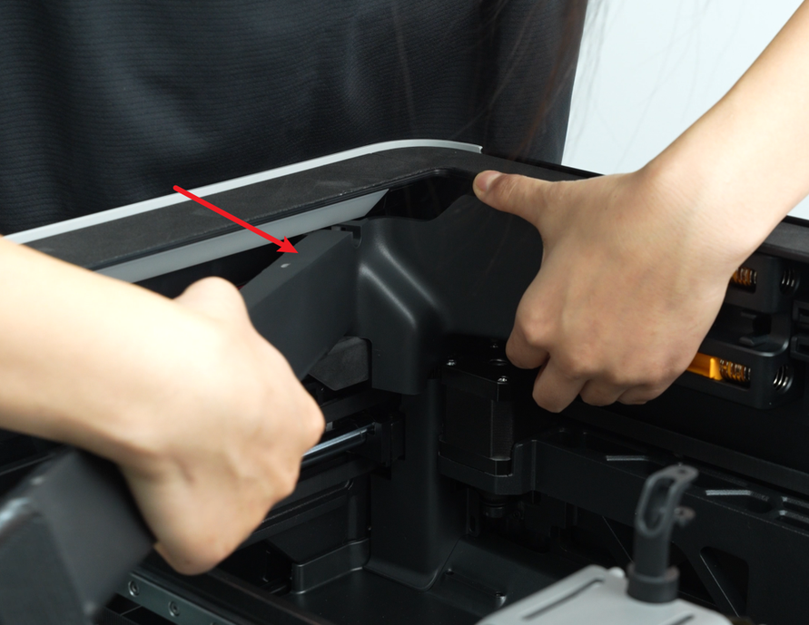 |
- Unclip the cable guard from the right side and cut the zip ties securing the wiring harness.
 |
 |
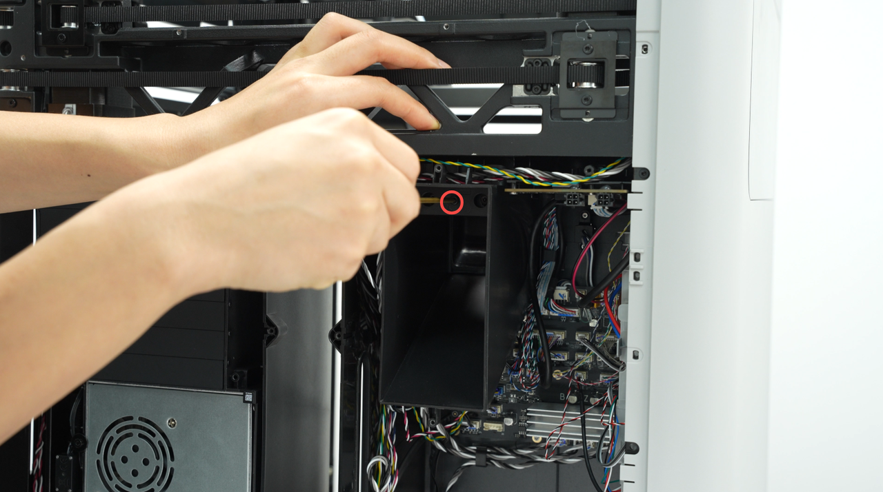
¶ Step 4: Remove the 4-Pin Interface Board
To make it easier to access the X/Y Motor (B), there is a small opening at the top of the left inner panel (behind the 4-pin interface board).Thus, please remove the 4-pin board first.
Disconnect the cables from the 4-pin interface board, then use an H1.5 hex key to remove the two screws (BT2x5) and take out the board.
 |
 |
¶ Step 5: Remove the X/Y Motor (B)
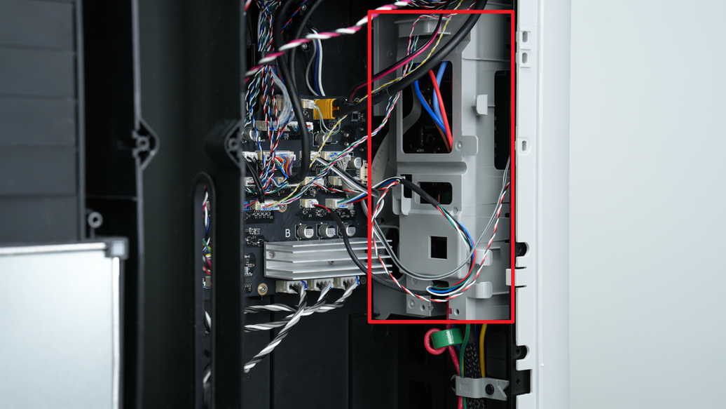
- Disconnect the motor cable connector. If the MC board heatsink blocks access, remove its two screws and take it off temporarily. Then unplug the motor cable from the MC board and remove the cable from the wire channel.
|
 |
The blue compound at the bottom of the heatsink is thermal paste. Do not remove it.
- Remove the magnetic ring from the motor cable.
- Insert an H2.0 hex key through the small hole at the top of the left inner panel to remove the four motor mounting screws (MK3x6).
 |
 |
- Use an H2.0 hex key to remove the two bearing bracket screws (M3x6).

- Slide the bearing bracket out from the frame, remove the belt from the pulley, then tilt the motor slightly and take it out from the frame.

¶ Install the X/Y Motor (B)
¶ Step 1: Install the Motor
- Feed the motor cable through the inner panel's wire channel. Align the motor's cable outlet with the channel, tilt the motor through the frame opening, loop the belt over the pulley, and insert the bearing bracket into the frame slot.
- Use an H2.0 hex key to tighten the two bearing bracket screws (M3x6).
- Insert an H2.0 hex key through the inner panel hole to position and tighten the four motor screws (MK3x6).
|
|
- Reinstall the magnetic ring on the motor cable.
- Connect the motor cable to the MC board, secure the cable in the clips to avoid tangling, and reinstall the heatsink.
|
|
¶ Step 2: Reinstall the 4-Pin Interface Board
Place the 4-pin interface board back in position, tighten the two screws (BT2x5) with an H1.5 hex key , and reconnect the cables.
|
|
¶ Step 3: Reinstall the AP Board Cover and Cable Guard
- Bundle the wiring harness with a zip tie and reinstall the cable guard. Please make sure no wires are exposed after installation.
|
 |
If you don’t have a zip tie, you can skip this step—just make sure all wires are safely tucked inside the guard.
- Insert the AP board cover from the rear side and tighten the screw (BT2.6x8) using an H2.0 hex key.
|
|
¶ Step 4: Reinstall the X/Y Tensioner
- Insert the spring onto the tensioner bracket shaft, place it vertically into the frame, and push the tensioner to the left until it snaps into place.

- Make sure the thin metal plate faces outward. Then, align the tensioner plate with the screw holes and tighten the two plate screws (M3x6) and two bracket screws (M3x6) with a 2.0 mm hex wrench.
¶ Step 5: Reinstall the Back Panel, Purge Chute, and AC Board Cover
You can follow Replace H2 Series AC Board/AC board Cover to reinstall them in sequence:
-
Back Panel
-
Purge Chute
-
AC Board Cover
¶ How to Verify the Installation
Connect the power and turn on the printer. Initiate a print and check for any error messages.
¶ End Notes
We hope this guide has provided clear and practical support.
If the issue remains unresolved, please submit a support ticket and include your recent printer logs and additional pictures or other details. Our technical team will review your request and provide detailed assistance.
You can also visit Bambu AI, which can instantly answer common questions and provide you with operational guidance.