¶ Servomotor Replacement for H2D
The servomotor is one of H2D's key actuators, primarily used to drive the opening/closing actions of the air filter and chamber exhaust. By receiving signals from the MC board, the servomotor achieves precise angular positioning, ensuring accurate operation of both the filter switch flap and chamber exhaust for effective air circulation and exhaust control.
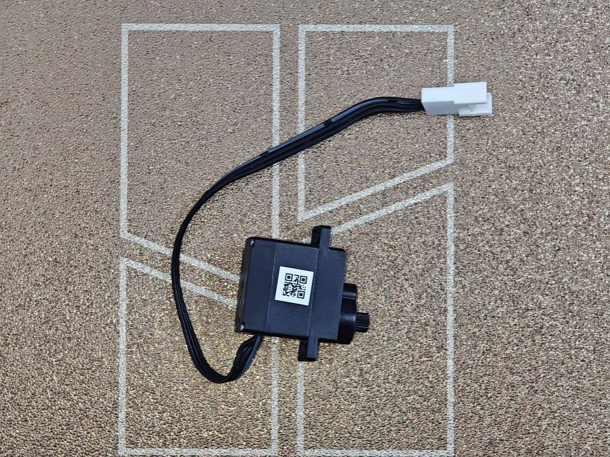
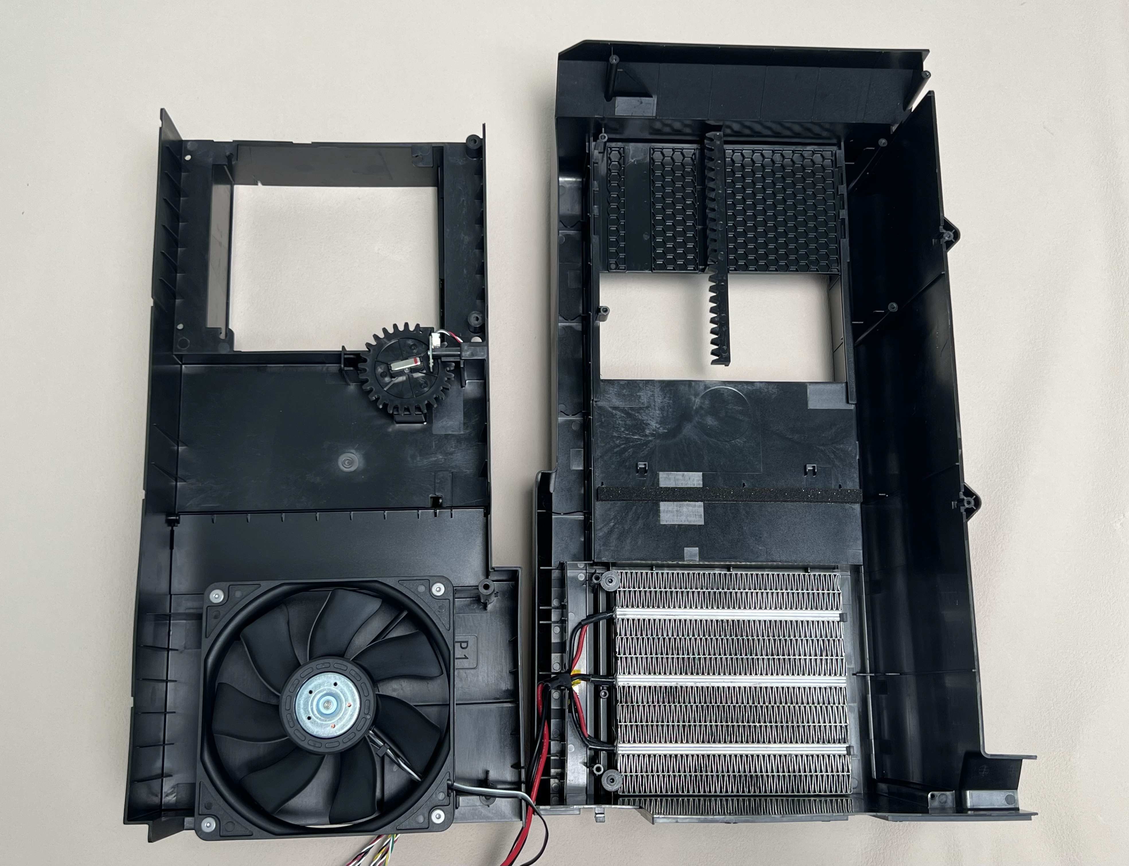
If your spare part is the entire right inner lining upper cover, you may remove the new servomotor from it for individual replacement. The servomotor is located on the back side of the right inner lining.
¶ Applicable models of printers
Bambu Lab H2D
¶ When to Replace
Replacement is necessary when the servomotor malfunctions or fails, such as when the filter switch flap or exhaust fails to open/close properly, operates sluggishly/unsteadily, or completely stops responding to control signals.
¶ Tools and materials needed
- H2.0 Allen key
- H1.5 Allen key
- 25 minutes
¶ Safety Warning
important!
It's crucial to power off the printer before conducting any maintenance work, including work on the printer's electronics and tool head wires. Performing tasks with the printer on can result in a short circuit, leading to electronic damage and safety hazards.
During maintenance or troubleshooting, you may need to disassemble parts, including the hotend. This exposes wires and electrical components that could short circuit if they contact each other, other metal, or electronic components while the printer is still on. This can result in damage to the printer's electronics and additional issues.
Therefore, it's crucial to turn off the printer and disconnect it from the power source before conducting any maintenance. This prevents short circuits or damage to the printer's electronics, ensuring safe and effective maintenance. For any concerns or questions about following this guide, open a new ticket in our Support Page and we will do our best to respond promptly and provide the assistance you need.
¶ Replace the Filter Switch Flap Servomotor
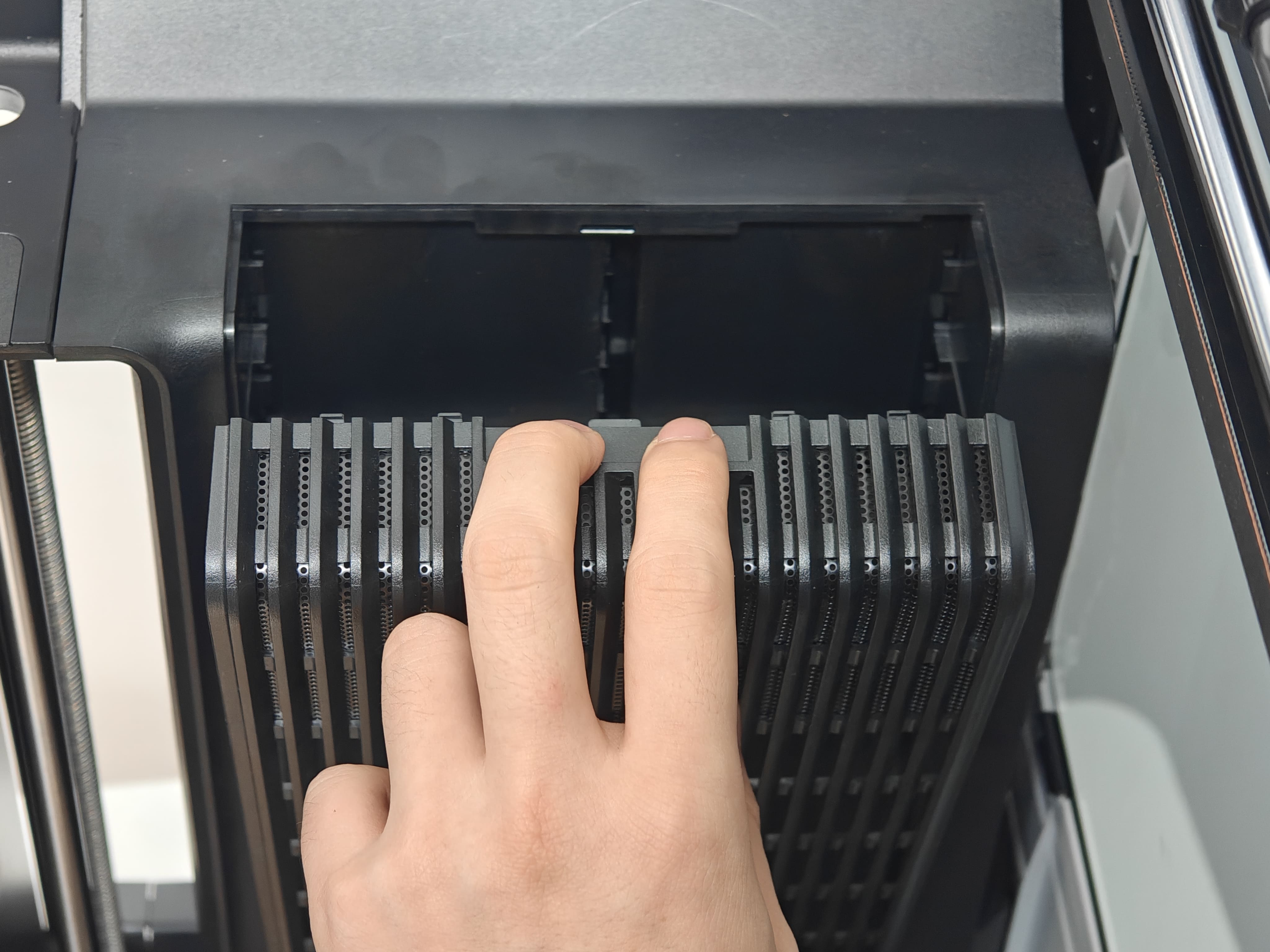
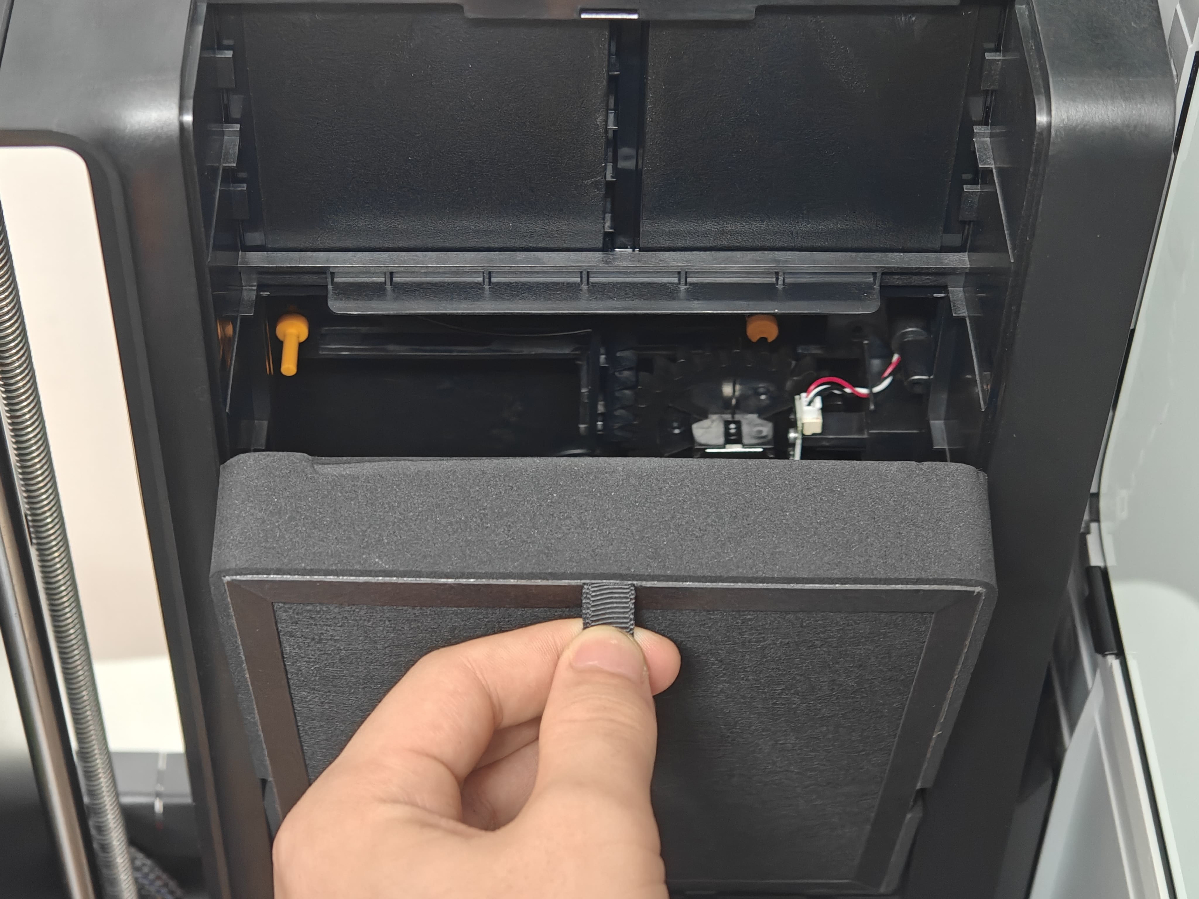
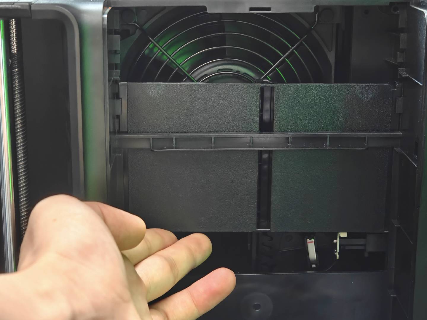
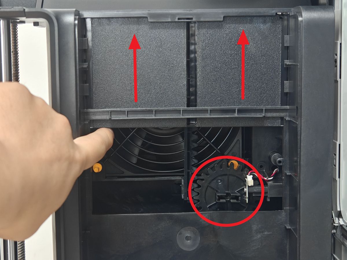
¶ 1.Remove the Air Filter Cover and Air Filter
Grasp the top slot and gently pull backwards to remove the filter cover, then remove the filter in the same manner.
 |
 |
¶ 2.Remove the Gear Magnets
Use an H1.5 Allen key to remove the magnets from the gear groove. Exercise extreme caution to prevent magnets from falling into the chassis.
 |
 |
If the filter switch flap remains at the bottom after removing the air filter, manually lift it slowly to the top position.
¶ 3.Remove the Gear
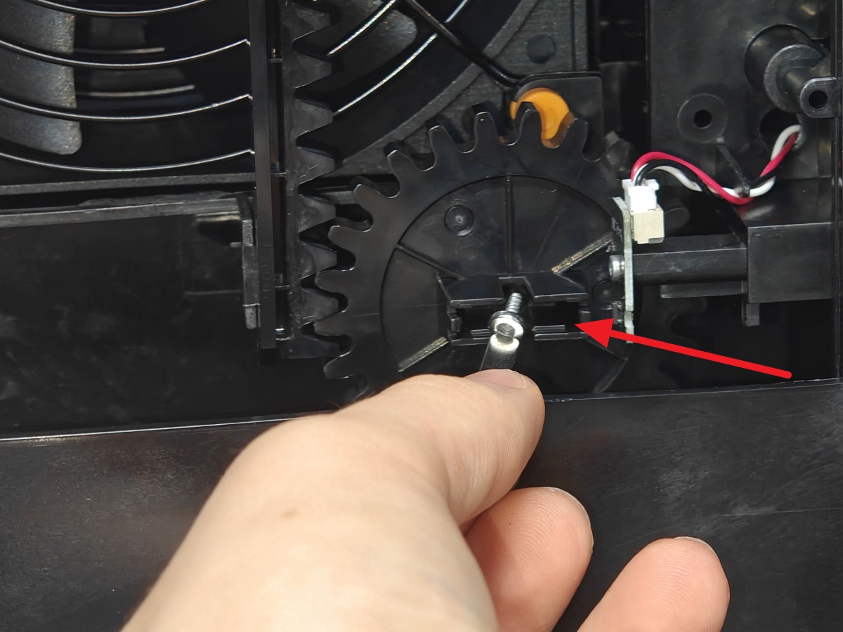
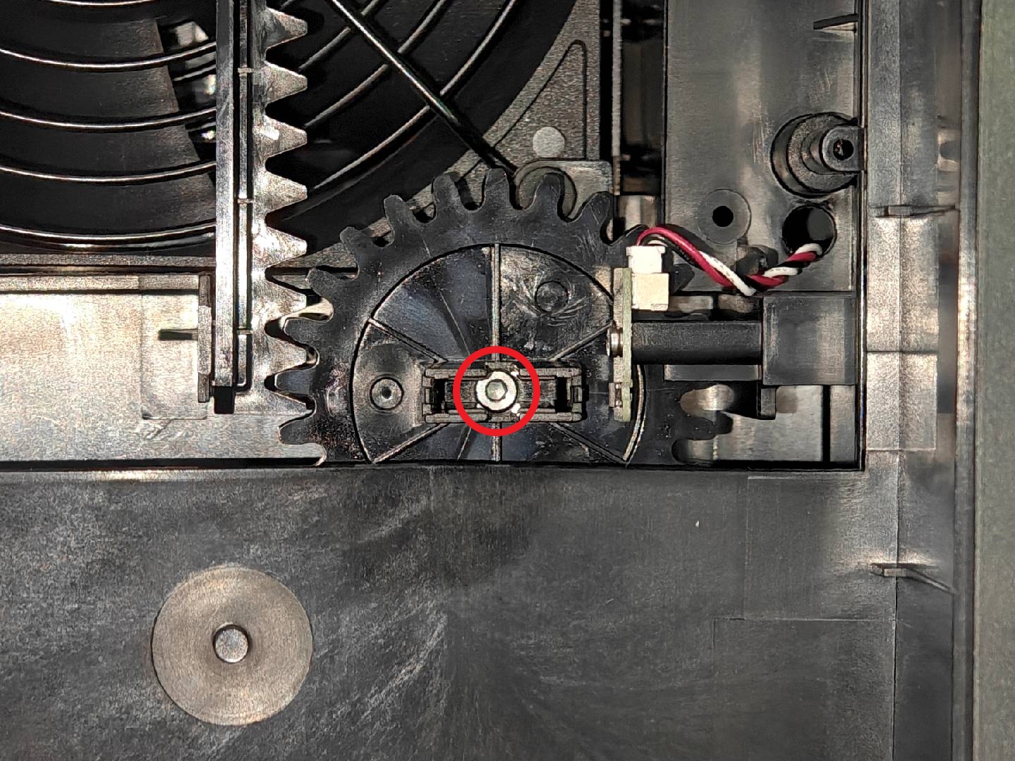
Loosen the fixed screw securing the gear to the servomotor shaft.
To prevent screws from falling into the chassis during removal, use a magnet to slowly extract them, avoiding the hassle of retrieving small components.
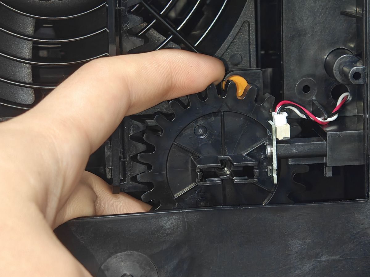
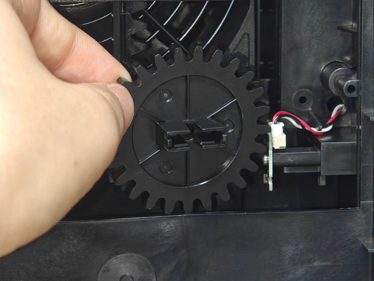
After removing the fixing screws of the gear and servo shaft, take off the gear.
 |
 |
¶ 4.Remove the Rear Board
Since the filter switch flap servo is installed inside the chamber, removing and installing it requires removing the printer's rear panel. Next, you need to move to the rear of the printer. You can refer to this guide to remove the printer's rear panel.
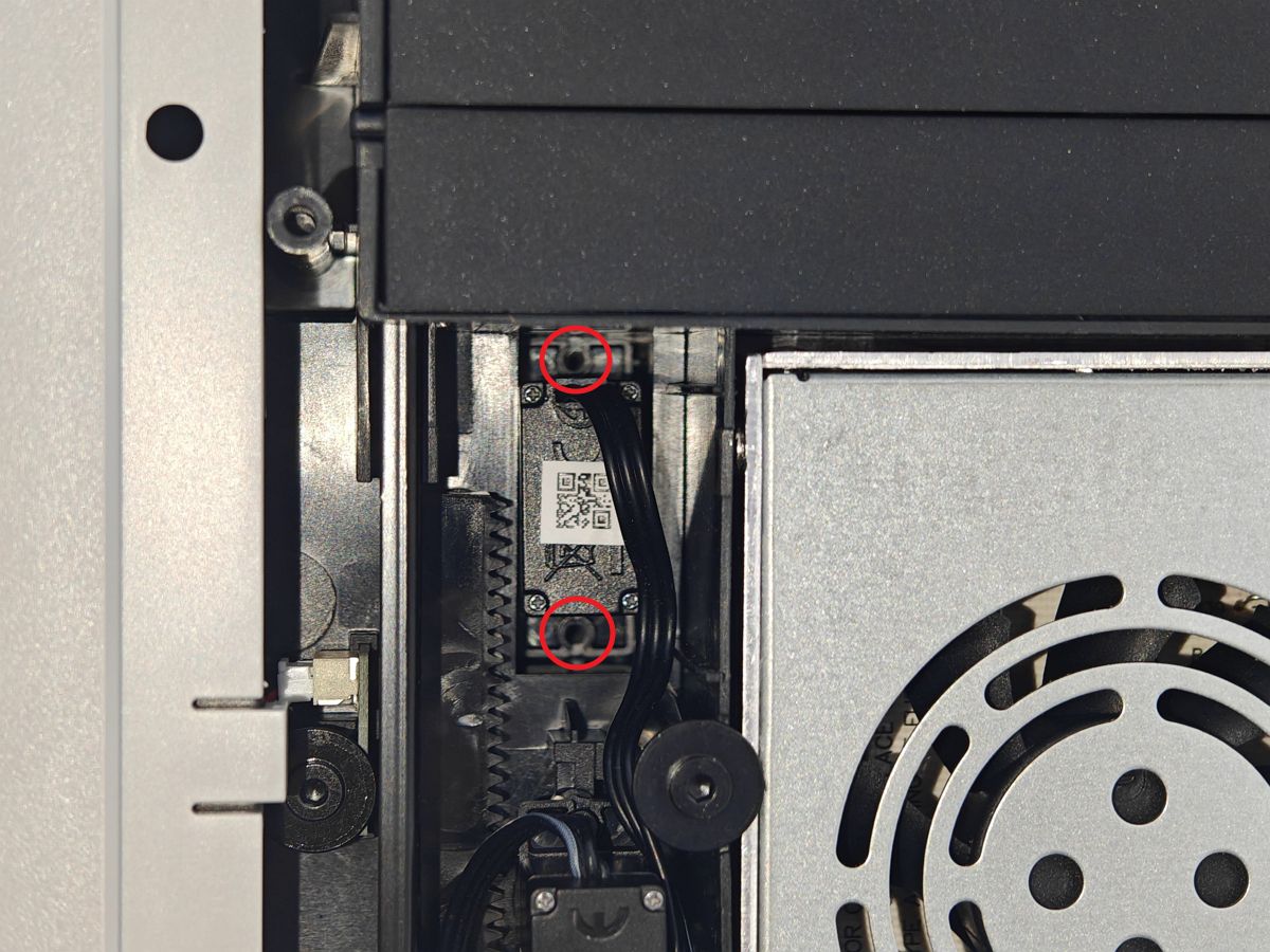
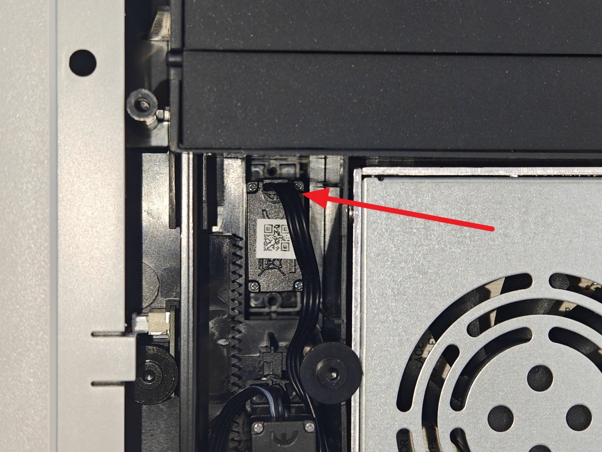
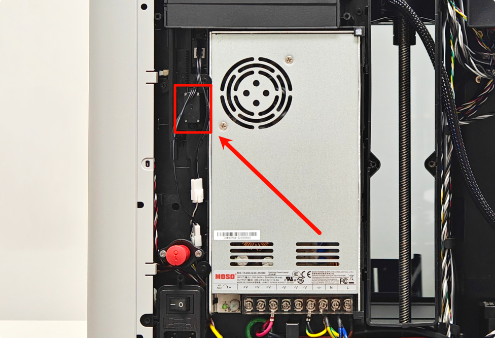
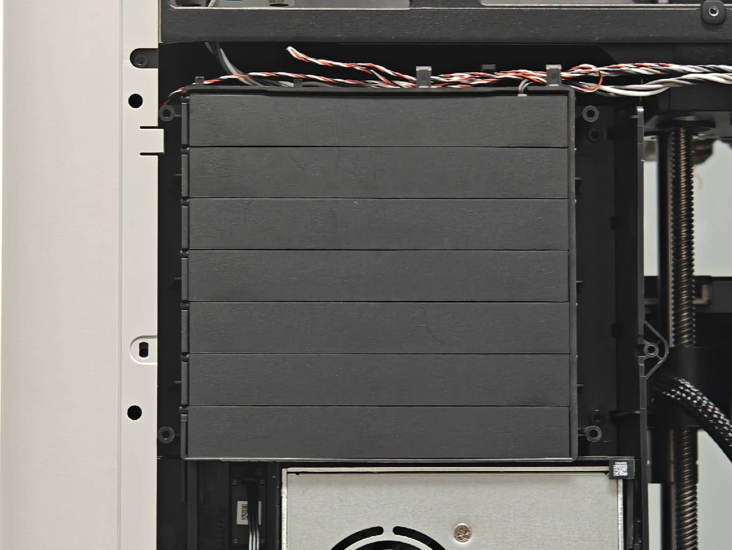
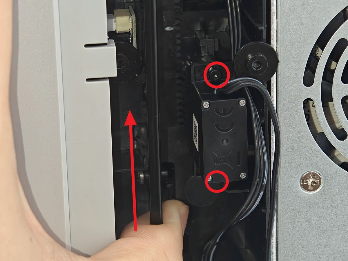
The filter switch flap servo is located at the top left of the internal power supply and below the chamber exhaust.
.jpg)
¶ 5.Remove the Filter Switch Flap Servomotor
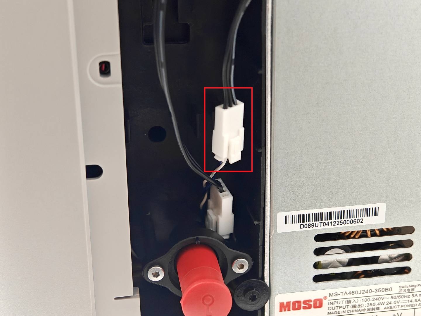
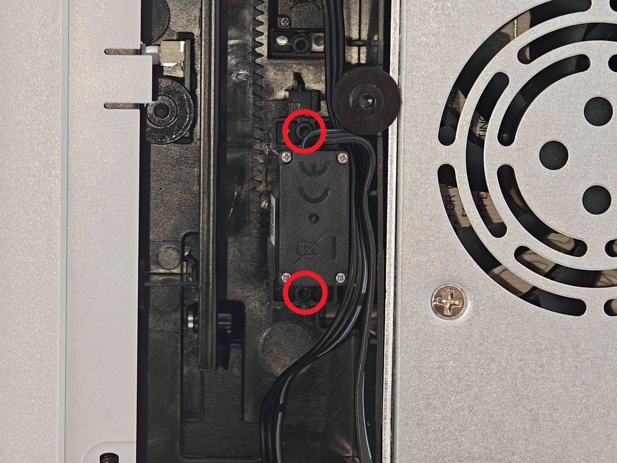
Remove both upper and lower fixed screws (BT2-8), then disconnect the servomotor cable. Similarly, use a magnet to prevent screws from falling into the chamber.
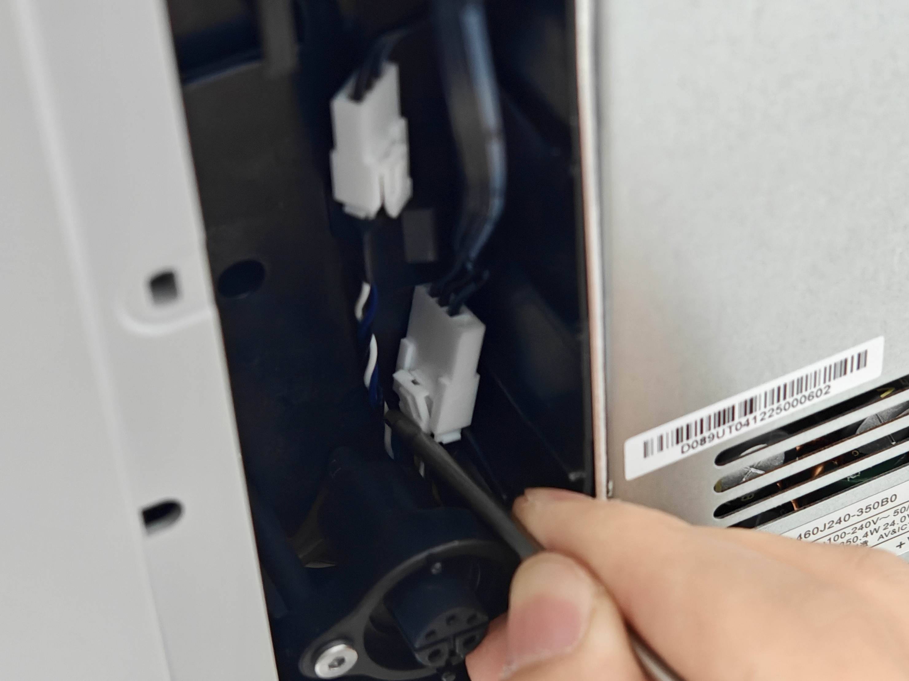
Press the connector lock to disconnect the servo cable.
¶ 6.Install the New Filter Switch Flap Servomotor
During installation, ensure the cable faces upward. Initially secure the first screw without full tightening. After both screws are positioned, uniformly tighten them together to ensure stable installation without misalignment.
After installing the servomotor, connect its cable.
¶ 7.Install the Gear
When installing the gear, press it onto the servomotor output shaft while ensuring the filter switch flap is at its highest position to guarantee proper initial alignment between gear and servomotor.
|
 |
After gear installation is complete, proper alignment is confirmed when both gear surfaces are flush.

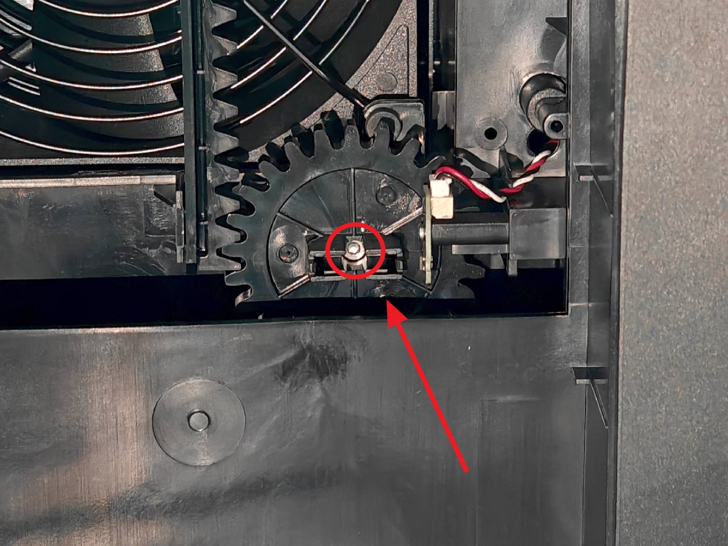
¶ 8.Install Screws and Magnets
Next, install the fixed screw to secure the gear to the servomotor shaft (avoid over-tightening). After installation, ensure the magnet slot on the gear remains horizontal.
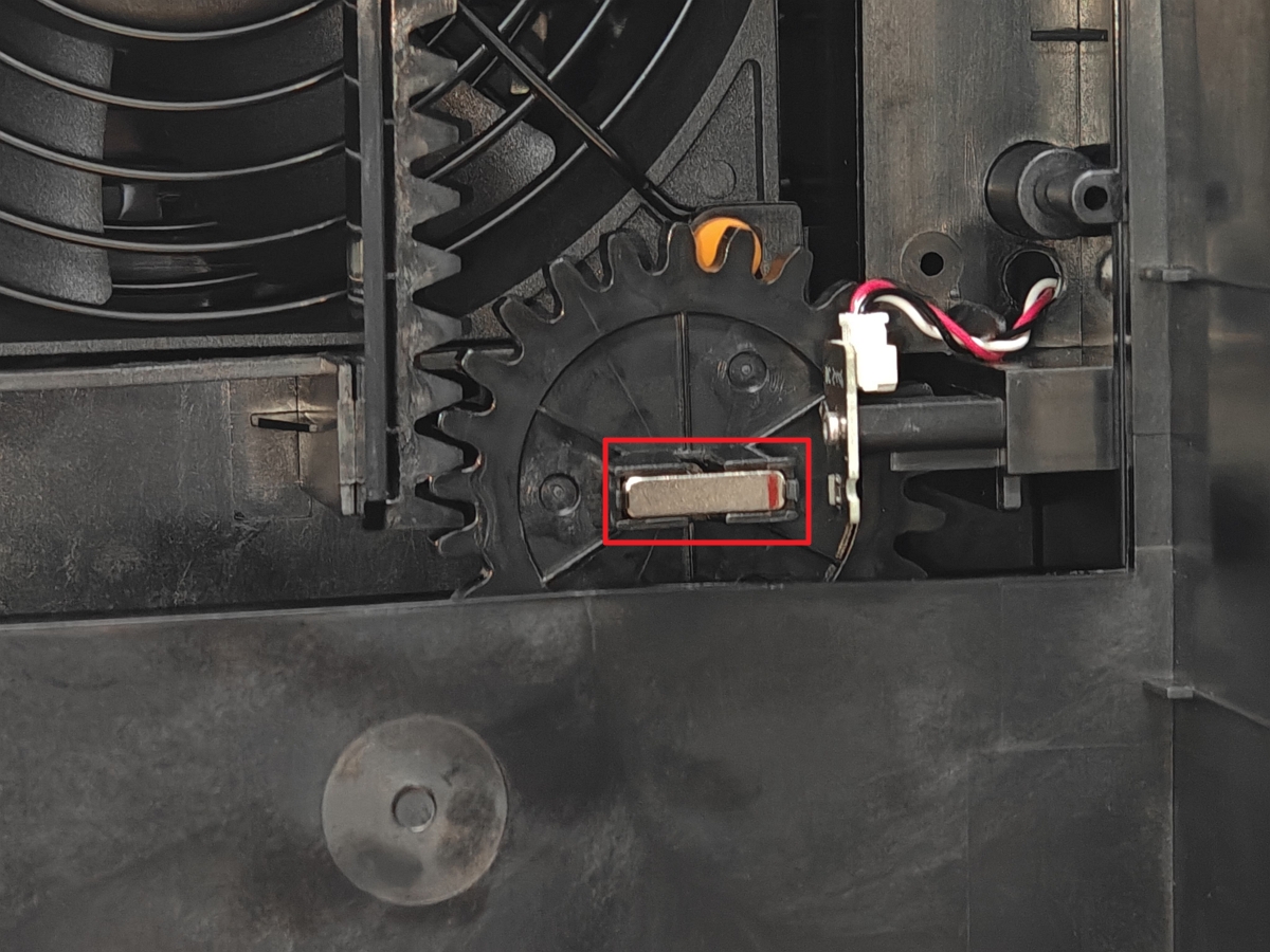
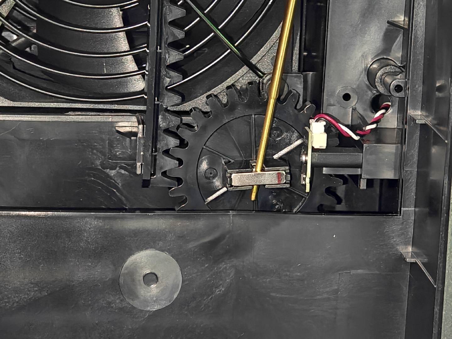
When installing the magnet, align the red-marked end precisely with the hall sensor (as shown below) to ensure accurate signal recognition and proper system operation.
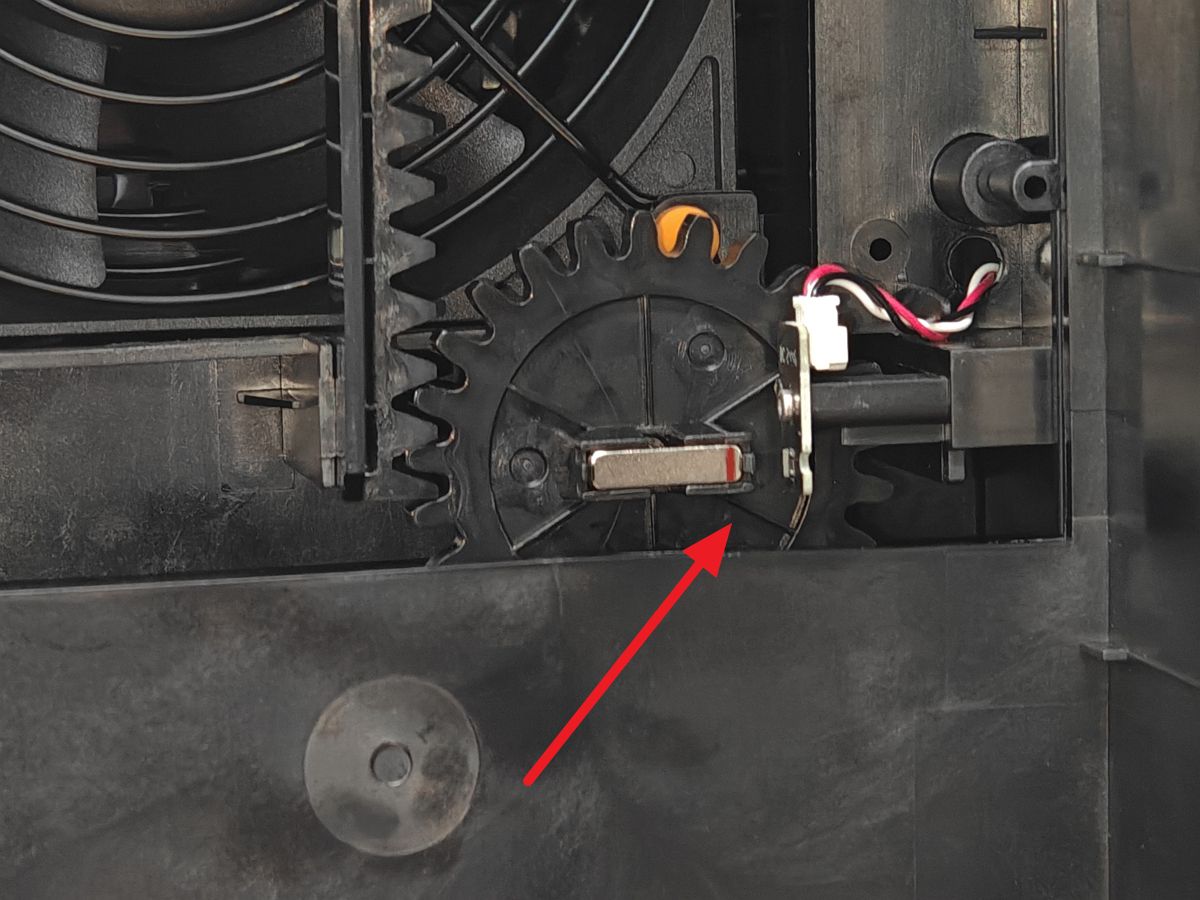
Note: The magnet must remain horizontal with its red-marked end precisely facing the hall sensor. Improper installation may cause the filter switch flap servomotor to experience missing steps, preventing proper opening/closing of the flap and affecting system operation.
¶ 9.Install the Rear Board
After completing the replacement of the filter switch flap servo, you can install the rear panel back onto the printer.
If you need to continue replacing the chamber exhaust servo, you can wait until you have finished replacing the chamber exhaust servo before installing the rear panel.
¶ Replace the Chamber Exhaust Servomotor
¶ 1.Remove the Rear Board
Since the chamber exhaust servo is installed inside the chamber, removing and installing it requires removing the printer's rear panel. Next, you need to move to the rear of the printer. You can refer to this guide to remove the printer's rear panel.
¶ 2.Remove the Chamber Exhaust Servomotor
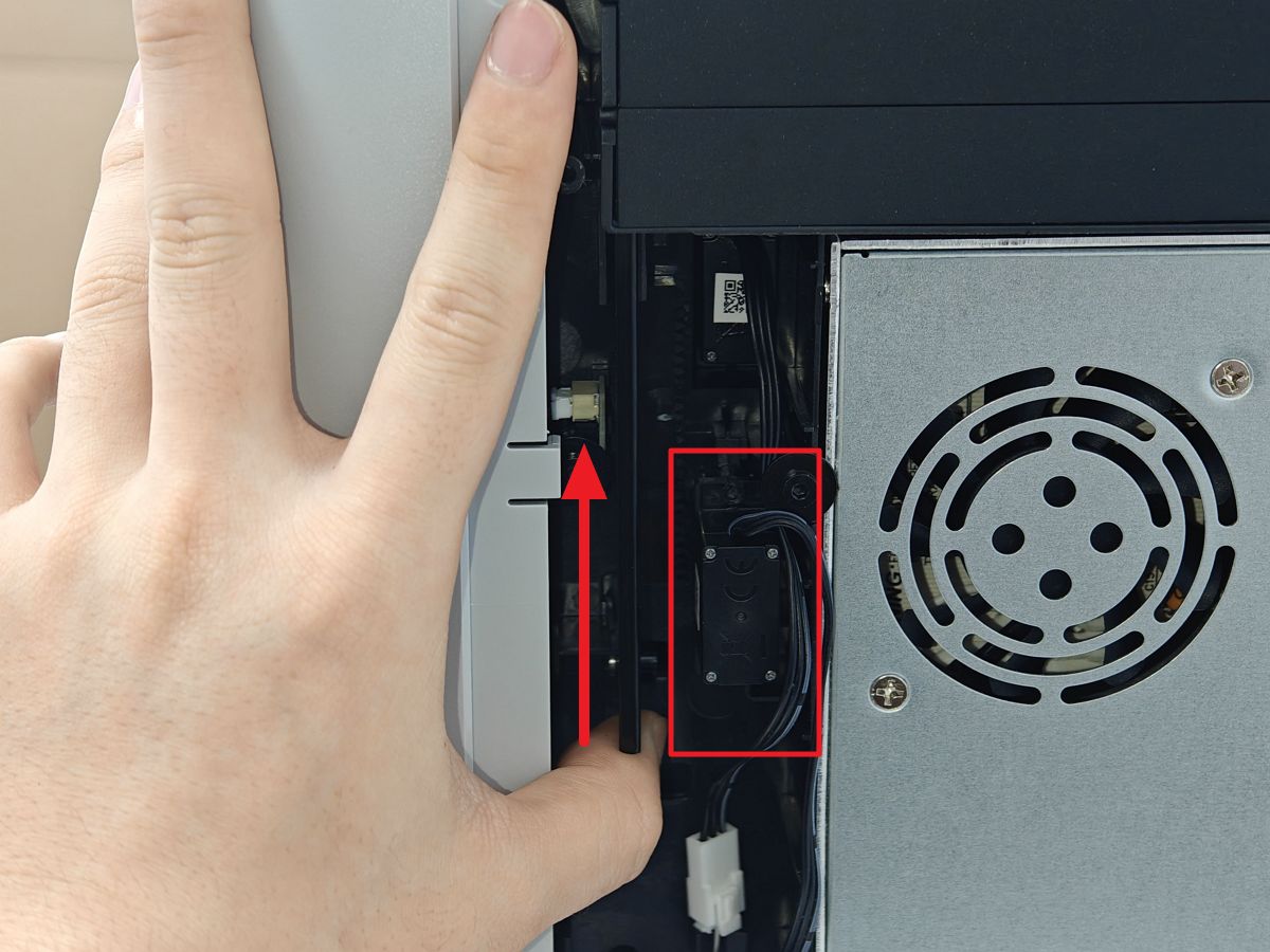
The chamber exhaust servo is located to the left of the internal power supply and below the filter switch flap servo.
Remove both upper and lower fixed screws from the servomotor.
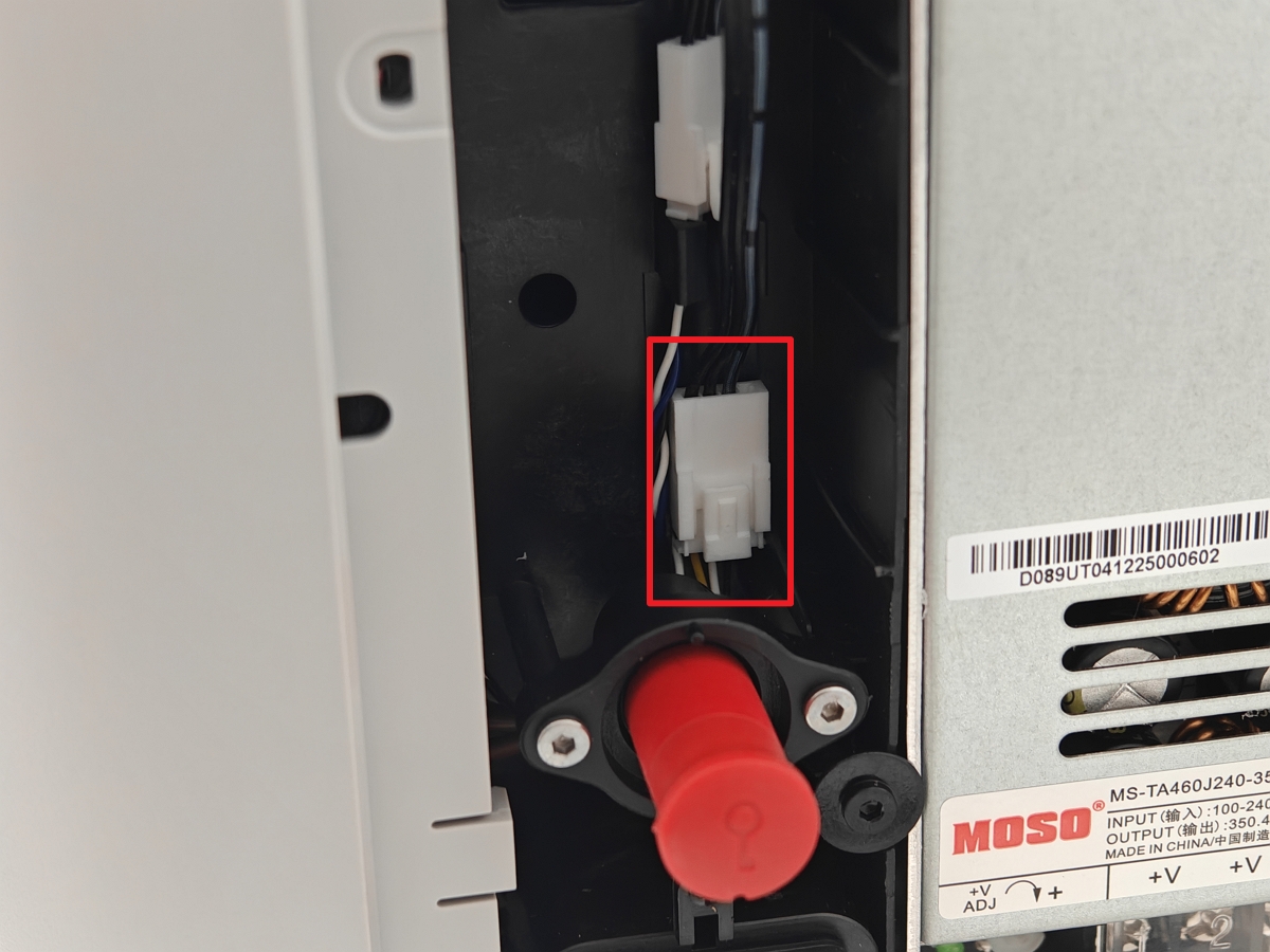
¶ 3. Disconnect the Cable and Remove the Servomotor
When disconnecting the cable, press the connector's release tab while gently pulling to avoid damaging the connector or cable.
¶ 4.Remove the Servomotor Gear
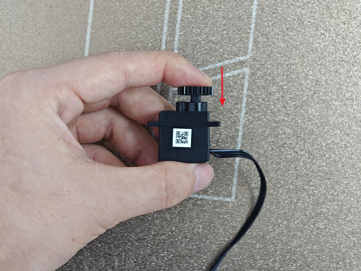
After removing the servomotor, first remove the fixed screw from the servomotor shaft, then detach the gear.
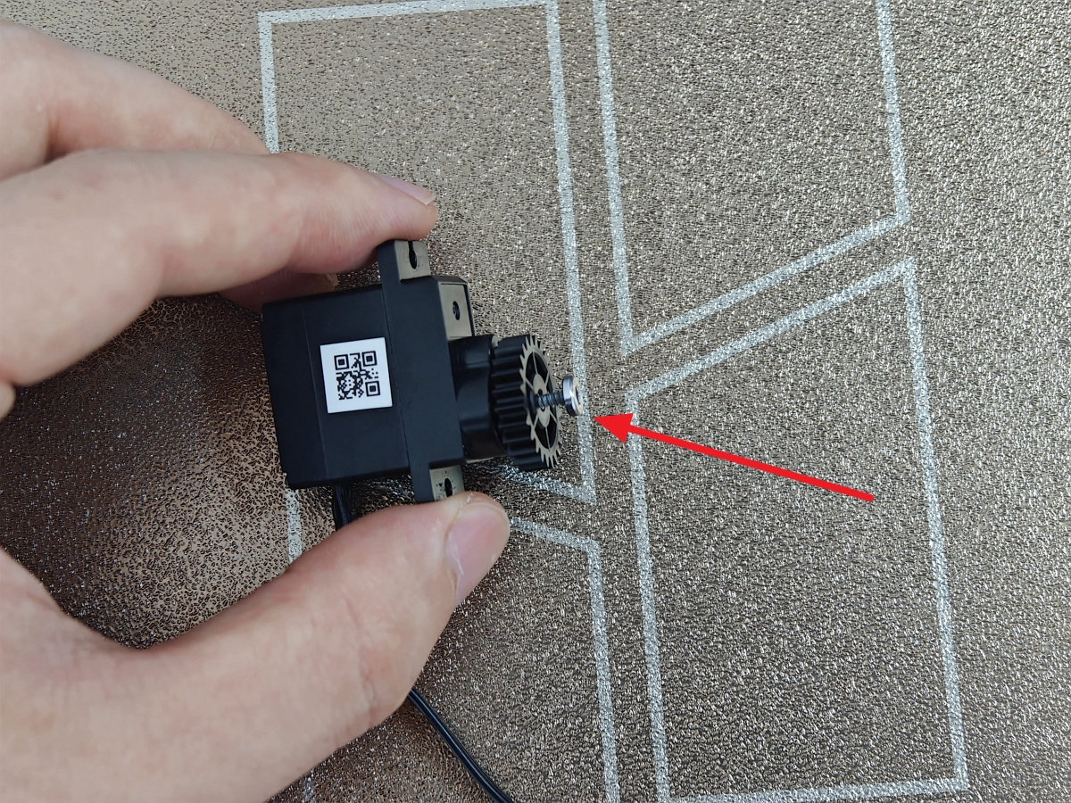
¶ 5.Install the Gear on New Servomotor
Install the gear onto the new servomotor shaft and secure it with the fixed screw.
Note: Apply moderate torque when tightening the screw. Excessive force may strip the threads, affecting stability and future maintenance.
¶ 6. Install the Servomotor
During installation, lift the active chamber exhaust gear upward while ensuring the chamber exhaust remains in the closed position. While holding the gear in place, install the fixed screws.
First install both upper and lower screws without full tightening. After both screws are positioned, evenly tighten them together to ensure stable installation without misalignment.
 |
 |
Note: Ensure the servomotor cable faces upward and confirm the chamber exhaust is closed. Improper installation may cause servomotor missing steps, preventing proper opening/closing of the chamber exhaust.
¶ 7.Connect the Servomotor Cable
Carefully insert the cable connector until you hear or feel the plastic latch click into place.
¶ 8.Install the Rear Board
After completing all installations, it is recommended that you skip this step and verify the functionality, to confirm that the servo functions are normal together before installing the printer's rear panel.
¶ Verify the functionality
¶ Filter Switch Flap Servomotor Verification
Power on the printer, access the control interface, select Air Condition System, then set Cooling Mode to Heating. Correct installation is confirmed when observing normal upward/downward movement of the filter switch flap.

If the flap fails to move properly, refer to Steps 7 and 8 to verify:
- The flap was at its highest position during installation
- The magnet remains horizontal with its red-marked end facing the hall sensor
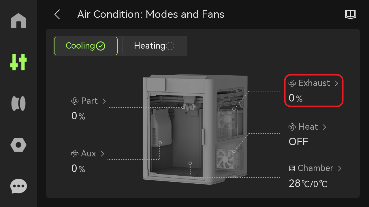
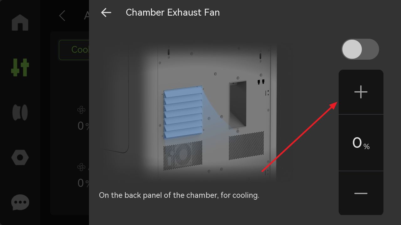
¶ Chamber Exhaust Servomotor Verification
Power on the printer, navigate to Air Condition System => Cooling Mode => Exhaust. Correct installation is confirmed when observing normal opening/closing of the chamber exhaust.
 |
 |

If the chamber exhaust fails to open or close properly, please refer to step 6 to verify the following:
- The chamber exhaust was in the fully closed position during installation
- The servomotor gear properly engages with the exhaust rack
¶ End Notes
We hope the detailed guide provided has been helpful and informative.
If this guide does not solve your problem, please submit a technical ticket, we will answer your questions and provide assistance.
If you have any suggestions or feedback on this Wiki, please leave a message in the comment area. Thank you for your support and attention!