This page is an introduction to the main components of the Bambu Lab H2D printer so that you can have a general understanding of this printer.
¶ How does H2D work?
The H2D series printer is a machine that uses plastic filament to create 3D objects.
In most cases, H2D can print 3D models in STL format, and the file model needs to be pre-processed using slicing software before printing.
Taking Bambu Studio as an example, the slicing software divides the STL file into multiple layers. The information of each layer is automatically converted into a language that the printer can understand, which is used to guide the movement paths and speeds of each axis during the printing process.
In addition, the slicing software can also integrate a variety of parameter settings in the generated code, such as the printing temperature of the filaments, the extrusion speed of the printer, and generate support for certain parts of the printed model.
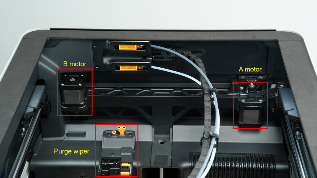
¶ Core XY Movement System
Bambu Lab H2D is based on the Core-XY architecture, which contains two stepper motors and multiple sets of idler pulleys on the XY plane. Each stepper motor is connected to the toolhead through an independent timing belt, and the movement and position of the toolhead are controlled by the motor-timing belt coordinated transmission.
H2D prints faster with the CoreXY movement system than with traditional Cartesian printers because it is lighter, which is important for fast printing.
For more information on the CoreXY movement system, visit this link.
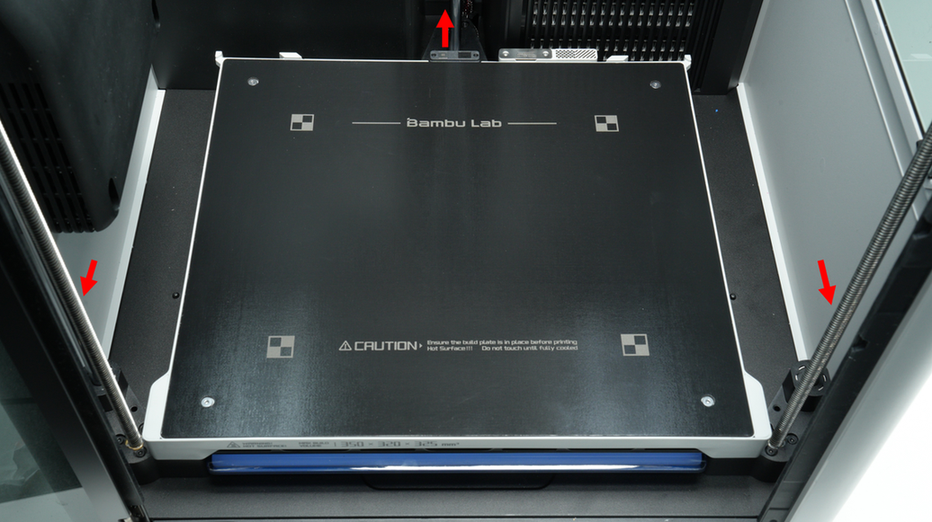
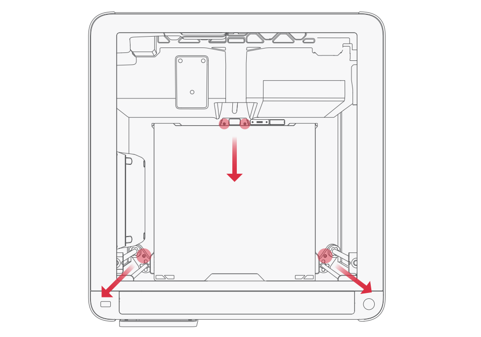
¶ Z-axis
The Z-axis of the printer consists of 3 lead screws, which are connected to the Z-axis stepper motor through a belt.
H2D has been pre-calibrated for bed leveling at the factory. Before use, please follow the instructions to remove the 4 screws that fix the Z-axis to the base. Please keep these 4 screws. If the Z-axis lead screw is disassembled and maintained or the machine is transported later, these 4 screws need to be locked back.
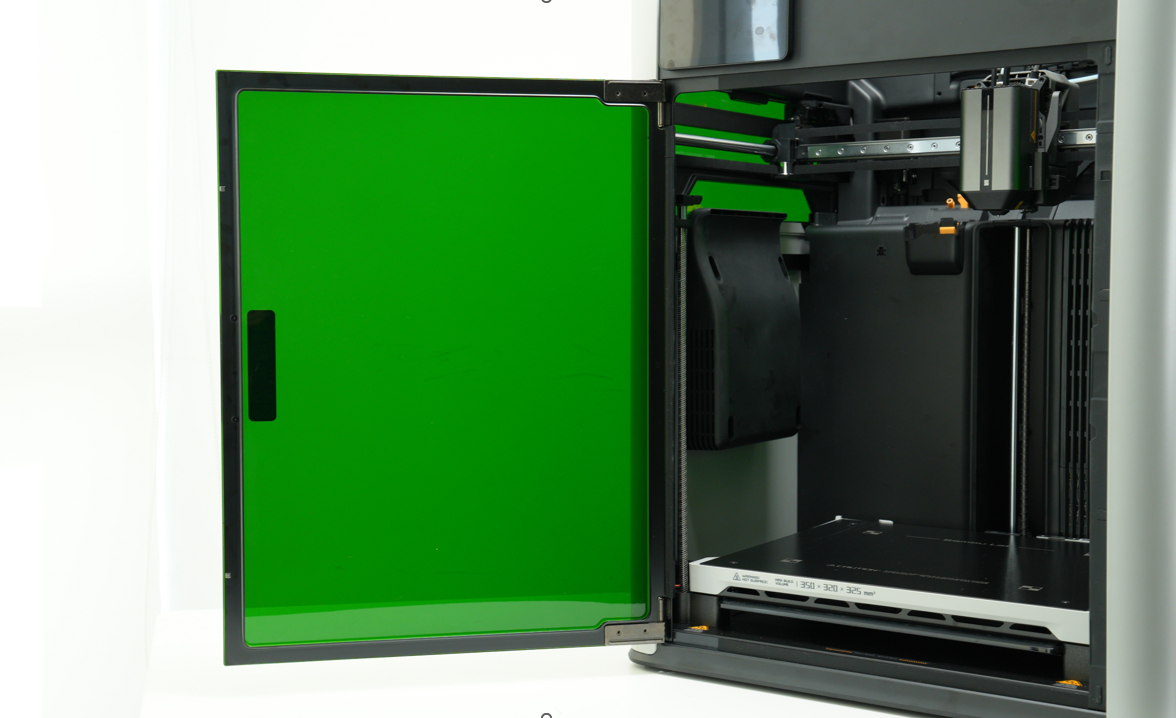

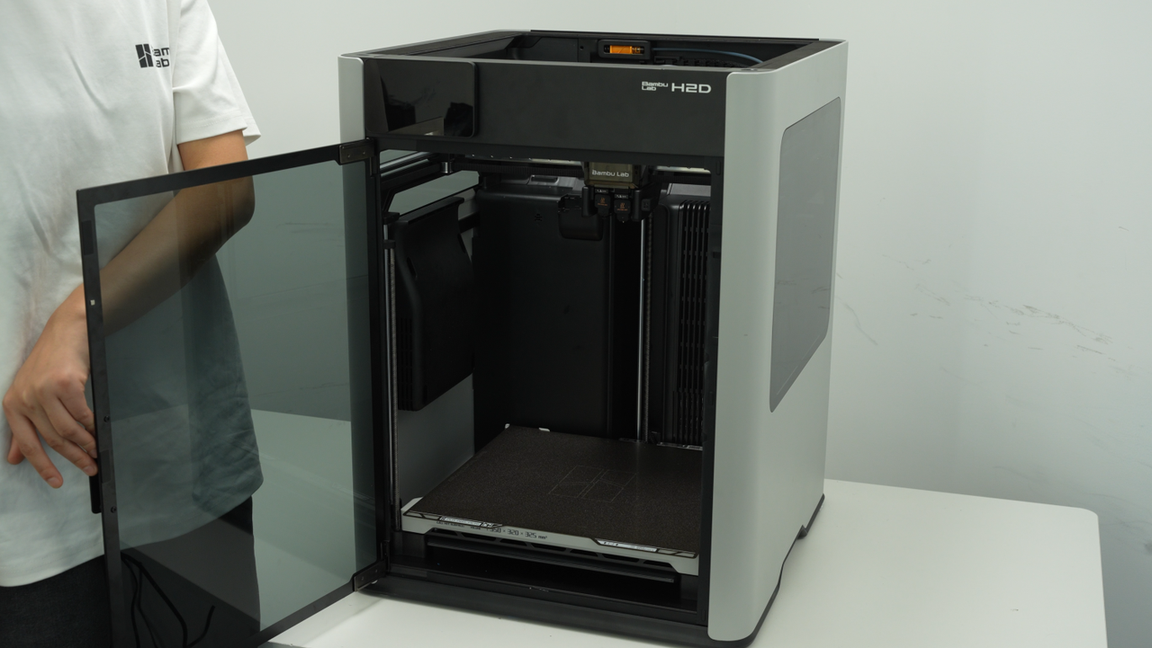
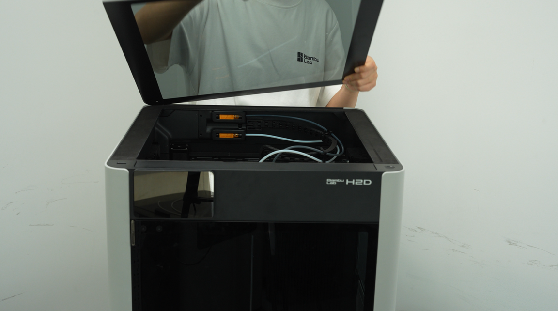
¶ Printer Housing
H2D printers offer two material options for the top cover, front door, and side panel windows: tempered glass version and laser safety version.
If you need to use a laser module, you must choose the laser safety glass the laser version of the printer comes pre-installed with the laser safety version, while the non-laser version requires a separate upgrade kit (available after the main unit's launch date), which includes a green PC front door and left and right windows, as well as a black top protective cover. Otherwise, the laser function will be forced to stop automatically.
H2D has equipped the top cover, front door, side panels, and side panel windows with an open door detection function. When it is detected that the "door" is opened, if a laser module is installed, the device will pop up a red error prompt and immediately suspend the task. If a non-laser function is used, the device will prompt "Open the door" in HMS and pop up an orange warning prompt, but will not suspend the task.
¶ Extruder
The extruder is responsible for pulling the filament out of the spool and feeding it into the hotend. After heating and melting, it is extruded through the nozzle to generate a printed model.
The extruder needs to accurately control the length of extrusion and retraction of the filament to ensure the dimensional accuracy and appearance quality of the printed model. It is one of the core components of a 3D printer.
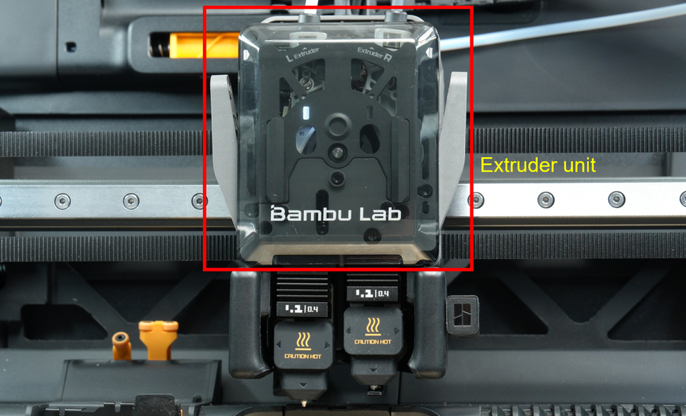
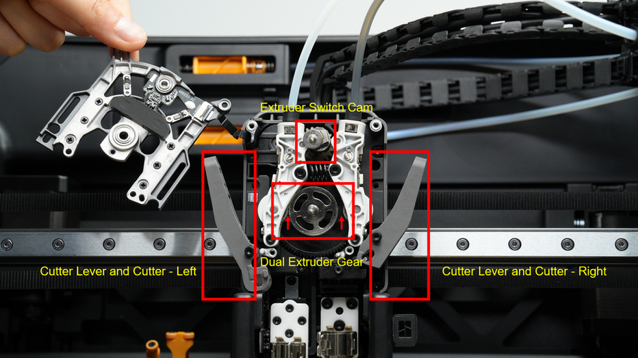
H2D's extruder is mainly composed of a switching system, extrusion system, and cutter system:
The switching system uses a switching motor and drive system to drive the cam, which achieves the oscillating movement of the left and right driven wheel linkages (driven rods). Paired with the tension spring connecting the driven rods, one side's driven wheel presses against the extrusion driving wheel on the extrusion system to compress the filament, allowing the wheel to rotate and extrude the filament. Meanwhile, the driven wheel on the other side does not press against the filament, so the rotation of the active wheel does not cause any movement of the filament.
The extrusion motor drives the extrusion driving wheel to rotate clockwise or counterclockwise, which can drive the driven wheels on both sides to extrude the filament respectively, to achieve the effect of left or right extrusion with one extrusion driving wheel.
The cutter system cuts the filament between the extruder and the hotend, and the filament can be pulled back at this time. Combined with the filament cutter stopper and AMS, the printer can automatically cut and switch filaments to achieve multi-color or multi-material printing.
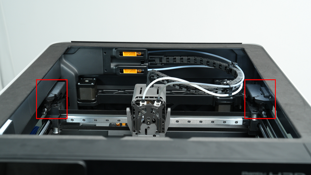
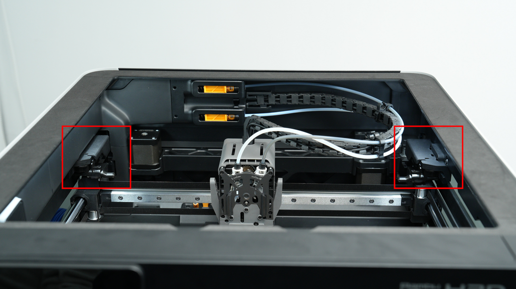
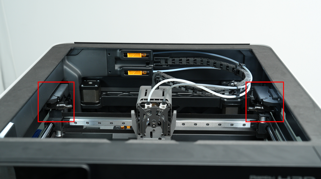
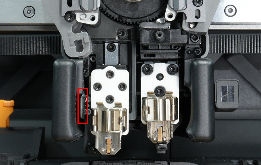
¶ Filament Cutter Stopper
To ensure the normal operation of the left and right cutters, there is a foldable cutter stopper on each side of the H2D.
During the operation of the printer, the cutter stopper rod has 3 possible states: zero position, working position, and toolhead homing avoidance position.
-
Zero position: Most of the time, the cutter stopper rod is in zero position, which does not affect any printing area.
-
Working position: When the cutter needs to cut filament, the stopper rod will move to the working position.
-
Toolhead homing avoidance position: To avoid affecting the accuracy of the Y-axis motor homing, the cutter push rod is in the avoidance position when the toolhead homes.
It should be noted that, unlike the X1 and P1 printers, the H2D’s cutter stopper rod does not limit the toolhead’s movement range, and the X-axis and Y-axis extreme printing ranges can be achieved without any special operations.
¶ Hotend
The hotend assembly is the toolhead module's core component, consisting of a hotend heating assembly, a hotend (with nozzle, heat blocker, and heat sink), and a hotend silicone sock. The maximum supported heating temperature is 350°C. The hotend assembly heats the filament to a specified temperature, and the melted filament is deposited in the form of a thin layer to generate a model.
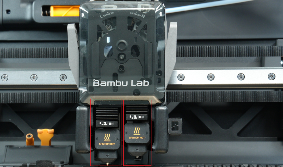
Different filaments often require different heating temperatures. For example, PLA materials are printed at lower temperatures around 210-220°C, while PPA materials need to be printed at higher temperatures around 300~320°C. Like the A1 series, the Bambu Lab H2D printer fixes the hotend heater and NTC temperature sensor to the heating base without unplugging and plugging tiny terminals or using a screwdriver. The hotend is fixed with a quick-lock buckle to ensure heat conduction and melting of the filaments. At the same time, based on the A1 hotend, the H2D design enhances flow by increasing the heating power and melt zone. In terms of material, it incorporates a zirconia ceramic insulating base and a copper heat-conducting base to improve insulation performance.
¶ The principle and function of the left hotend rising and falling
When the lifting motor rotates, the transmission mechanism drives the left hotend to rise and fall, and at the same time drives the flow blocker to swing left and right. There is a linkage relationship between the left hotend and the flow blocker. When the left hotend descends, the flow blocker will move to the right hotend to block the right nozzle; when the left hotend rises, the flow blocker will move to the left hotend to block the left nozzle, thereby preventing the hotend from leaking when not printing.
Note:
-
The function of the flow blocker is to block the non-working nozzle to prevent leakage. If there is a slight slight left-right tilt, it can be used normally as long as it does not affect the block function. If you find that the flow blocker does not press the nozzle, you can move the flow blocker connecting rod to the position between the two nozzles, try to manually bend the flow blocker upwards, and then manually switch the left and right nozzles on the screen to confirm that the flow blocker can block the nozzle normally and can move normally.
-
The flow blocker is located below the nozzle and is relatively fragile. In abnormal printing, the flow blocker may be deformed by abnormal protrusions. In this case, it is recommended to replace the flow blocker. The wind blocker is a thin steel sheet. When disassembling the hotend silicone sock or hotend, the wind blocker may be deformed. If the deformation is not serious, you can straighten it manually. If it is seriously deformed, it is recommended to replace the wind blocker.
At the same time, a wind blocker is installed next to the left hotend, which rises and falls with the left hotend, so that the wind blowing out of the air duct is concentrated on the heat sink of the hotend as much as possible, improving the heat dissipation efficiency and reducing the risk of blockage.

¶ Recommendations for materials used for the left and right hotends
-
If you only print monochrome materials, it is recommended to use the right hotend for printing.
-
If you need to work with AMS for multi-color printing, it is recommended to connect AMS to the right hotend.
-
If you want to use the second hotend to print support materials, it is recommended to use the lifting hotend for printing.
-
TPU is only suitable for the right hotend.
¶ Purge Wiper
The purge wiper of H2D includes a purge wiper part and a nozzle wiper part (rough wiping), wherein the purge wiper part is composed of a pushing plate and a receiving plate, and the nozzle wiper part is composed of a pushing rod and a wiping nozzle connecting rod.
-
Purge wiper part: It's used to efficiently handle the waste filaments ejected from the nozzle. Its functions include collecting and transporting waste filaments to ensure that the waste is properly disposed of to ensure a smooth and continuous printing process. The device plays an important role in multiple printing processes, including printer preparation, pausing and resuming printing, loading and unloading filaments, and the swapping of the filament and flushing process during multi-color printing.
-
Nozzle wiper part: It's used to clean the nozzle before starting a print task. Each time a print task is started, the cleaning action is performed automatically without manual intervention. It should be noted that replacing the silicone nozzle wiper is part of the regular maintenance procedure. If the silicone nozzle wiper is damaged, you can purchase a replacement part in the official store.
Cleaning the nozzle before printing includes rough wiping and fine wiping. Rough wiping is mainly used to remove residual waste from the nozzle, while fine wiping ensures the smoothness of the nozzle surface. The nozzle wiper part mentioned here is used for rough wiping, and fine wiping means that the nozzle is rubbed down 1~2 mm at nozzle wiper steel sheet of the hotbed to achieve a better cleaning effect.
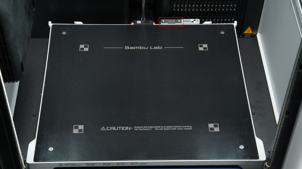
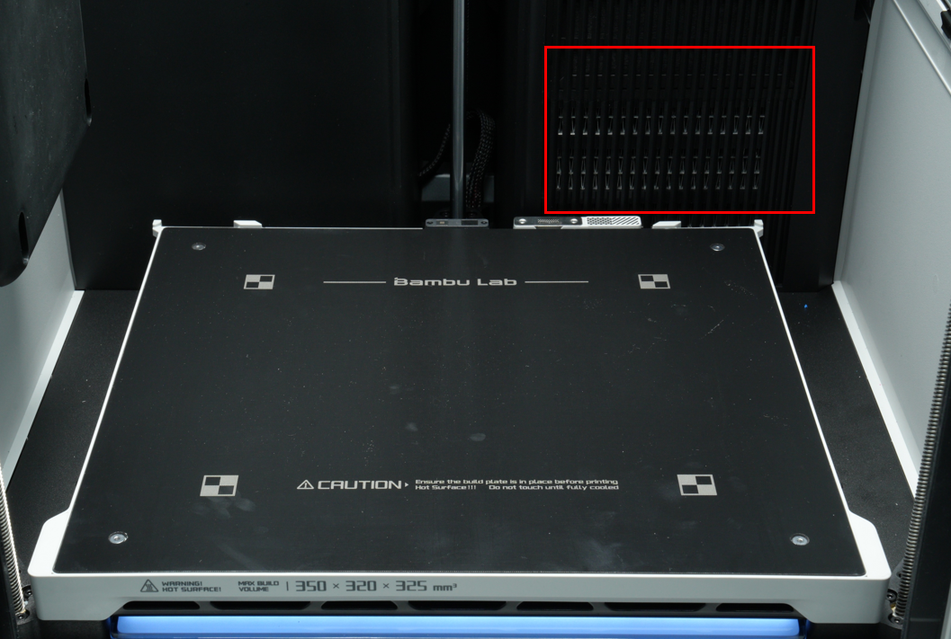
¶ Heatbed
The heatbed is used to heat the printing surface to help the printed layers adhere better to the build plate. If the printing surface is not heated, the deposited filament will cool quickly and the tension between the layers will cause it to warp. During the printing process, the H2D printer will adjust the heating temperature of the heatbed according to the type of material used, up to 120°C. For example, when using PLA material, setting the heatbed temperature to 35-45°C when printing on a Bambu Cool Plate can effectively avoid warping. For materials such as ABS and PC, to prevent warping, the heatbed temperature needs to be set between 100-110°C for printing.
The maximum printing area of the heatbed surface is 350 x 320 mm². (The actual printing area depends on the nozzle used; for more details, refer to Introduction to the printable range of H2D dual nozzles
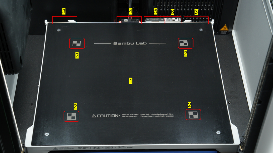
The heatbed of the H2D printer consists of the following parts:
| Module name | 1 Heating area | 2 Marker on the magnet surface | 3 Build plate positioning parallel block | 4 Nozzle offset calibration coil |
|---|---|---|---|---|
| Function | Heating surface | Calibrate the BirdsEye camera and live camera | Easy to place the build plate accurately | Used to calibrate the left and right hotend offsets to ensure that the positioning of the two hotends is exactly the same. |
| Note | Avoid scratching the soft magnetic sticker with sharp objects. | Avoid scratching the soft magnetic sticker with sharp objects. | When placing the build plate, you can tilt it slightly and slide it inwards, and put it down when it reaches the limit position. | If you find that the model has an obvious layer shift after switching the nozzle during printing, it is recommended to perform a nozzle offset calibration. |
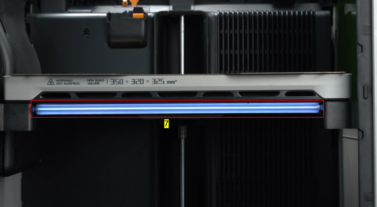
| Module name | 5 Nozzle wiper steel sheet | 6 Calibration sticker | 7 Status Indicator |
|---|---|---|---|
| Function | Clean the nozzle and ensure the nozzle face remains smooth | For calibrating the toolhead camera | Used to indicate the printer's health status and printing task status. |
| Note | It can be removed and replaced after severe wear. | Avoid scratching the sticker with sharp objects. |
¶ Build Plate
The H2D series printer comes with a Textured PEI Plate.
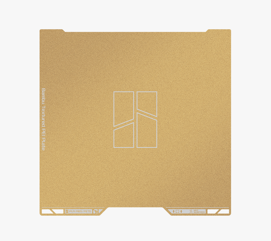
Please check the Introduction to the Build Plates Wiki for more information about our build plates.
¶ Cooling System and Heating System
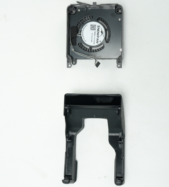
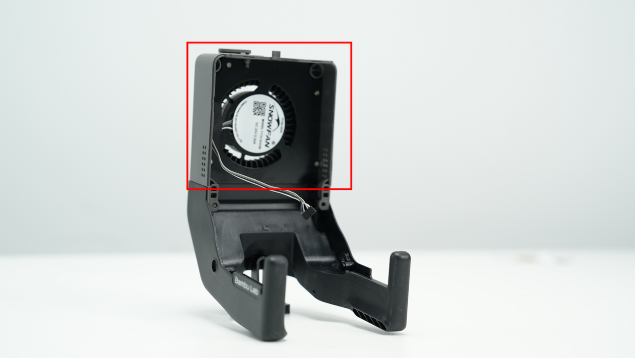
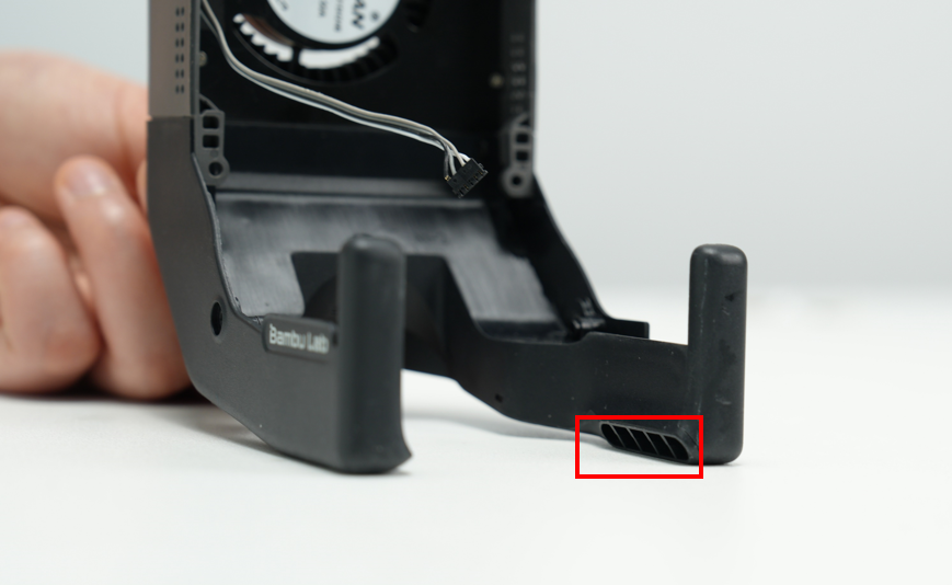
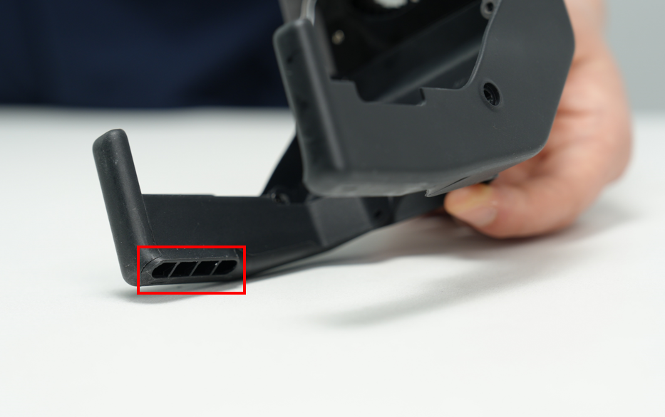
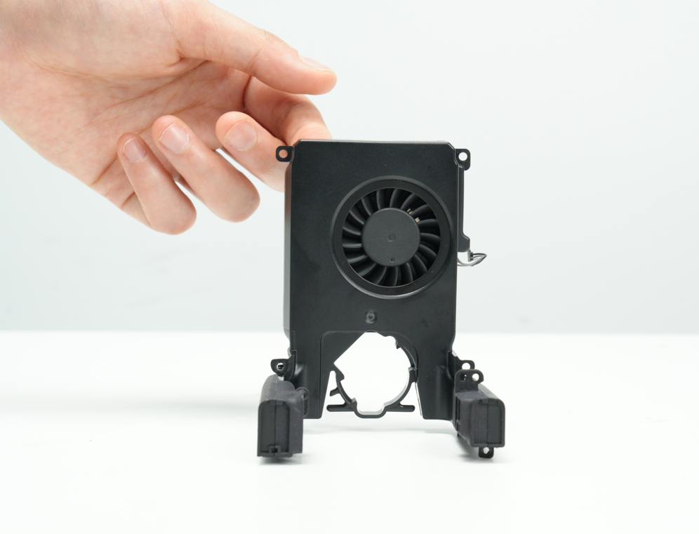
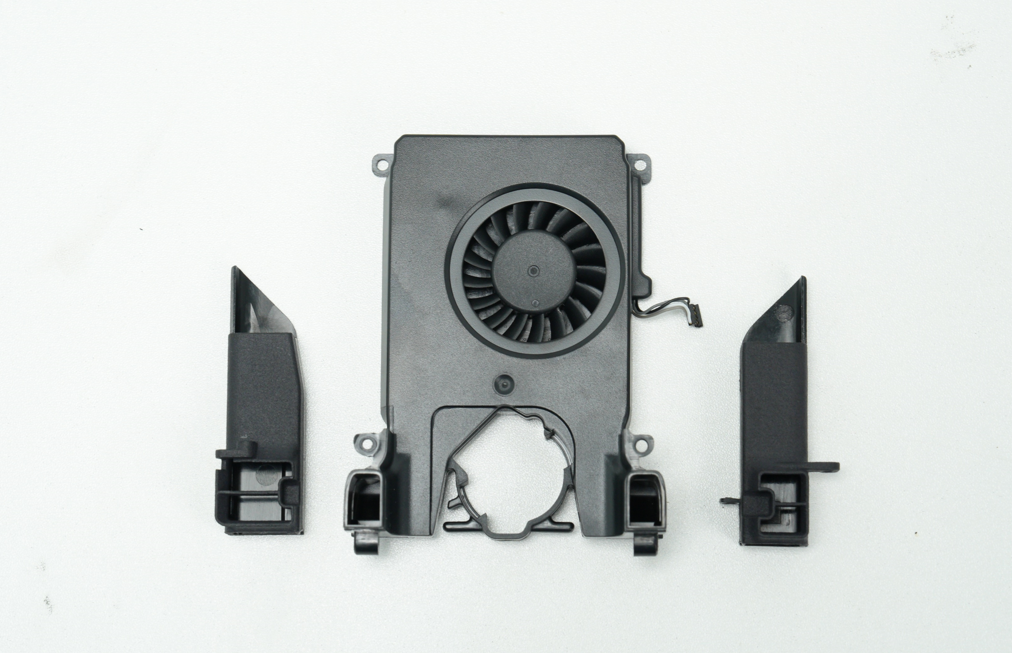
¶ Part cooling fan and air duct
Fast printing requires good cooling of the printed parts. H2D is equipped with a customized 5015 centrifugal fan and air duct. The cooling air blown out by the fan will be blown to the vicinity of the left and right hotends through the air duct, thereby ensuring fast cooling of the printed parts on the left and right hotends.
¶ Cooling fan for hotend and air duct
H2D is equipped with a cooling fan for hotend and air duct. The cooling air blown by the fan is directed to the heat sinks of the left and right hotends through the air duct to keep the hotend temperature stable and prevent overheating, thereby improving print quality and reducing clogging problems. In addition, the left hotend is also equipped with a wind blocker. For specific details about the wind blocker, please refer to the principle and function of the left hotend rising and falling.
¶ Auxiliary part cooling fan
H2D is equipped with an additional cooling fan on the left side of the chamber. For some filaments (such as PLA), good heat dissipation helps improve printing results. Turning on the fan will form an "airflow layer" on the print, which helps to cure the print layer as quickly as possible.
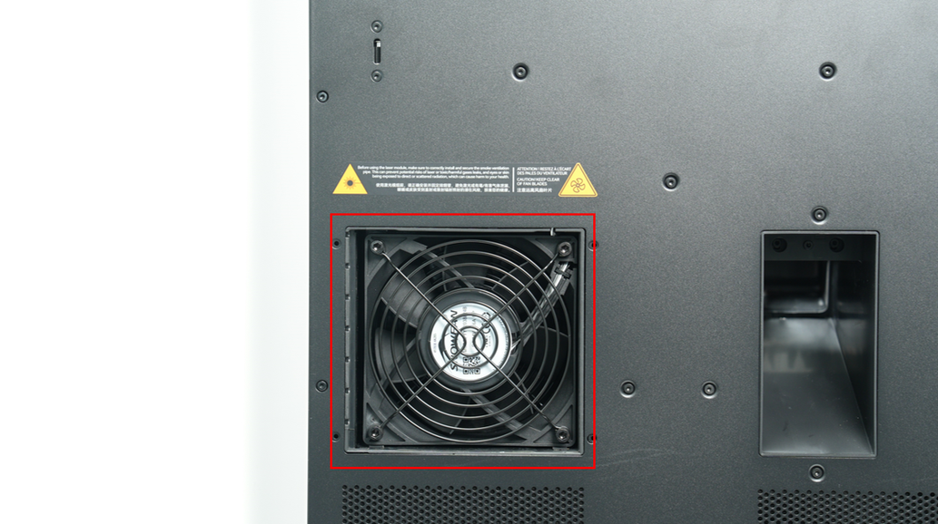
¶ Chamber cooling system
When the printer starts the external exhaust fan, the automatic top vent and the active chamber exhaust on the back of the printer will automatically open to accurately control the chamber temperature or control the airflow in the chamber. The automatic top vent acts as an air inlet and cooperates with the active chamber exhaust at the air outlet to provide sufficient air intake for the system while ensuring that the airflow in the chamber is as expected and controllable.
When the printer is idle or during printing, if the chamber temperature heating is not activated, the printer is in cooling mode.
In cooling mode:
-
The filter switch flap remains open;
-
The active chamber exhaust and automatic top vent will open along with the chamber exhaust fan to ensure air circulation between the printer chamber and the outside world and reduce the temperature inside the cavity.
In order to balance the noise and cooling effect, the speed of the chamber exhaust fan will increase as the chamber temperature rises during printing. When the chamber temperature of the printer is low and the cooling demand is not strong, the chamber exhaust fan will reduce its speed to 30%.

In summary, the automatic top vent and active chamber exhaust have the following two main functions:
-
During 3D printing, the system will automatically control the opening and closing and ventilation according to the type of filaments being printed and the detection of the chamber temperature to achieve precise control of the chamber temperature;
-
When the laser module is working, sufficient air intake should be provided to help the exhaust gas and particles generated by the laser operation to be fully filtered by the filter element before being discharged outside the machine to reduce pollution. At the same time, the opening angle of the vent has been carefully designed to ensure sufficient air intake and avoid direct laser exposure to the outside of the equipment, thereby reducing potential harm to the human body.
¶ Chamber heating system
When the chamber is heated, the printer's circulation system switches to heating mode, and the active chamber exhaust and the automatic top vent are closed. To increase airflow and speed up the temperature rise during the chamber temperature rise stage, the filter switch flap is opened; while in the chamber temperature maintenance stage, the filter switch flap is closed to ensure the filtering effect.
When the chamber temperature is set on the screen, or heating mode is selected, or chamber temperature heating is configured in the slicing file, the printer enters heating mode (but the chamber heater may not necessarily be in a heating state).
The chamber temperature is set on the screen, Bambu Studio or Bambu Handy, the printer will automatically switch to heating mode and the chamber heater will start working.
The chamber heater consists of a PTC heating plate and a chamber heat circulation fan. After the chamber temperature is set, the PTC will heat at full power and the chamber heat fan will run at maximum speed. When the chamber temperature reaches the set value, the speed of the chamber heat fan remains unchanged, and the power of the PTC will decrease to maintain the chamber temperature at a constant value.
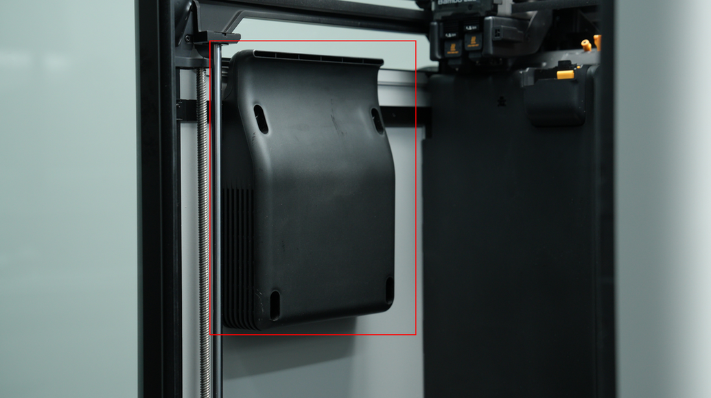
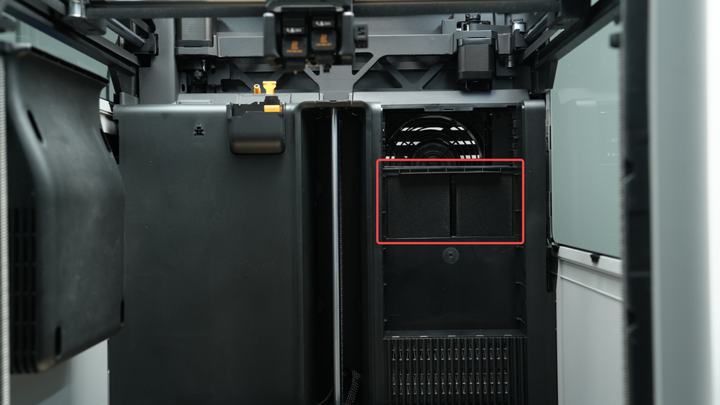
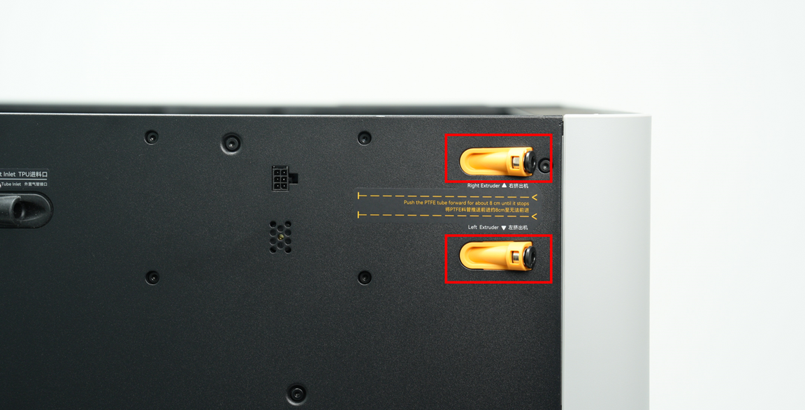
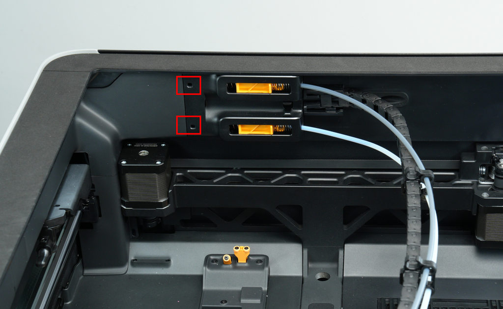
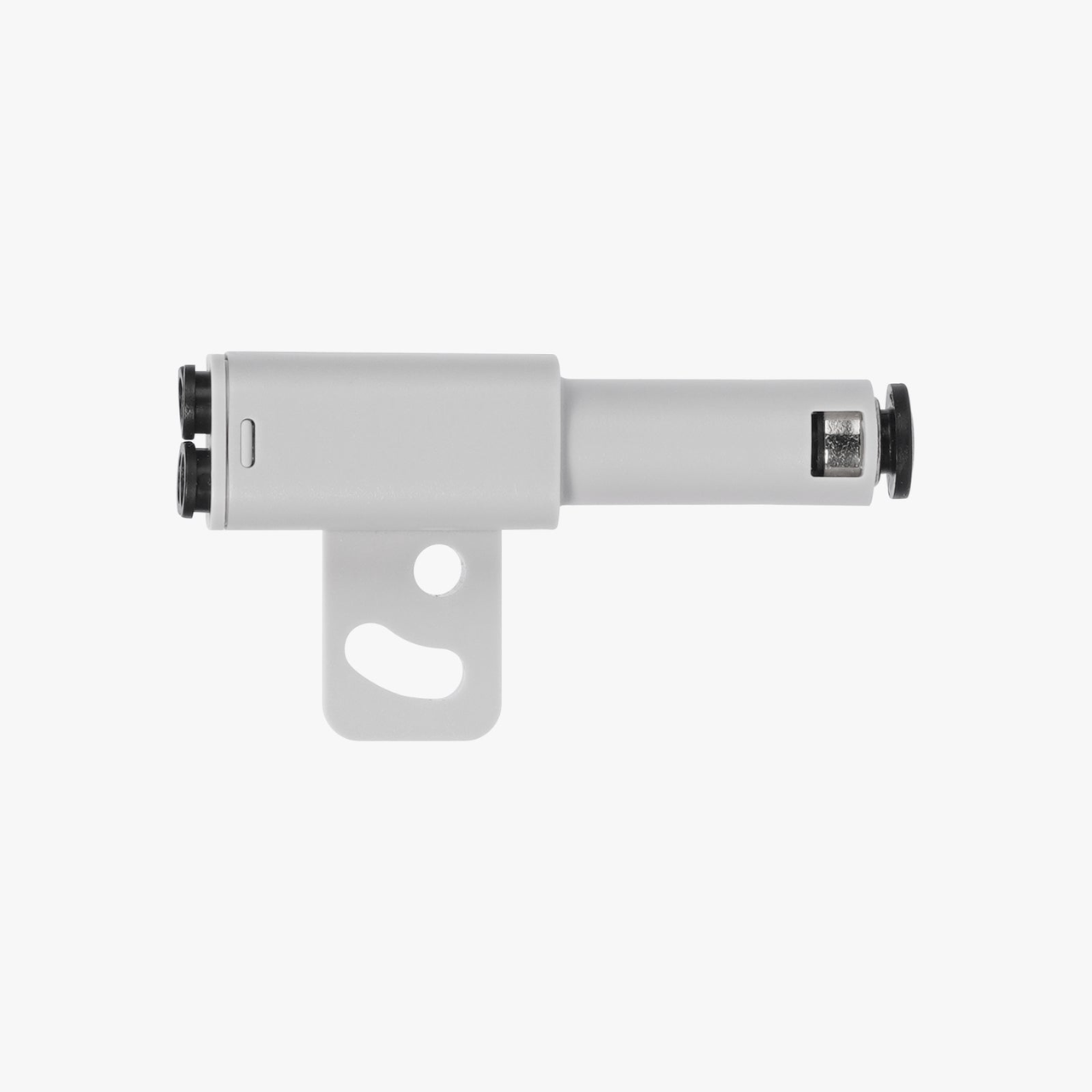
¶ Filament Buffer
It has two filament channels, corresponding to the two hotends respectively. The upper channel of the buffer is connected to the right hotend, and the lower channel is connected to the left hotend. Combined with the standard length tube that comes standard with the factory, the resistance during the feeding process can be reduced as much as possible.
When using the buffer, you need to first insert the PTFE tube from the tube bracket at the back of the printer. Note that it must be inserted all the way to the bottom and cannot be inserted deeper. You can see that the PTFE tube is in place from the opening on the front of the buffer. During the process, a guide track is designed on the AP plate cover to ensure that the tube can be smoothly inserted into place. It should be noted that the track on the AP plate cover can only pass the PTFE tube to guide the filaments into the buffer. If the PTFE tube is not inserted and the filaments are directly inserted, it is almost impossible to successfully send the filaments into the buffer.
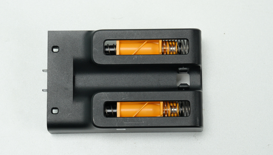
Each channel is divided into a buffer part and a filament detection part. The buffer part mainly includes a slider, a magnet, two springs, and a Hall sensor; the filament detection part mainly includes a magnet, a spring, and a Hall sensor.
¶ Buffer part
The basic working principle of the buffer part is that when the AMS pushes the filament into the toolhead extruder, the pressure of the filament pushes the slider to the right and stores a small section of the filament in the buffer. When the extruder consumes the filament in the buffer, the slider returns to the left. The position of the slider is detected by the sensor and fed back to the AMS and the printer to adjust the feeding speed.
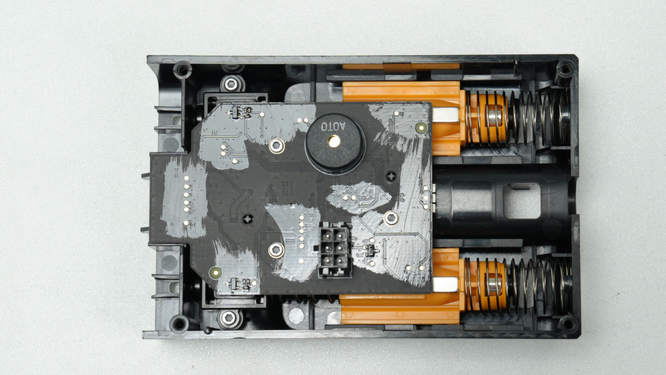
In addition, when printing with an external spool, the buffer part also has a material entanglement detection function, which can detect whether the external spool is entangled. Unlike the buffer of the X1/P1 series, the H2D has a filament tangle spring on the other side of the buffer spring. When the filament enters the printer, the resistance increases (for example, when the filament is entangled), and the toolhead is still extruding, the slider moves to the left. After moving a certain distance, the return value of the Hall sensor exceeds the threshold, and it will be judged that the filament is entangled. The printer will pop up an HMS prompt to inform the user to handle it, realizing the filament tangle detection function.
¶ Filament detection part
The H2D features a filament detection function at the buffer. When used with the official tube expansion port, it enables a single hotend to work with up to four AMS units, eliminating the AMS Hub required for X1/P1.
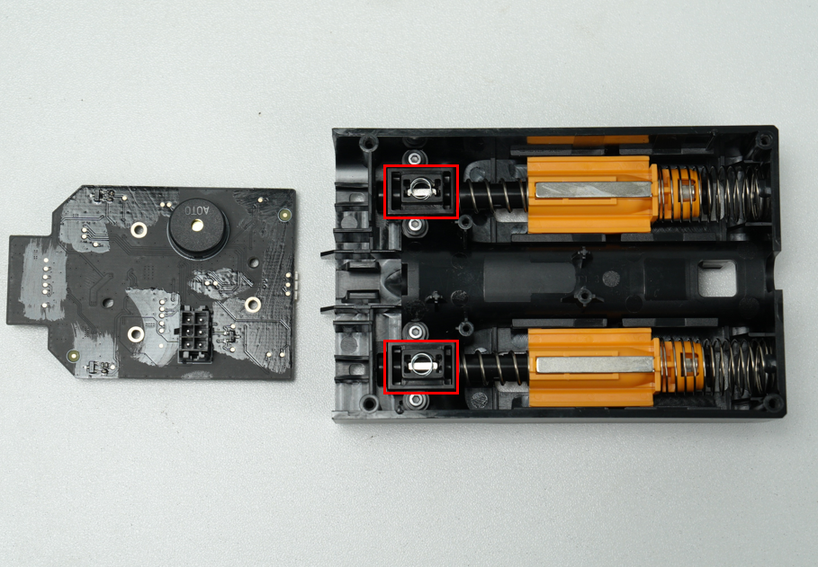
There is a magnet in the filament detection part. When there is no filament, the magnet is pressed by the spring to a position away from the Hall sensor. When there is filament, the magnet is lifted by the filament and close to the Hall sensor, realizing the function of filament detection.
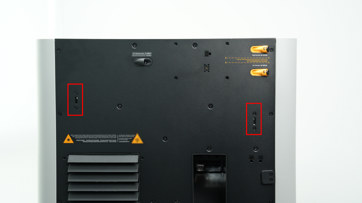
¶ Belt tensioner
The H2D has an adjustable belt tensioner on the rear. The Belt Tension Monitor (BTM) will monitor the tension of the belt and provide feedback to you to adjust the belt tension for optimum performance.
¶ Electrical Components
There are many electronic components inside the H2D. Here is an introduction to some of the most important ones:
¶ Main control board
H2D has two types of core main control boards, one is responsible for interactive logic processing, and the other is responsible for the control processing of the whole machine motion unit.
¶ AP Logic mainboard
The logic mainboard contains a quad-core CPU and the connections required for the different media electronics connected to the printer.
The CPU handles the H2D's intelligent functions (including AI detection, flow calibration, and vibration compensation) and the connection between the slicing software/mobile app and the printer.
¶ MC motion control board
The motion control board contains a dual M4 core MCU, a single M7 core MCU, and stepper drivers and connections to the different motion electronics of the printer, providing: xyz motion control, chamber temperature control, heatbed temperature control, chamber status detection (door, top cover, side panel switch and glass type detection), and circulation system control (air circulation and flow channel control)
The MCU controls the actual movement and overall status of the printer after obtaining the G code stream from the CPU.
¶ USB storage interface
H2D has a common USBA interface that supports USB2.0 protocol, which can be used to initiate offline printing and storage of timelapse video files from a USB flash drive.
¶ Screen
The H2D is equipped with a 5-inch 1280*720 touchscreen, combined with a smoother user interface to provide a seamless operating experience.
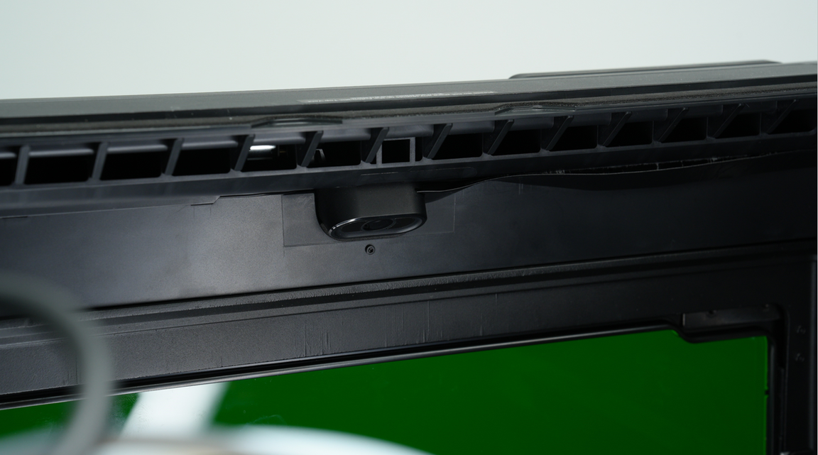
¶ Nozzle camera
The H2D features a nozzle camera that supports 1080p 10fps (up to 30fps), which can detect hotend clumping, air printing, spaghetti detection, and trash can position calibration.
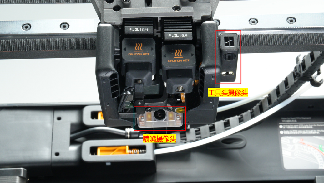
¶ Toolhead camera
The H2D features a toolhead camera that supports 1080p 30fps and can be used for motion accuracy calibration, high-precision nozzle offset calibration, build plate and laser platform identification code recognition.
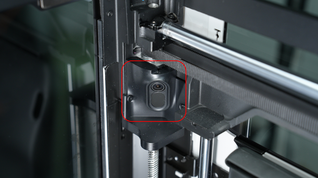
¶ Live camera
The H2D features a live camera that supports 1080p 30fps, which enables live viewing inside the printer chamber, timelapse, and necessary AI detection functions.
¶ BirdsEye camera (optional in the printing module, and necessary in the laser)
The H2D can be optionally equipped with a 4K, maximum 15fps BirdsEye camera to meet the intelligent detection and recognition functions in the laser & cutting extended scenarios.
¶ LED light
The left and right beams of the H2D are each equipped with an LED light bar to ensure adequate lighting in the chamber.
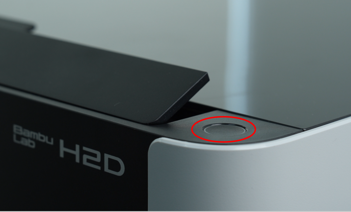
¶ Start/Pause button
Laser tasks require supervision. Therefore, after sending a laser work task or die-cutting task in the preprocessing software, the operator needs to press the start button located at the top right of the printer to begin the task.
The start button also supports pause functions for laser module tasks, cutting module tasks, and 3D printing (the pause function for 3D printing requires a firmware update, which is expected to be available by the end of August 2025).
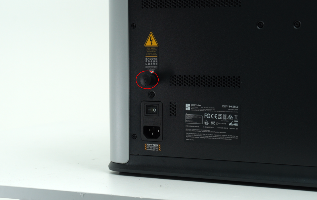
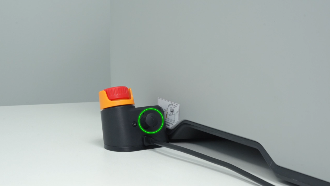
¶ Safety key
To ensure compliance with relevant safety regulations, the H2D printer is equipped with a safety key jack, which must be inserted with a safety key(printing and cutting module) or an emergency stop button with a safety key(laser module) to enable power. If the printer does not power up properly after connecting the printer power supply and turning on the power switch, be sure to check this.
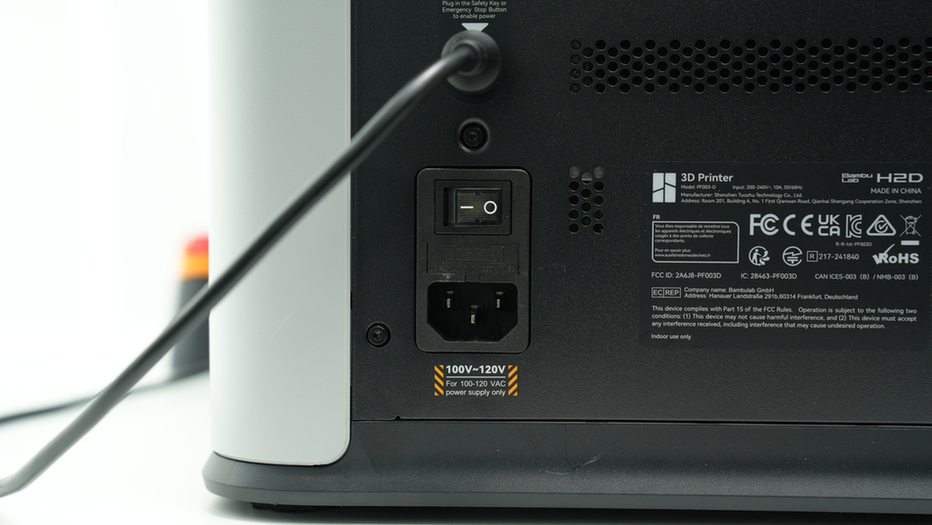
¶ Emergency stop button (optional in the printing and cutting module, and necessary in the laser module)
If you need to use the laser function, you must install an emergency stop button with a safety key and insert the plug of the emergency stop button into the safety key slot on the back of the printer.
Someone needs to supervise the laser task throughout the process and press the emergency stop button in time to cut off the power supply in an emergency to prepare for potential emergencies at any time.
Tips: There is a pre-installed safety key on the back of the printer and the emergency stop button. Please keep it properly after removing the safety key on the back of the printer.
¶ End Notes
We hope the detailed guide provided has been helpful and informative.
If this guide does not solve your problem, please submit a technical ticket, we will answer your questions and provide assistance.
If you have any suggestions or feedback on this Wiki, please leave a message in the comment area. Thank you for your support and attention!