¶ 1. How to Use the Image Capture Function
¶ Starting Image Capture and Real-Time Positioning
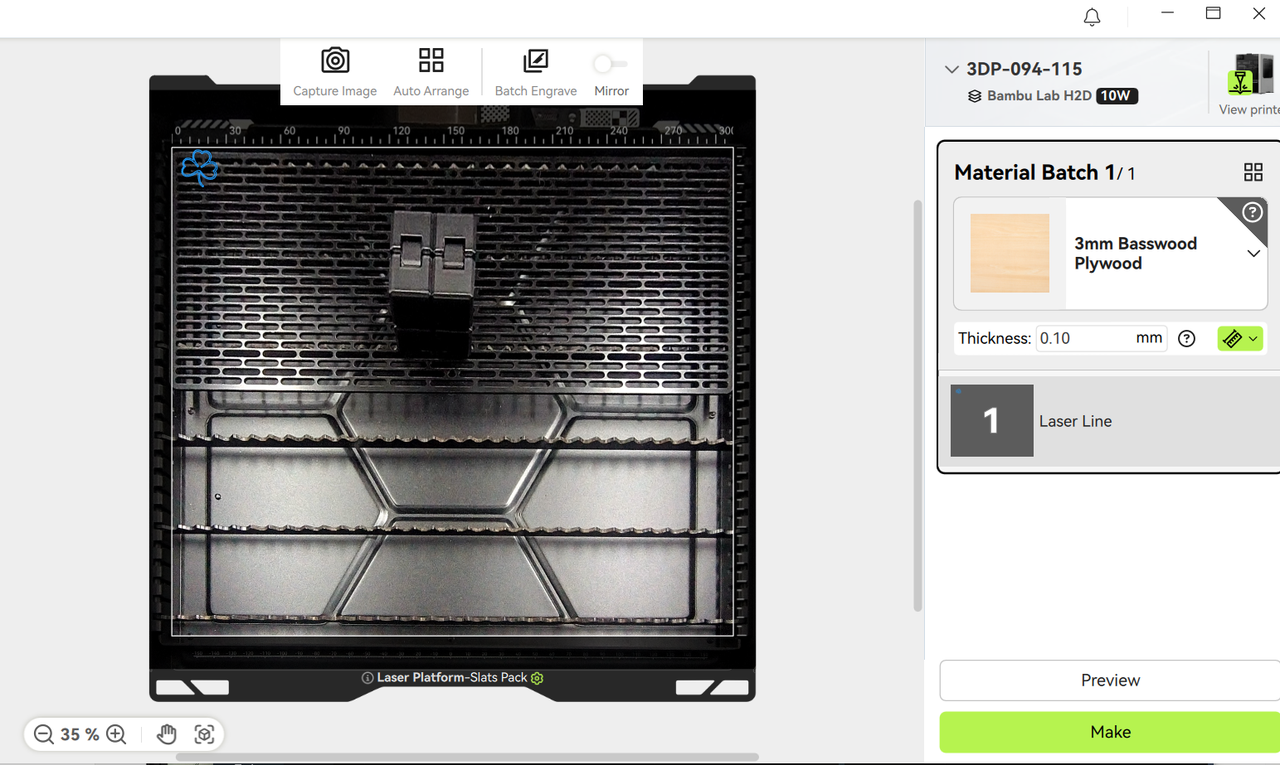
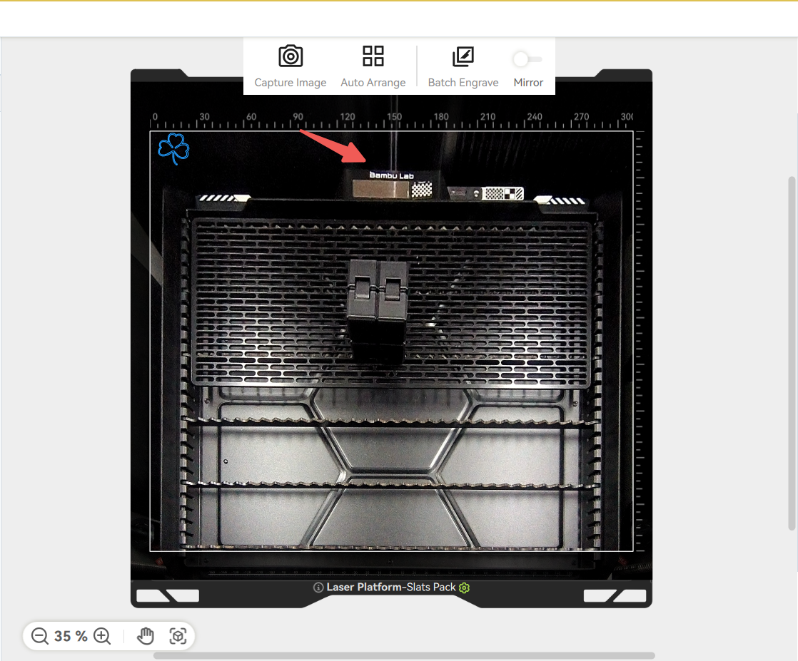
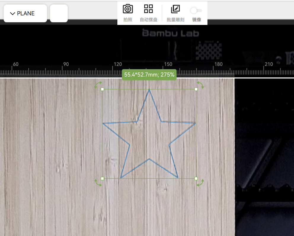
Go to the Bambu Suite "Preparation" page → Click the "Capture Image" button in the top toolbar → The printer automatically takes a bird's-eye view of the platform. Once the image is displayed, drag and drop patterns to their actual processing positions for "What You See Is What You Get" (WYSIWYG) alignment.
If you need a finer material outline, you need to manually turn on the Fine Contour Extraction switch. By default, the fine outline is turned off, which means that the default automatic plate placement uses a relatively rough outline. In most cases, using the fine outline will get a more accurate material outline boundary, but the outline extraction process will be more time-consuming.
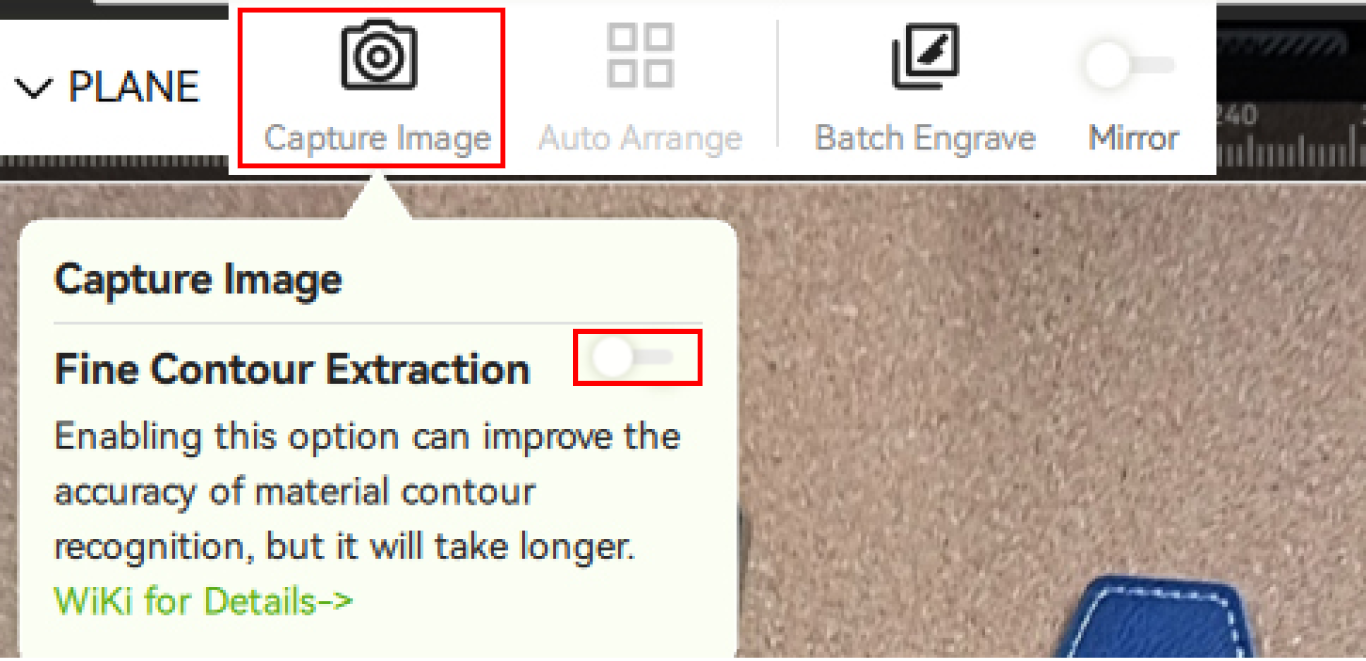
- Move the mouse over the Capture Image button, and turn on fine contour extraction in the floating window.
- It is recommended to enable this option to increase the success rate when objects area placed tightly or when objects are relatively thin or tiny.
- Enabling fine contour extraction will improve the accuracy of contour processing, while also increasing the calculation time of contours. Batch Engrave and Auto Arrange will wait for the completion of fine contour calculation.
- When starting fine contour extraction for the first time, the "Fine Contour Extraction AI Model" will be downloaded online. After downloading, the fine contour of the target object can be processed when taking photos.

¶ Smart Material Change Detection
If you open the front door to reposition or replace materials, the software will notify you to click "Refresh" or recapture the image to update the view. If using Bambu official materials, the photo capture process can also automatically identify the material inside the chamber and sync it to the material group, as shown below.
¶ Clearing the Captured Image
Right-click anywhere on the page → Select "Clear Captured Image" → Restore the default background.
¶ 2. How to Obtain Accurate Alignment Images
Working Principle
Due to the installation position of the bird's-eye view camera, its perspective is taken at an angle, which can distort the perspective of the image. Therefore, the material thickness needs to be used to calibrate and correct the perspective deviation. As shown in the GIF below, changing the preset material thickness adjusts the top-down view accordingly.
Bird's-eye camera:
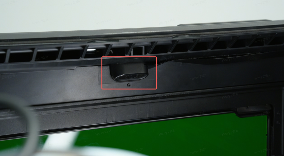 Bird's-eye camera Bird's-eye camera |
 |
Correct Procedure
-
Ensure the preset material thickness closely matches the actual thickness. Select or input a preset value close to the real thickness of the object.
-
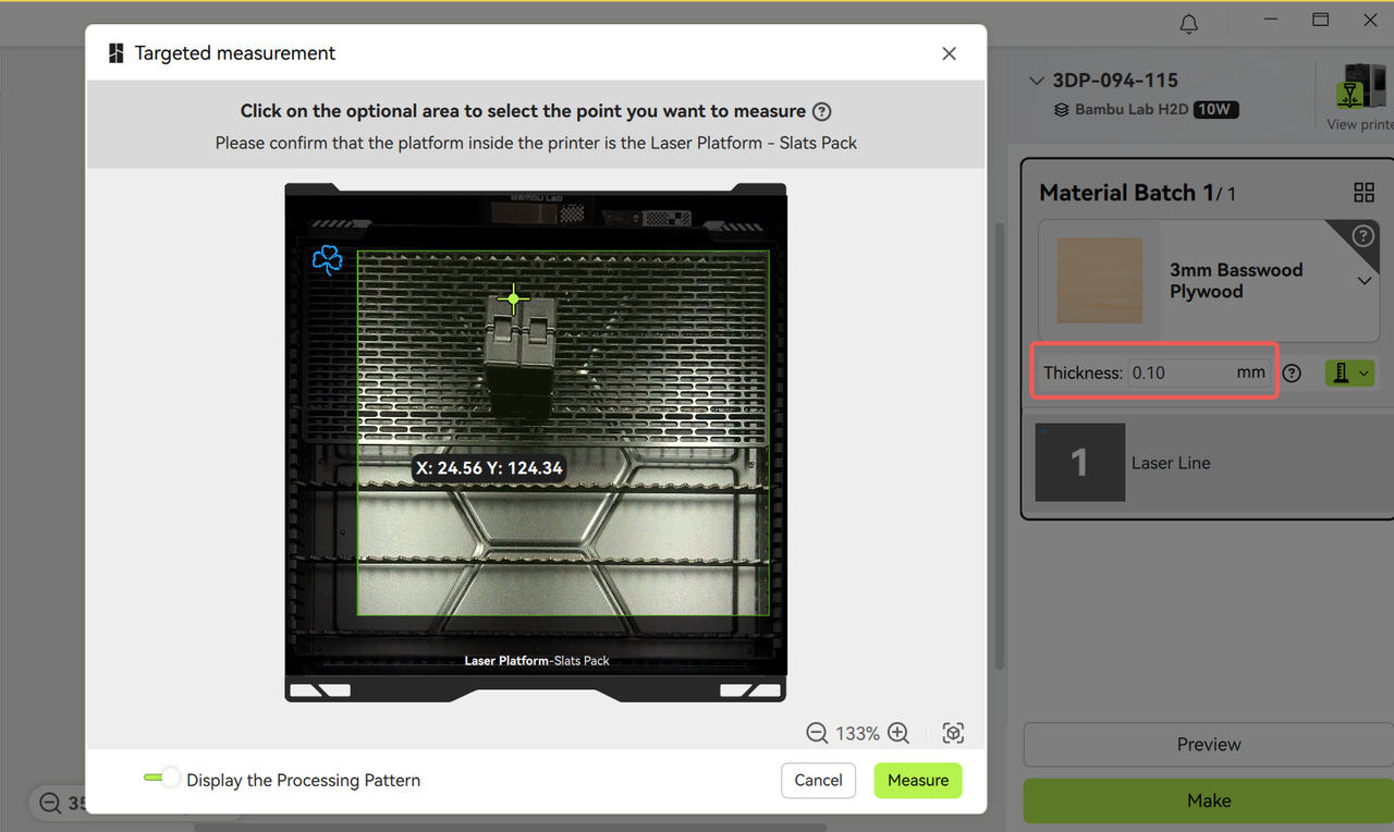
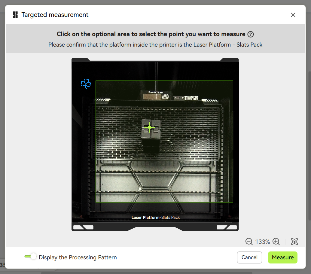
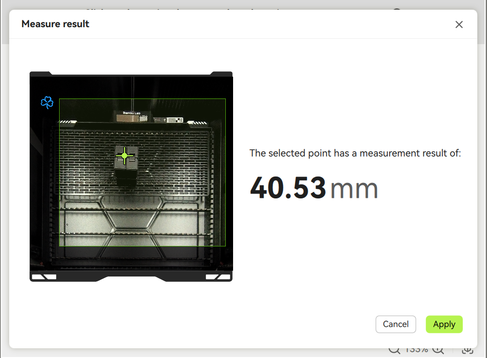
Use the software’s auto-thickness measurement tool for precise calibration. The Bambu Suite thickness measurement tool includes the targeted thickness measurement feature: Select the desired processing area on the image to measure its exact thickness. Since the material's surface is usually uneven, measuring the thickness in the processing area can help the camera obtain a more accurate image of the processing plane (Note: Only works for flat surfaces; avoid irregular shapes).
Material thickness measurement
¶ 3. Common Issues & Solutions for Thickness Measurement
Problem Description
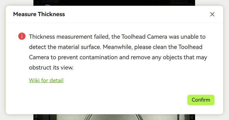
As mentioned earlier, if the preset material thickness significantly deviates from reality, the actual object position may not align with the image, making surface detection difficult (especially for objects >30mm thick, which may risk toolhead collisions).
As shown below, incorrect thickness settings can cause measurement points to miss the actual surface, leading to inaccurate or failed readings.
Solutions
- Manually input an approximate thickness → Wait for the image to refresh.
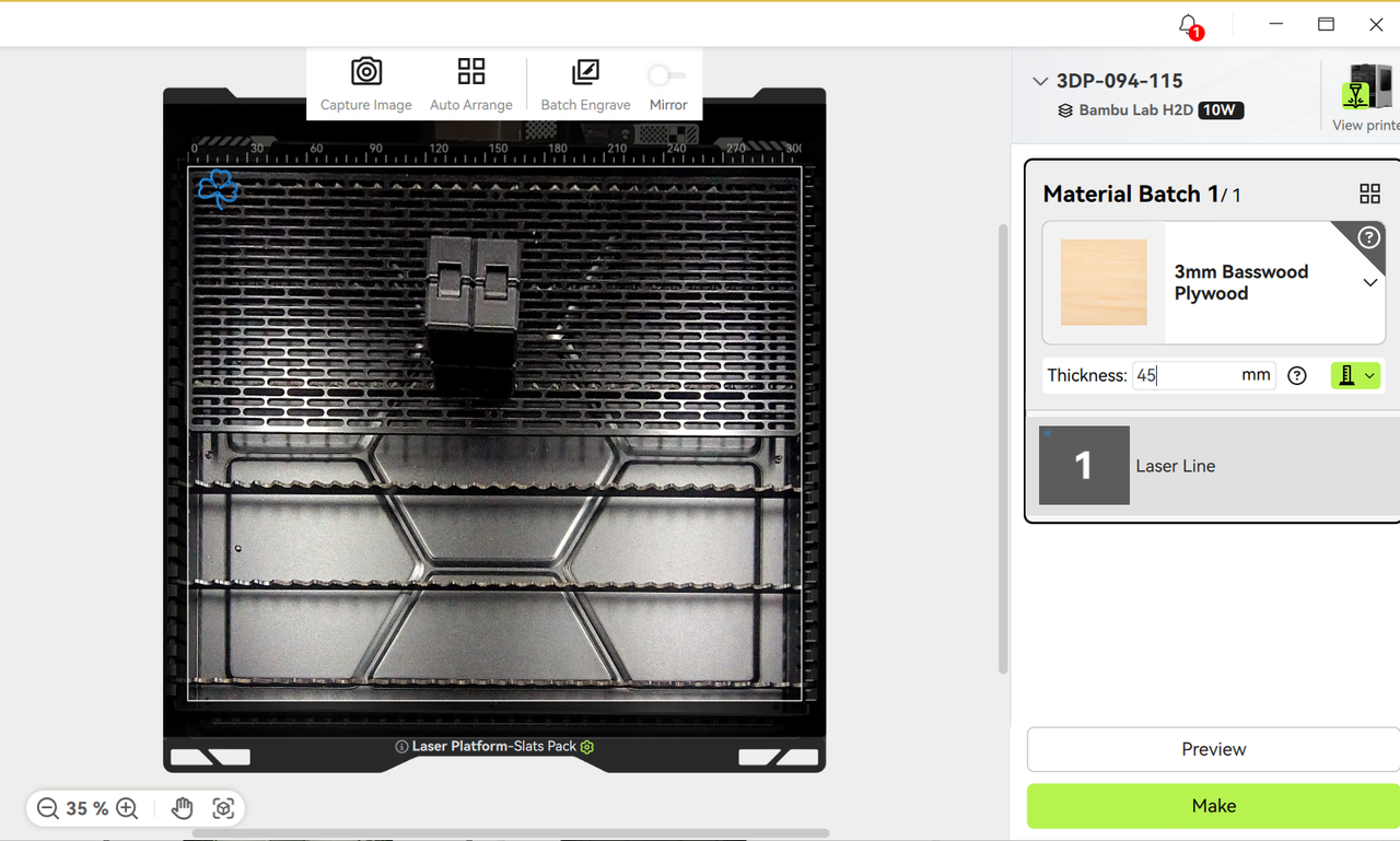
- Re-measure with point selection → Apply the precise thickness value before starting the job.
Special Case: For thick objects, background distortion in the image is normal—this ensures accurate positioning of the processing surface.
¶ 4. Solution to Camera Alignment Error
Under normal conditions, the deviation between the engraved position and the preview should not exceed 0.3mm. You can capture the image again after the processing is completed to judge the deviation between the actual engraving position and the position you designed.
If the deviation is large, please follow the following steps:
Step 1: Verify Thickness Accuracy
-
Check if the Auto-Measure thickness was used.
-
If relying on preset/manual inputs with large deviations, remeasure using the software’s tool or a caliper.
Material thickness measurement
Step 2: Recalibrate the Bird's-eye Camera
-
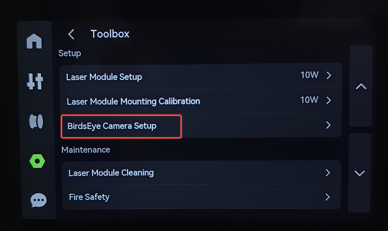
If the camera was manually adjusted or disassembled, its position may have shifted → Perform a Bird's-eye Camera Setup.
-
Over time, natural calibration drift may occur → Manually reinitialize the camera to correct errors.