¶ When to use
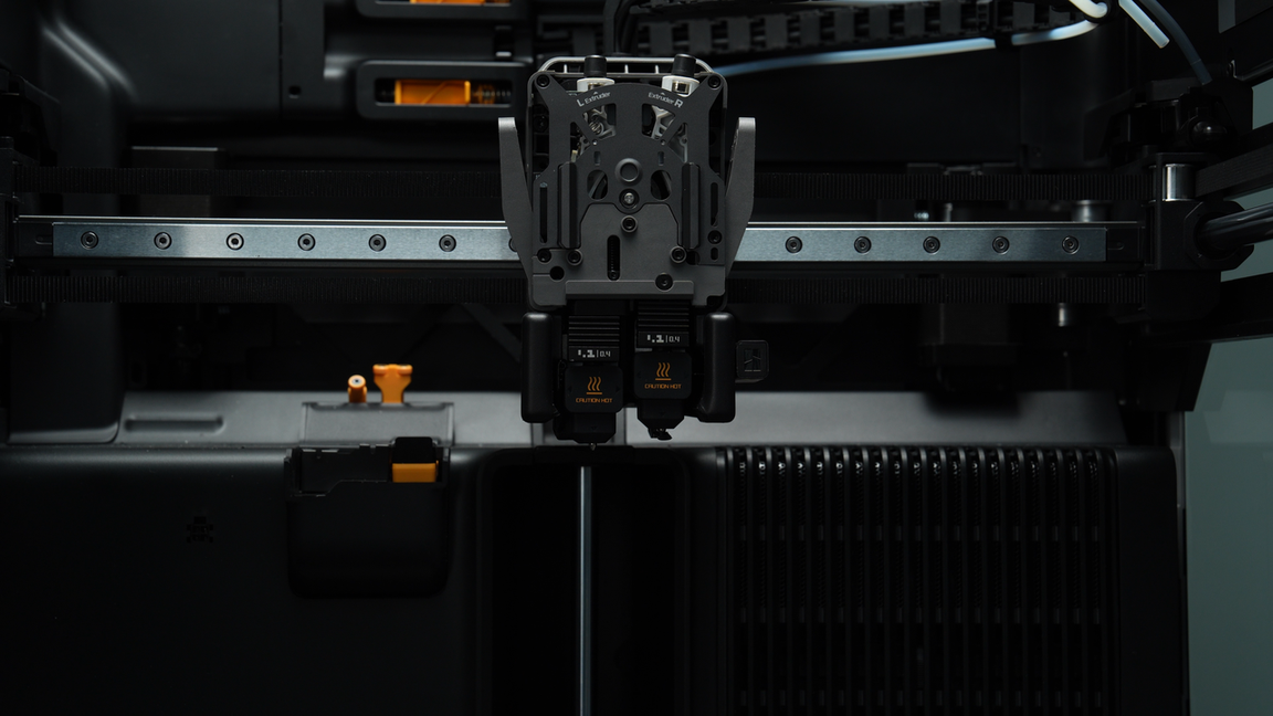
The extruder should undergo regular maintenance as its components play a crucial role in printing quality. Over time, accumulated filament debris, dust, and other particles inside the extruder may affect printing quality. When encountering the following situations, it is recommended to follow the steps in this guide:
-
Blockages are caused by filament deformation in the extruder gears, extruder filament guide, or dual extruder idlers due to excessive temperatures.
-
Printing quality issues such as inconsistent textures resulting from the gradual accumulation of filament debris or dust inside the extruder unit.
-
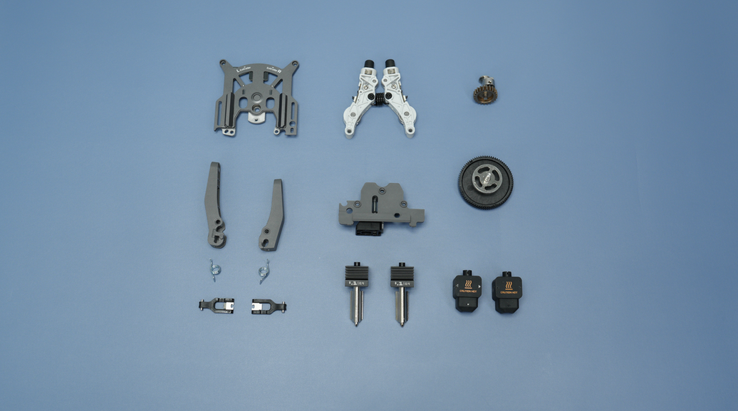
Replacement of internal parts of the extruder unit, such as the extruder front cover, extruder filament guide, dual extruder idlers, extruder switch cam, left and right cutters and handles, or extruder gears.
Here are additional instructions: for clogging issue, it is strongly recommended to first read this wiki article: How to check which part is clogged in H2D to confirm whether the clog is indeed caused by extruder unit, to avoid misdiagnosing the issue and unnecessary disassembly. You can start by removing the hotend and observing if the filament can be extruded properly. If the filament extrudes normally after the hotend is removed, it indicates a hotend clog rather than an extruder clog. Then you can resolve the issue by cleaning or replacing the nozzle.
The approach of this article is to clear the extruder using the fewest steps possible and these steps can also be referenced for disassembling and assembling the extruder.
-
If the blockage has been cleared after completing certain steps, you can skip ahead. For instance, cleaning filament debris or dust typically only requires disassembling the extruder filament guide. If a blockage occurs without severe filament jamming, you may only need to open the extruder front cover, without removing the extruder idlers. Please disassemble and assemble as needed.
-
When replacing the left and right cutter levers or the right cutter, you can skip removing the extruder filament guide and front cover. After removing the toolhead front cover, proceed directly with the replacement, ensuring to keep the torsion spring and cutter levers and install the cutting blade with the notch facing upwards.
-
For disassembling the extruder filament guide, it is highly recommended to refer to instructional videos as there is some interference between the extruder filament guide and the left and right cutter and levers, requiring skillful removal. If you find it challenging to follow the video instructions, you can first remove the cutter lever before disassembling the extruder filament guide.
¶ Tools and materials needed
This maintenance is expected to take between 10 and 60 minutes to complete, with the specific duration depending on the extent of disassembly.
- H1.5 & H2.0 Allen key
¶ Safety Warning
IMPORTANT!
It's crucial to power off the printer before performing any maintenance work on the printer and its electronics, including toolhead wires, because leaving the printer on while conducting such tasks can cause a short circuit, which can lead to additional electrical damage and safety hazards.
When you perform maintenance or troubleshooting on the printer, you may be required to disassemble some parts, including the hotend. This process can expose wires and electrical components that could potentially short circuit if they come into contact with each other or with other metal or electrical components while the printer is still on. This can damage the electronics of the printer and cause further damage.
Therefore, it's essential to power off the printer and disconnect it from the power source before doing any maintenance work. This will prevent any short circuits or damage to the printer's electronics. By doing so, you can avoid potential damage to the printer's electronic components and ensure that the maintenance work is performed safely and effectively.
If you have any concerns or questions about following this guide, open a new ticket in our Support Page and we will do our best to respond promptly and provide you with the assistance you need.
¶ Video Guide
¶ Disassembly Steps
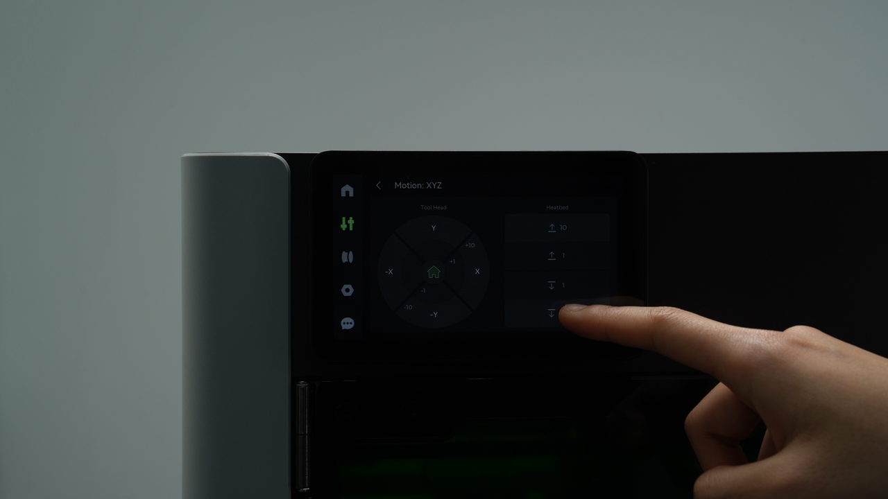
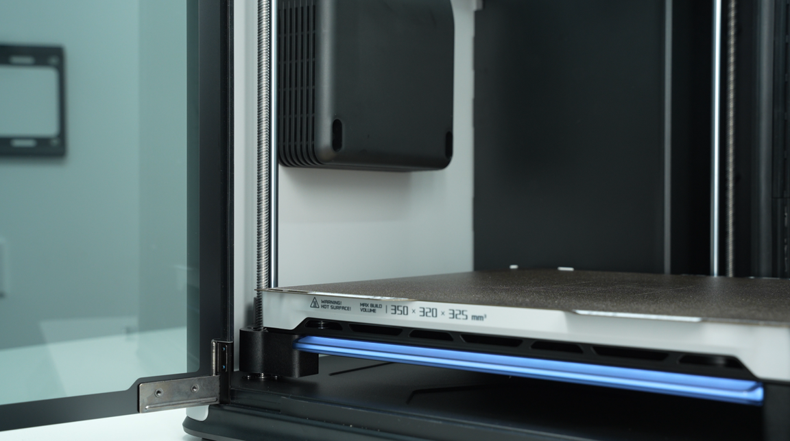
¶ Step 1: Lower the heatbed to create space for toolhead disassembly
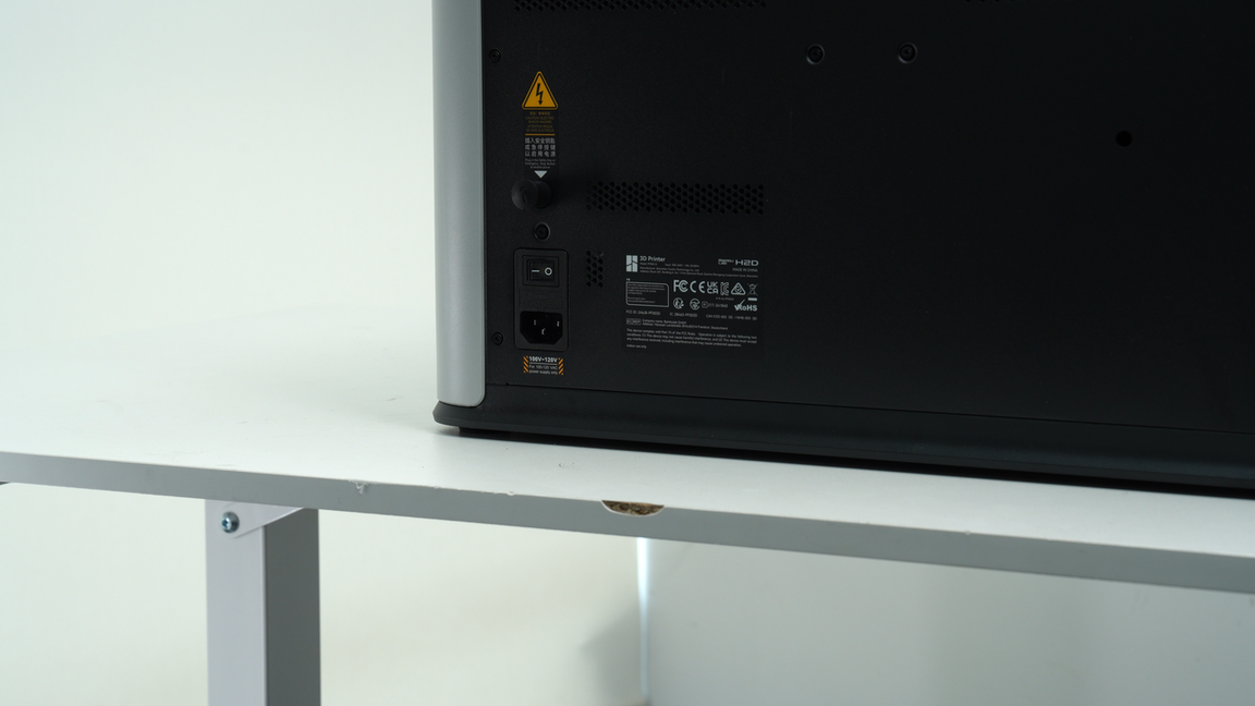
Lower the heatbed through the screen to facilitate the disassembly of the toolhead. Make sure the hotend is at room temperature and then power off the printer.
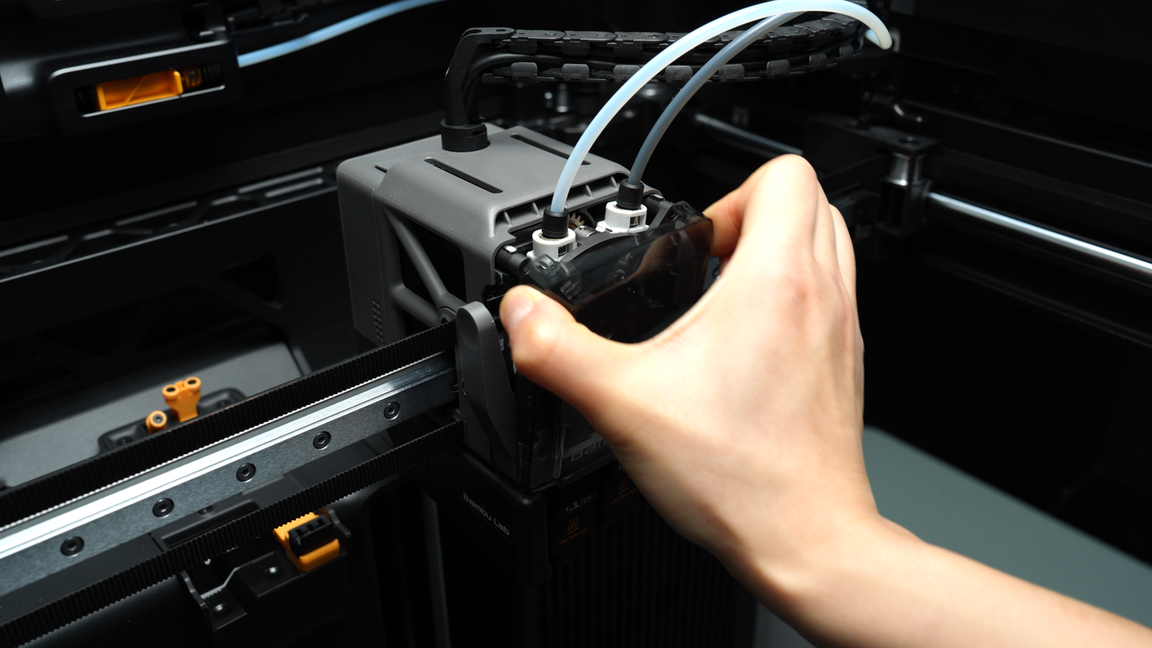
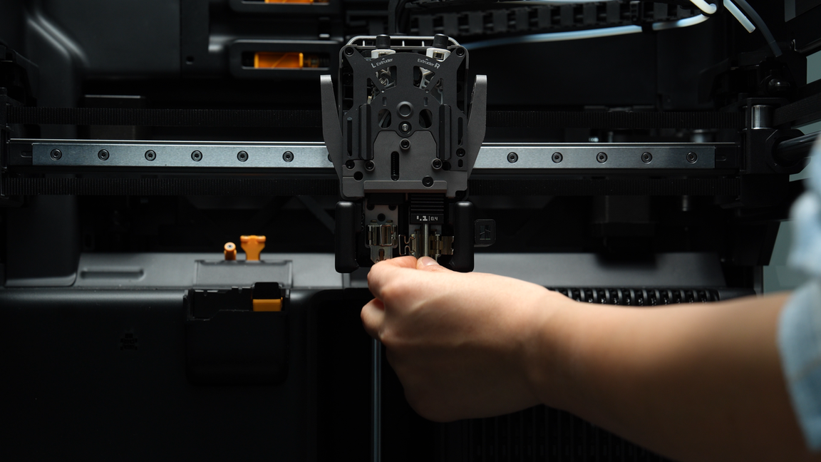
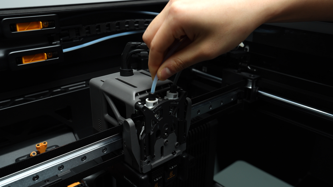
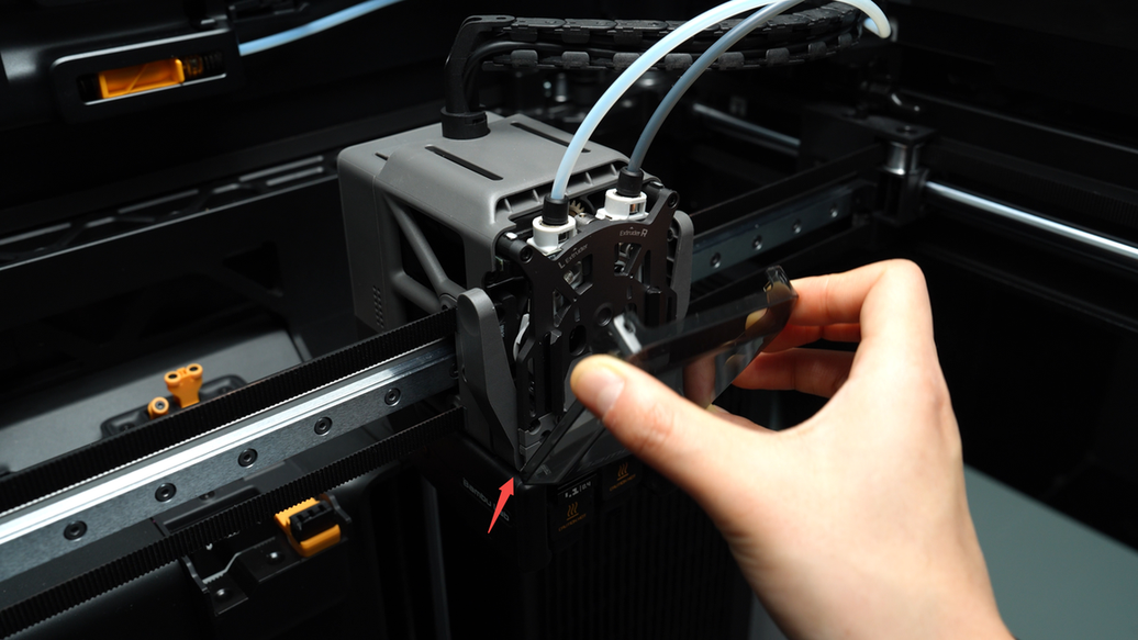
¶ Step 2: Remove the PTFE tube and the toolhead front cover
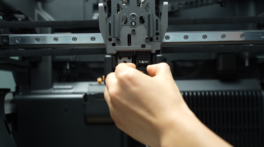
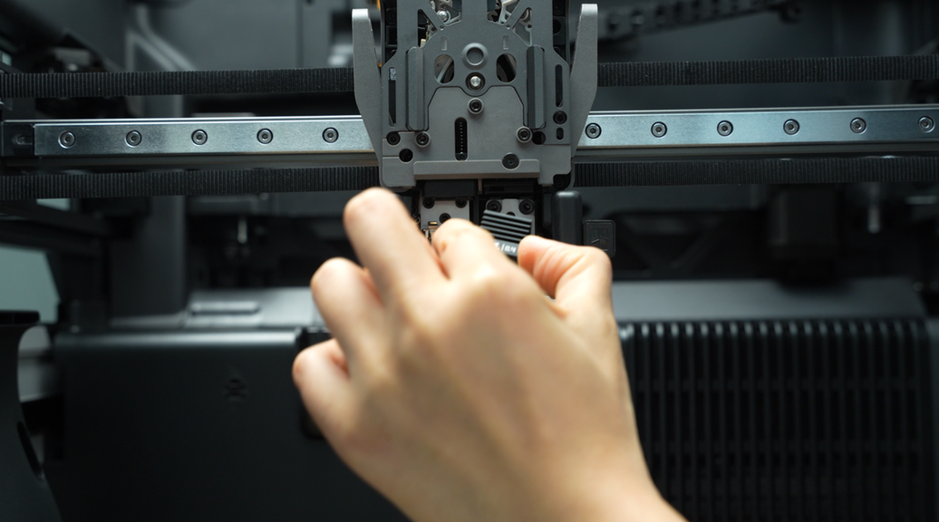
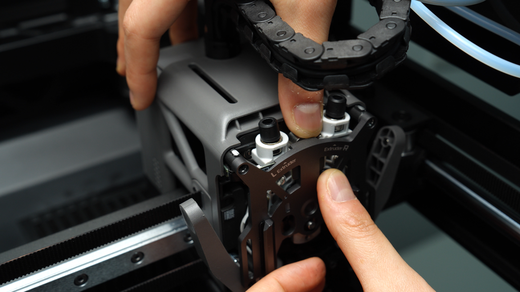
Pinch the top two corners of the toolhead front cover and lift upwards to remove the front cover.
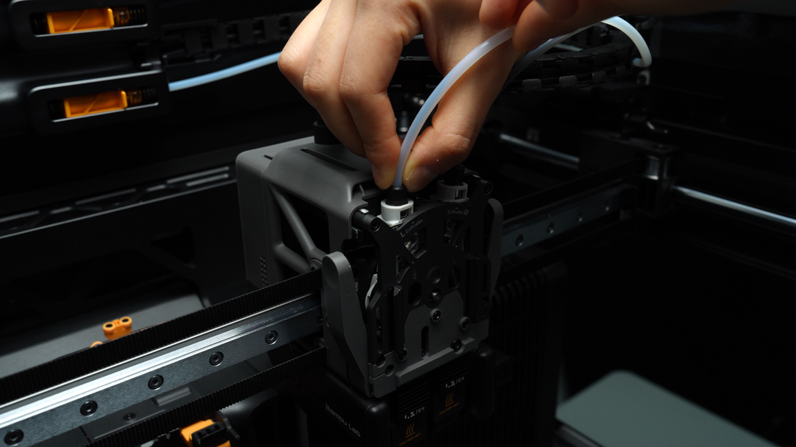
In a symmetrical manner, press down on the black outer ring to unlock the two connectors on the extruder, releasing the PTFE tube.
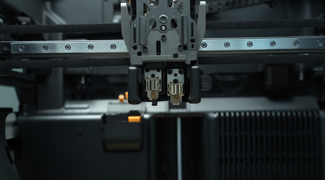
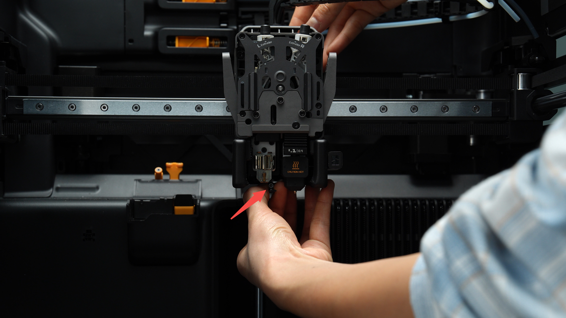
¶ Step 3: Remove the left and right hotends
The flow blocker is located on the lift connecting rod, and it moves left and right by toggling the connecting rod. If you need to remove a hotend but the flow blocker is blocking it, you must first move the flow blocker lever to clear the way before disassembling to prevent accidentally bending the flow blocker while removing the hotend. During toggling, the flow blocker may not fully move into position due to the tilt limit of the lever. In this case, a rough movement followed by fine adjustment is necessary to ensure the flow blocker is completely in place.
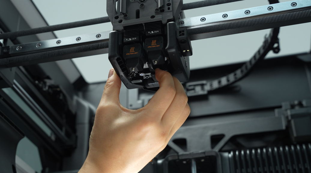
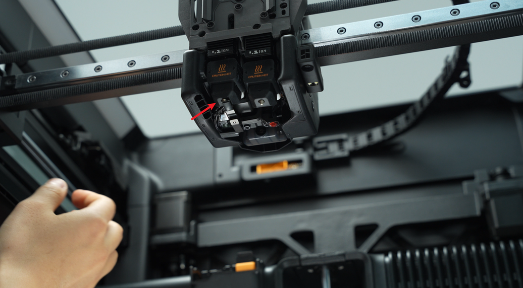
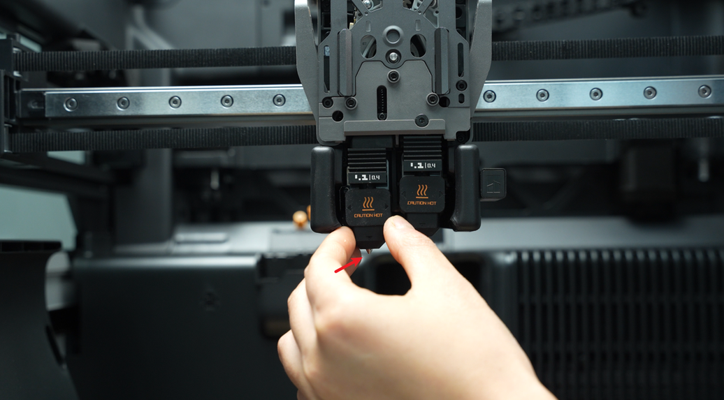
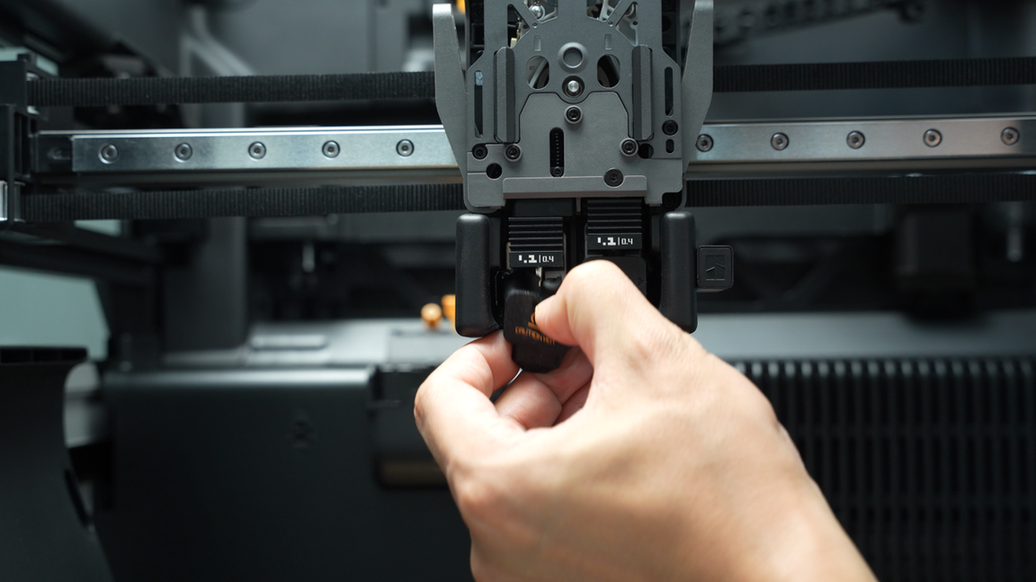
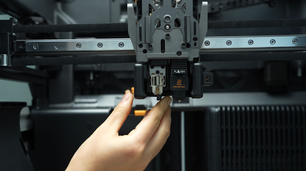
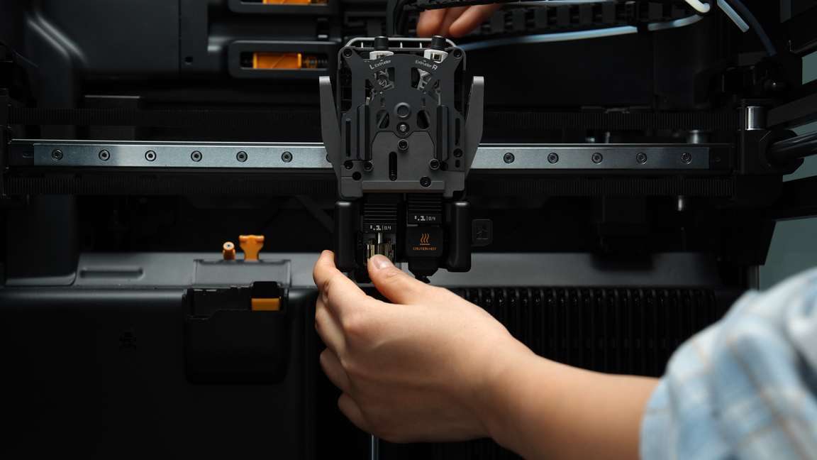
Before starting to remove the hotends, please press the cutters on both sides to cut the filament, making it easier to remove the hotends. Remove the silicone sock for hotend that is not blocked by the flow blocker, unlock the latch to remove the hotend, and pre-latch the latch of the heating assembly.
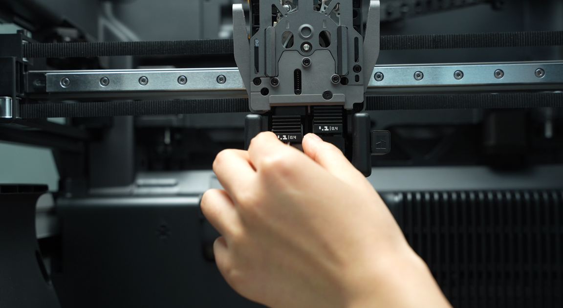
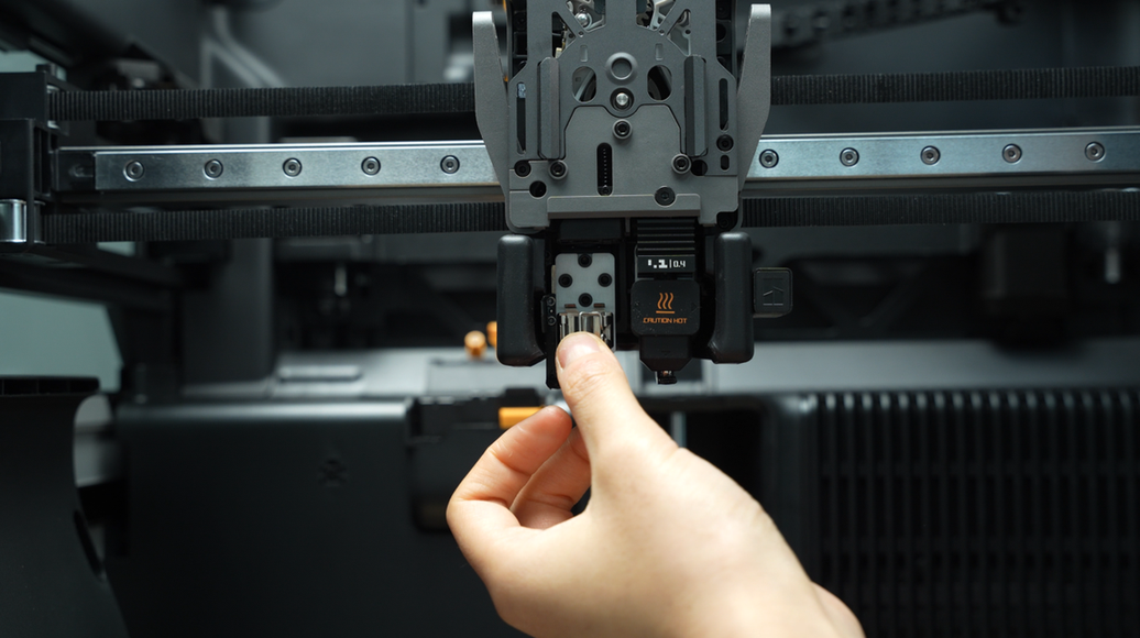
Toggle the flow blocker lever to move the flow blocker to the other side, remove the silicone sock of the remaining hotend, unlock the latch to remove the hotend, and pre-latch the latch of the heating assembly.
¶ Step 4: Remove the extruder filament guide and left cutter
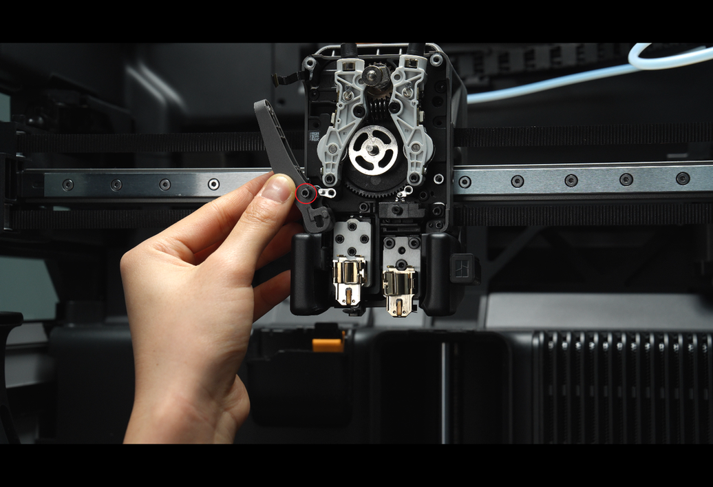
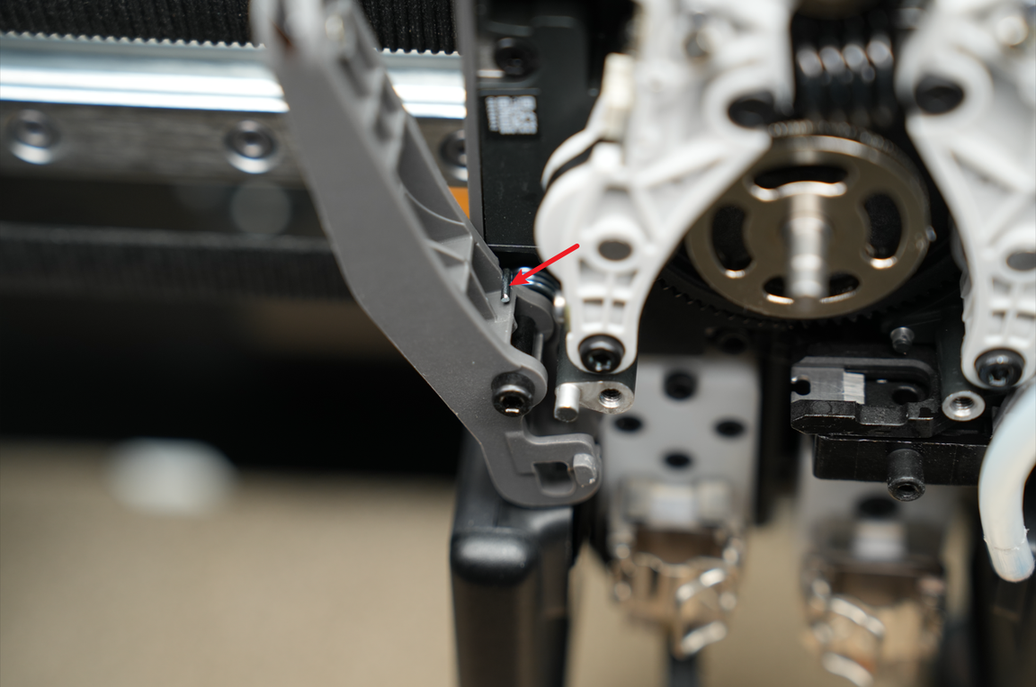
After unscrewing the four screws (M2.5x7 * 3;BT2x6 * 1) on the extruder filament guide, use your fingers to press upward against the black hotend connector while simultaneously pressing down on the left cutter lever to release it slightly from the opening slot near the cutter screw. Then, exert force outward from the lower right corner of the extruder filament guide to pry it out.
The left cutter is located within the extruder filament guide and will be removed together when removing the extruder filament guide. Please take care to store it properly to prevent loss.
¶ Step 5: Remove the extruder front cover
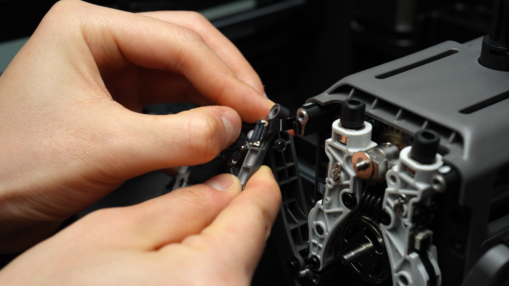
Unscrew the two screws (M2.5x7) on the extruder front cover. Please be careful when removing the extruder front cover to prevent the FPC cable from being torn off. Then release the FPC cable latch to remove the extruder front cover.
¶ Step 6: Remove the right cutter and the left and right cutter levers
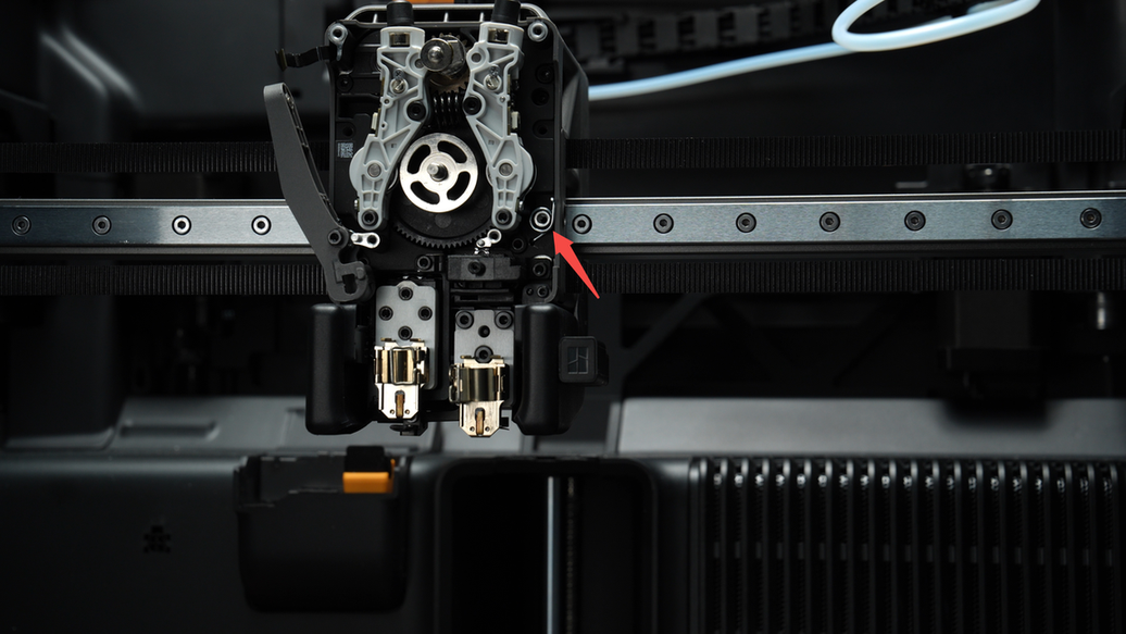
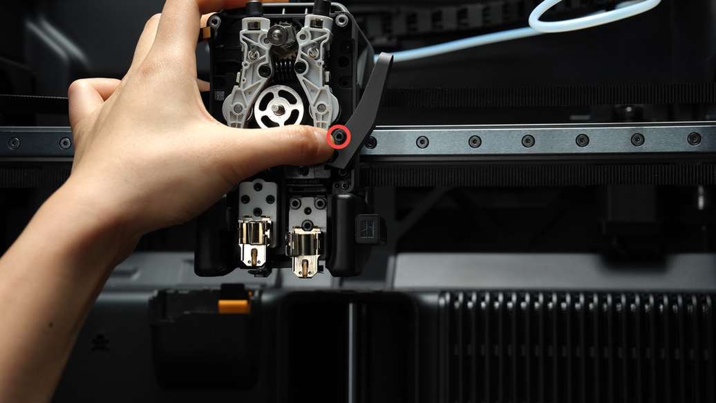
Unscrew the screw (MG2.5x19x5) of the right cutter and remove the right cutter and lever. Unscrew the screw (MG2.5x19x5) of the left cutter and remove the left lever. When removing the cutters, please remember to store the cutter springs installed inside carefully.
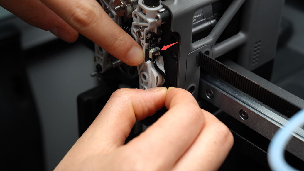
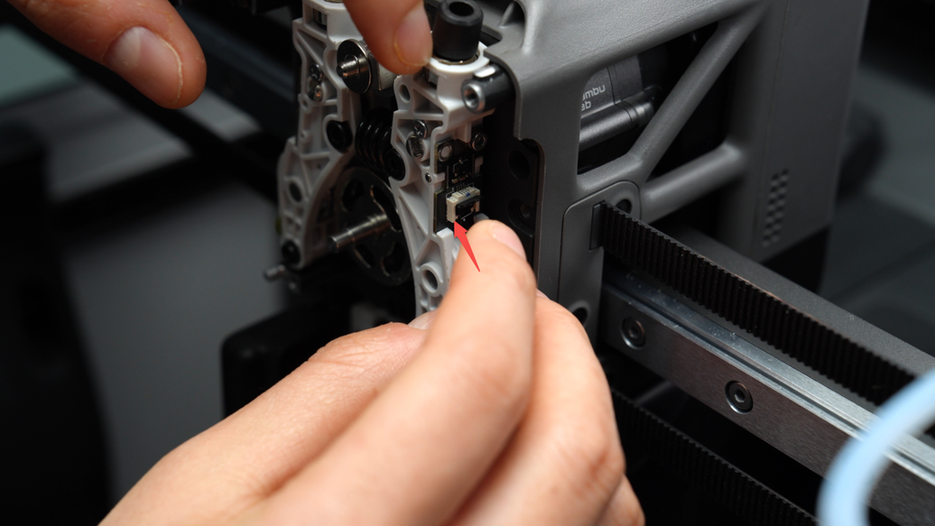
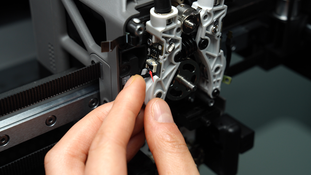
¶ Step 7: Loosen the Hall sensor cable screws on the extruder idlers and unplug the Hall sensor connector.
Unscrew the two hall sensor cable screws (BT2x5) on the dual extruder idlers and loosen the connector of the Hall sensor. Carefully remove the FPC cable from the connector to avoid damaging it.
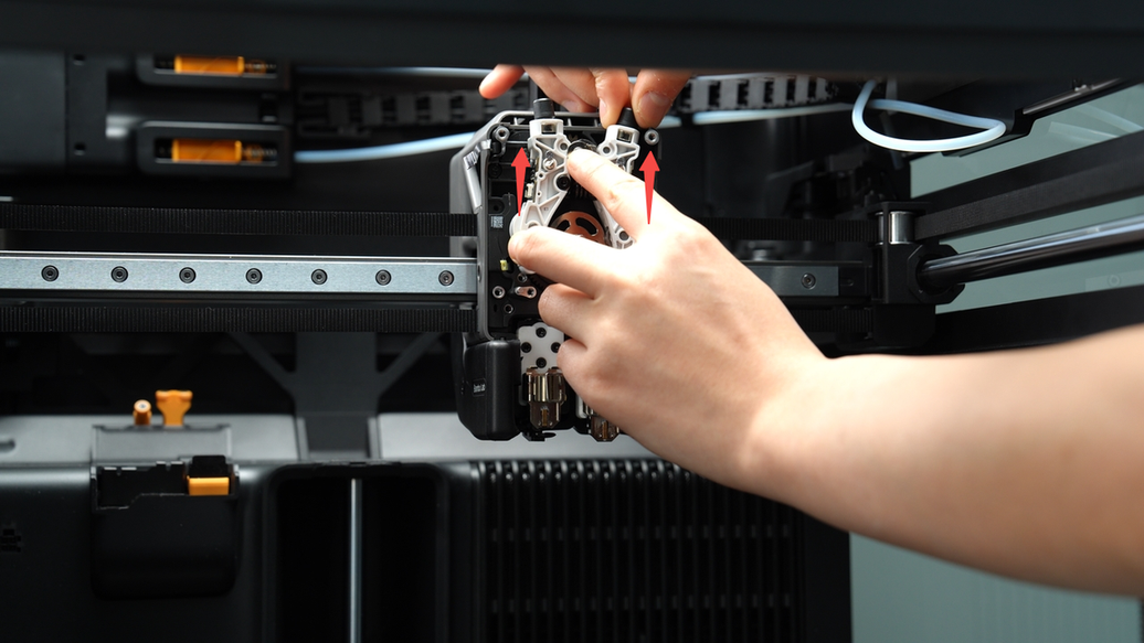
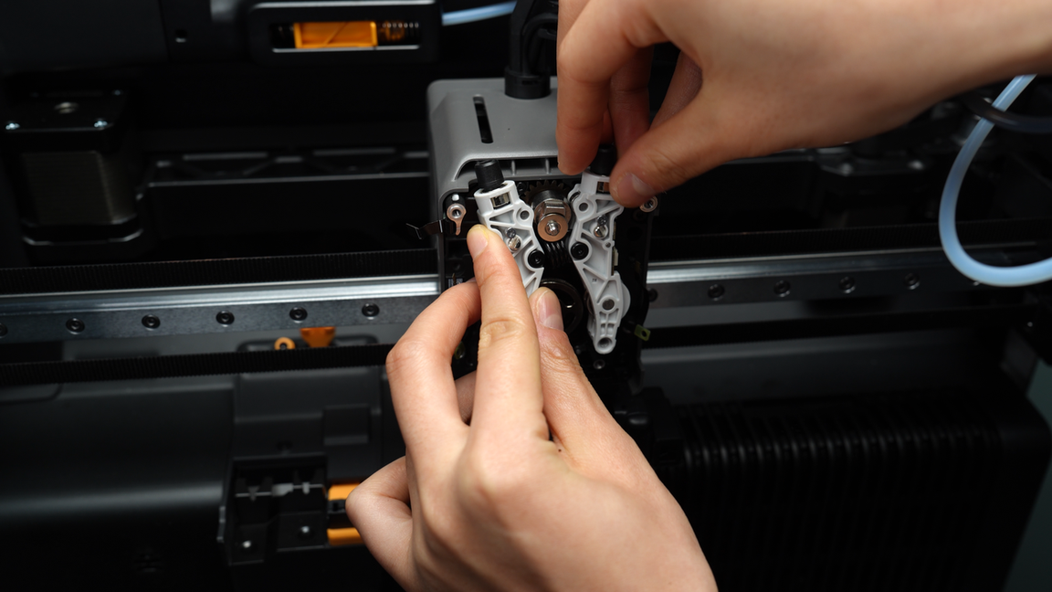
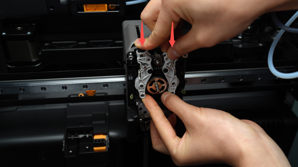
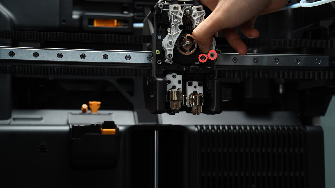
¶ Step 8: Remove the dual extruder idlers and the extruder switch cam
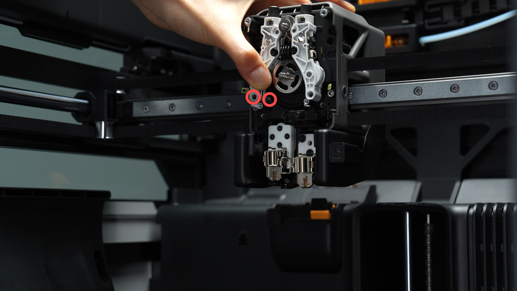
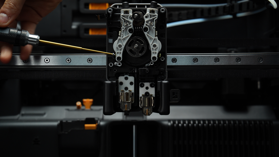
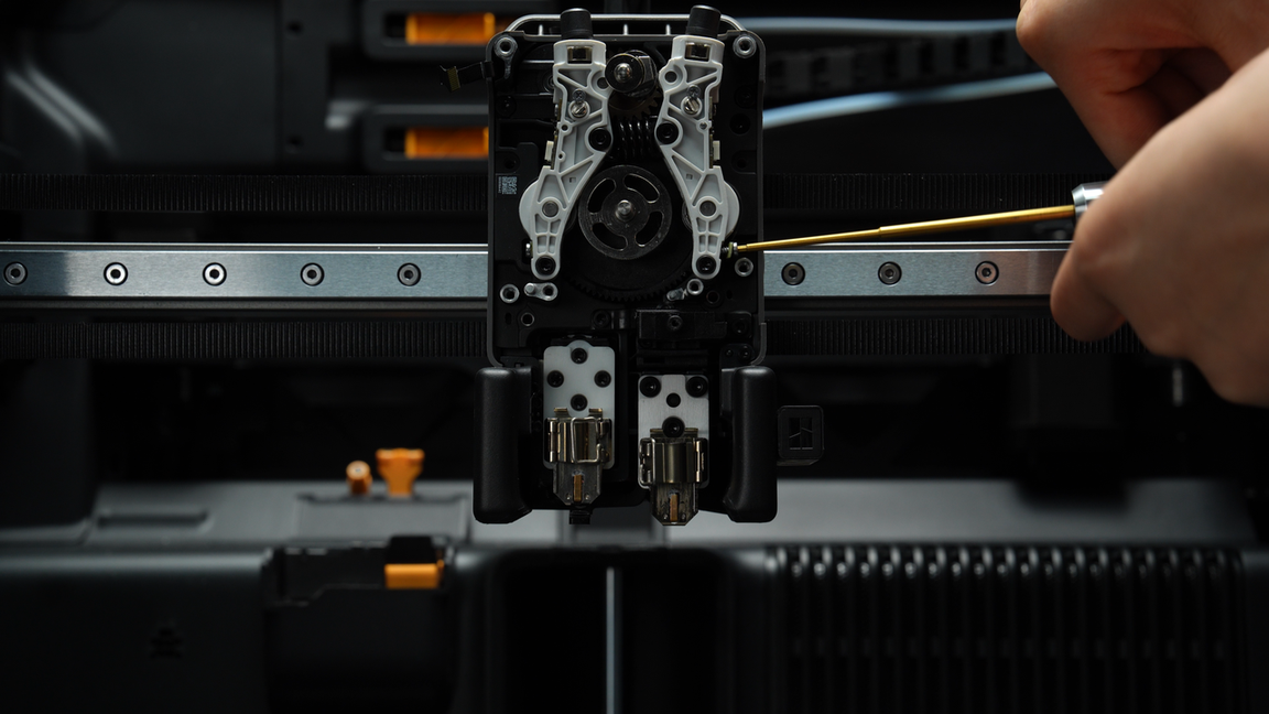
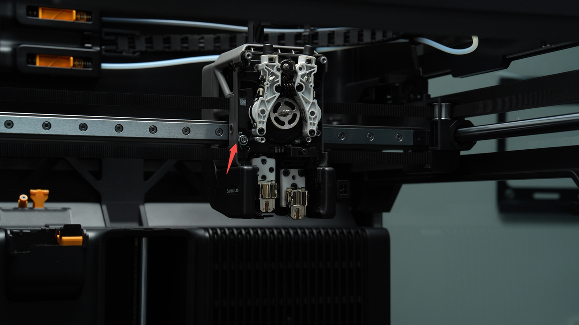
Unscrew the two fixed screws (M2.5x19x5) located beneath the extruder idlers, then gently push the extruder idlers upwards by hand to remove it along with the extruder switch cam simultaneously.
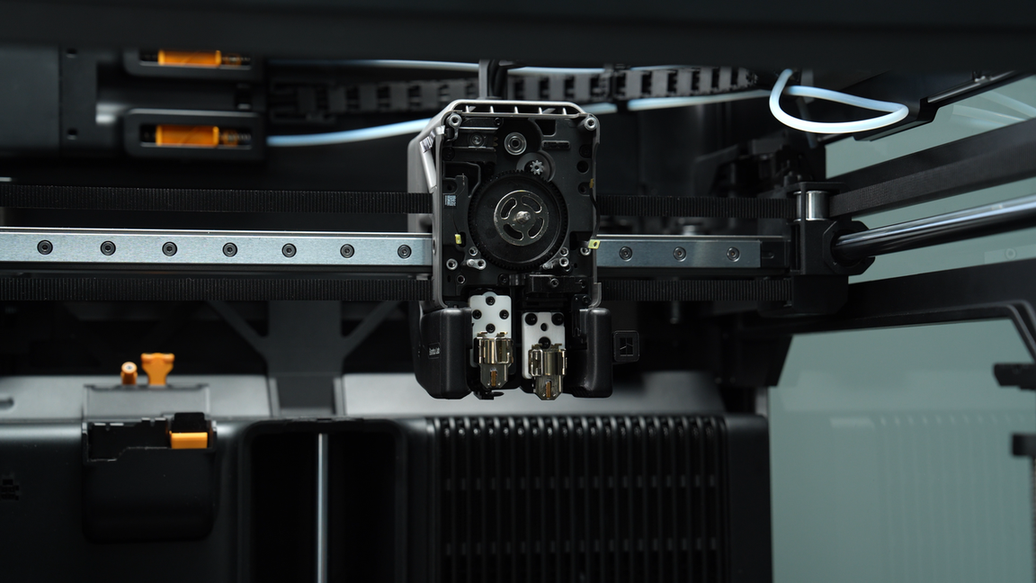
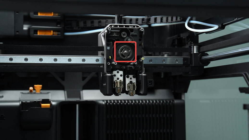
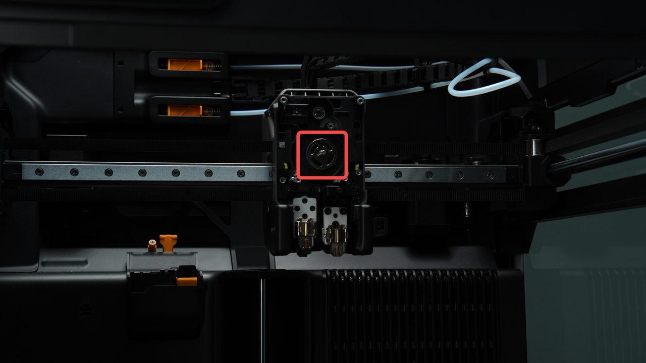
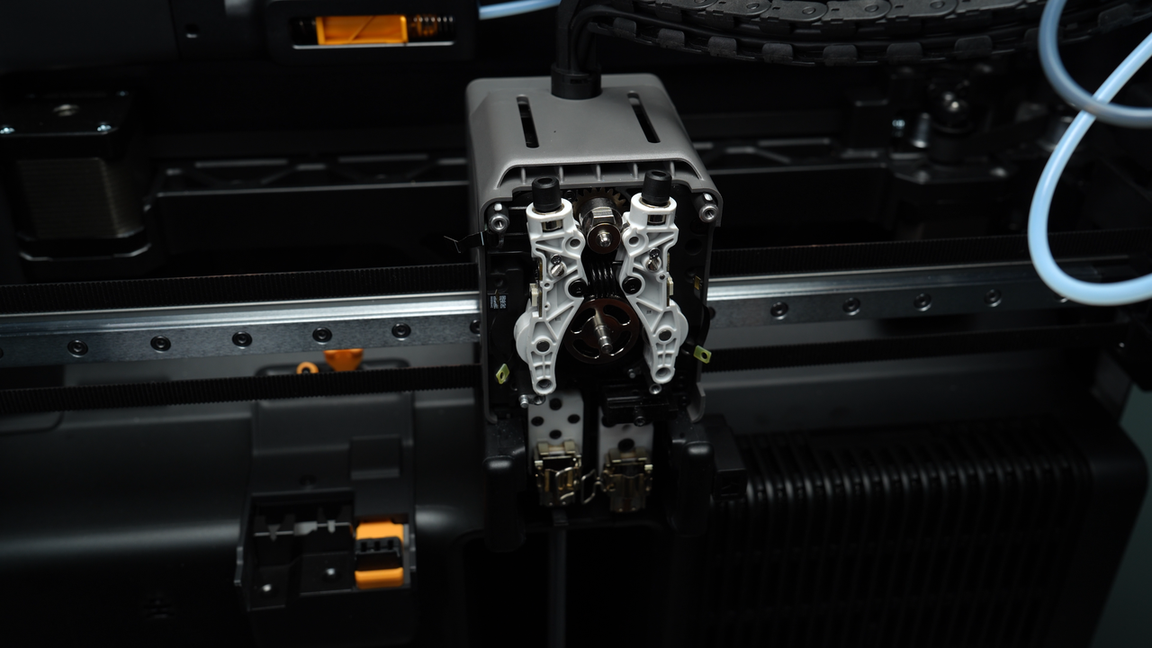
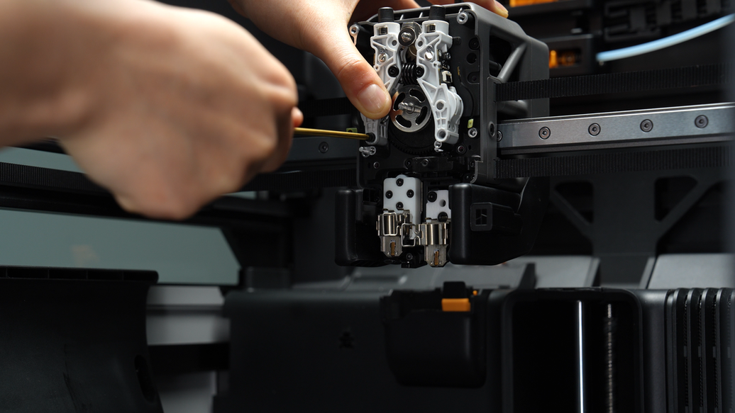
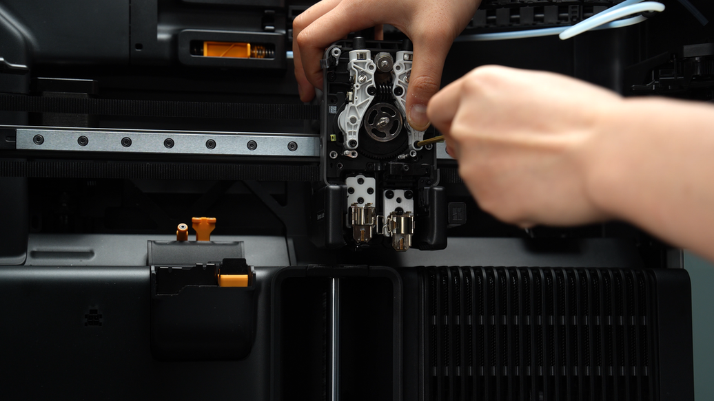
¶ Step 9: Remove the extruder gear
Lastly, remove the extruder gear.

¶ Assembly steps
¶ Step 1: Install the extruder gear
Reinstall the extruder gear back into the gear slot.
¶ Step 2: Install the extruder switch cam and the dual extruder idlers
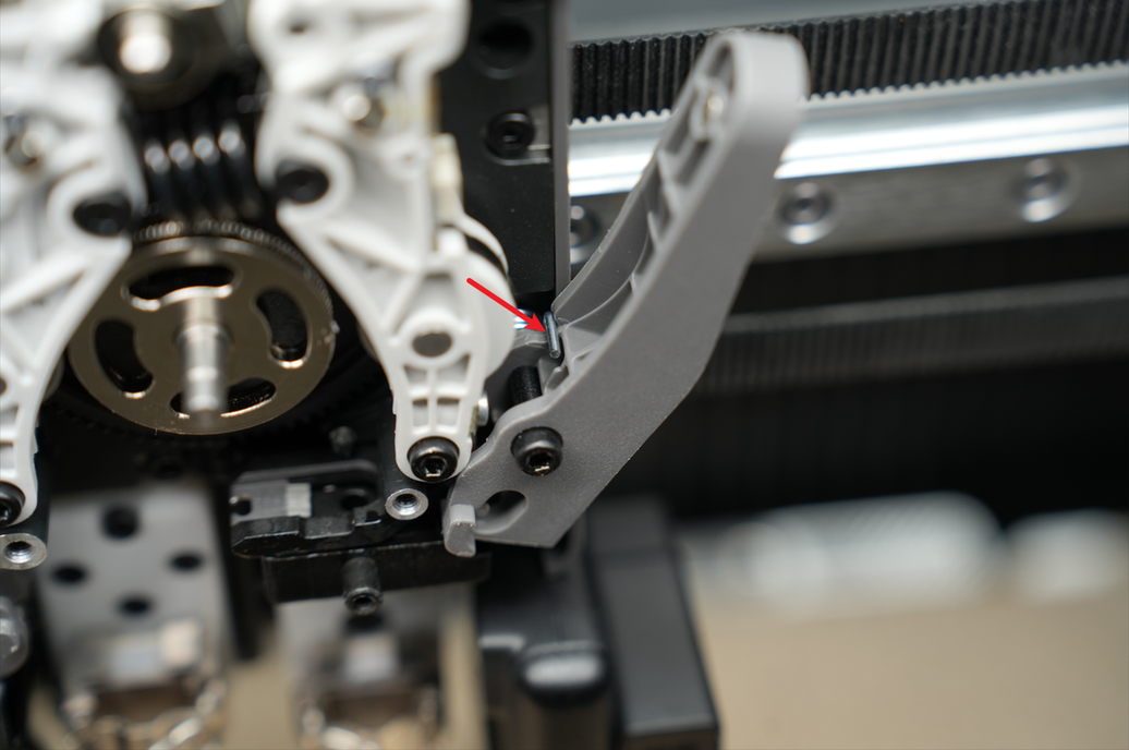
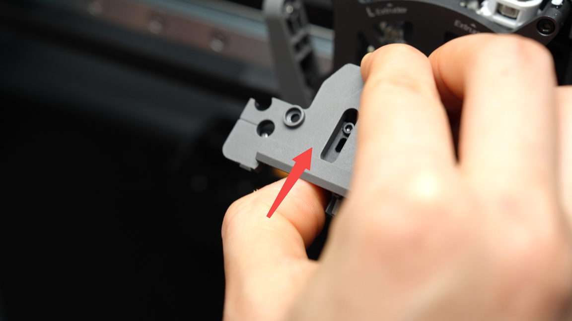
First reinstall the extruder switch cam, ensuring that the flat surface in the picture below is horizontal. A deviation of around 5 degrees to the left or right is acceptable, it does not need to be perfectly level.
Insert the spring of the extruder idlers into the location below the cam, matching arc to arc. Then push down firmly on the extruder idlers. When you hear a "click" sound indicating a proper fit, the extruder idlers are installed correctly.
To install the left and right idler fixed screws (M2.5x19x5), align the screw holes on the idler with those on the frame before smoothly tightening the screws. You can also slightly pull out the extruder idlers forward for better visibility of the screw holes from the side.
When installing the left idler screw, avoid fully tightening it to maintain some mobility on the right idler, facilitating the insertion of the right idler screw. Once the right idler screw is fully tightened, proceed to fully tighten the left idler screw again.
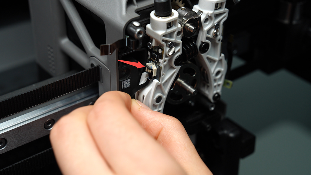
¶ Step 3: Reinsert the plugs of the left and right hall boards, and tighten the hall sensor cable screws
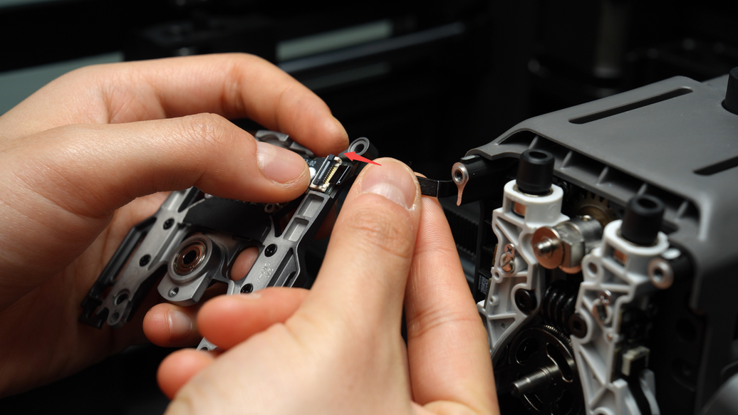
Reinsert the FPC cable into the plug of the hall sensor board, ensuring that the end of the FPC cable is fully inserted into the plug before closing the socket. The white line on the FPC cable is in a horizontal position, indicating that the FPC cable is inserted correctly.
Tighten the hall sensor cable screws (BT2x5) on the extruder idlers.
¶ Step 4: Install the right cutter and the left and right cutter levers
Reinstall the left cutter spring, align the holes on the lever with the screw holes, then tighten the screws (MG2.5x19x5). When installing the left cutter lever, the left torsion spring upper arm should rest against the left cutter lever.
Pay attention to distinguish between the left and right cutter springs and the left and right cutter levers. The upper arm of the left torsion spring is positioned to the left, while the upper arm of the right torsion spring is positioned to the right. The left cutter lever is longer than the right cutter lever.
If the cutter screws are tightened too much, it may cause the cutter to get stuck. In such a situation, simply loosen the screws slightly to resolve the issue.
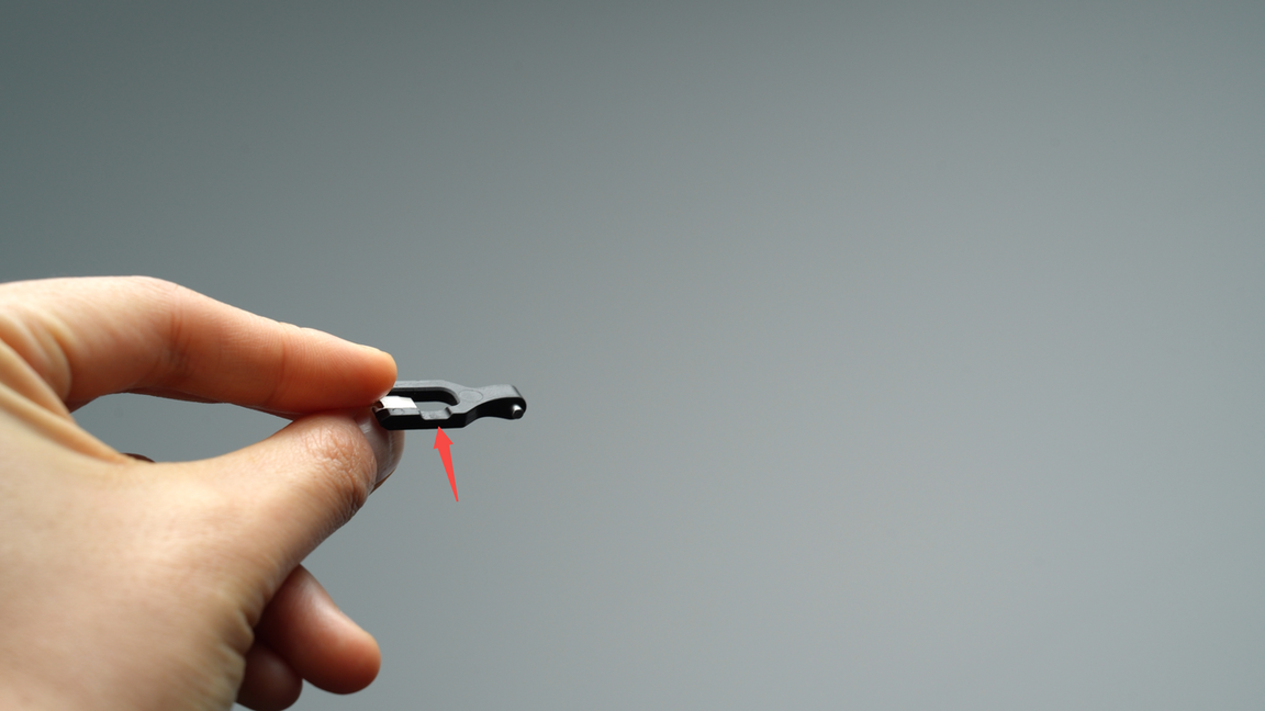
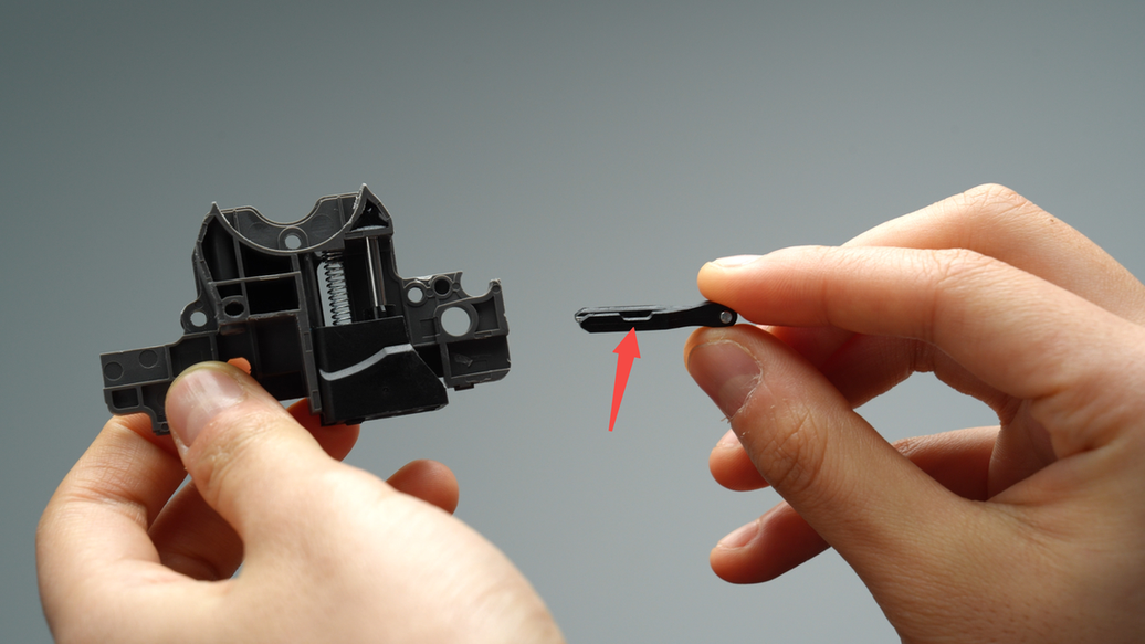
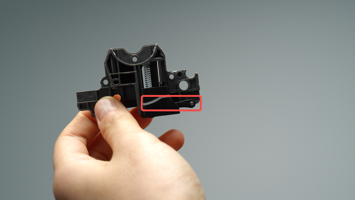
Next, install the right cutter and the right cutter lever (Please note that the cutter blade itself does not distinguish between left and right). When installing the cutter, make sure that the notch of the cutter faces upwards, then place it into the cutter slot of the lever.
Reinstall the right cutter spring, align the holes on the right cutter lever with the screw holes, then tighten the screw (MG2.5x19x5). When installing the right cutter lever, the right torsion spring upper arm should rest against the right cutter lever.
¶ Step 5: Install the extruder front cover
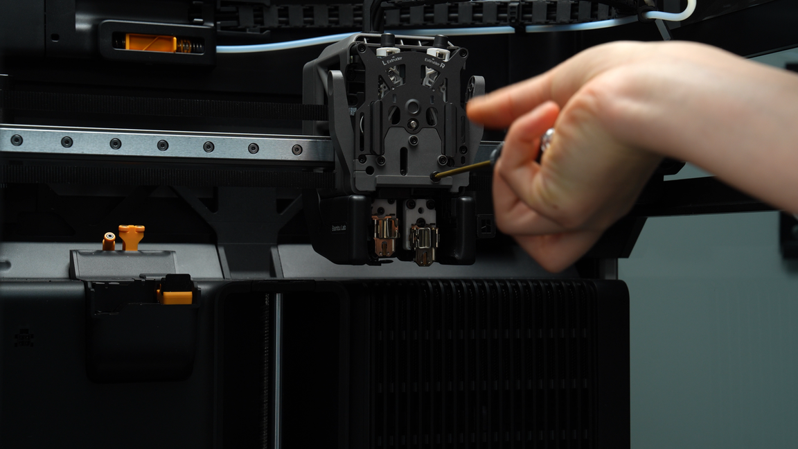
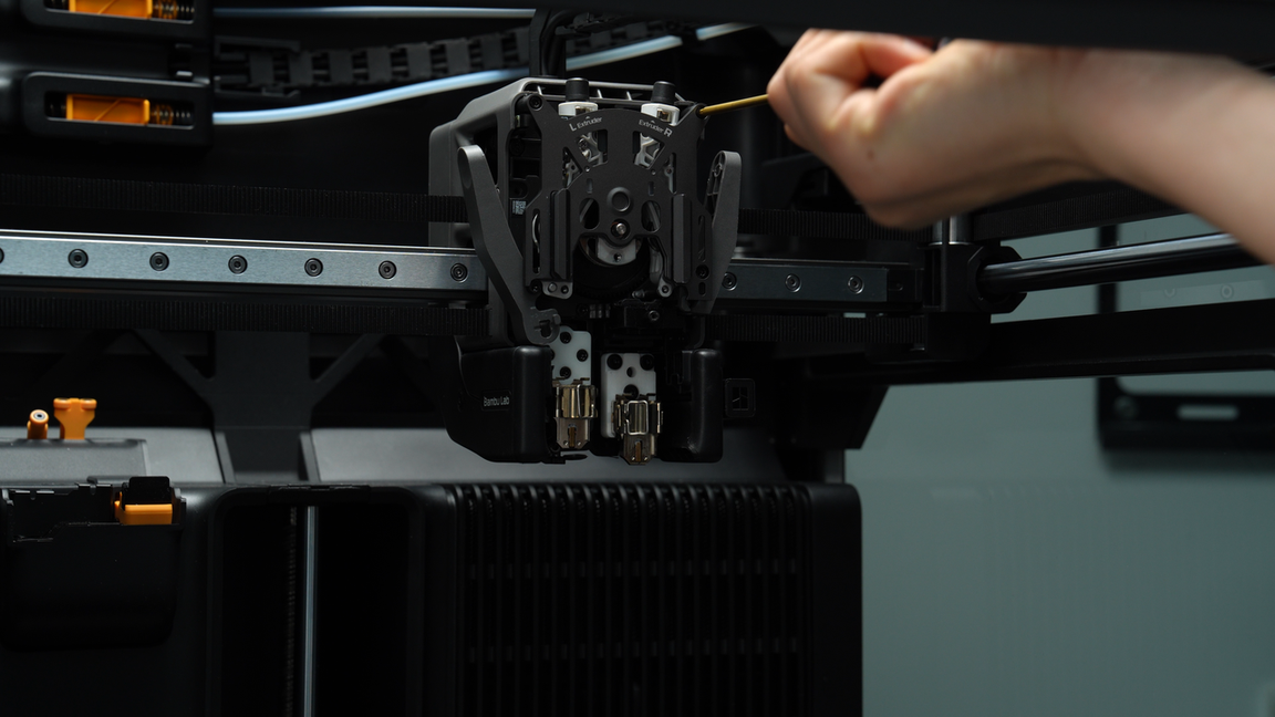
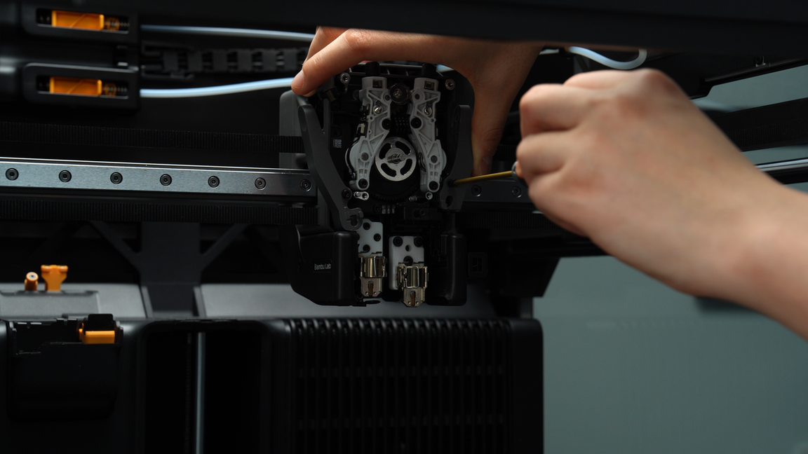
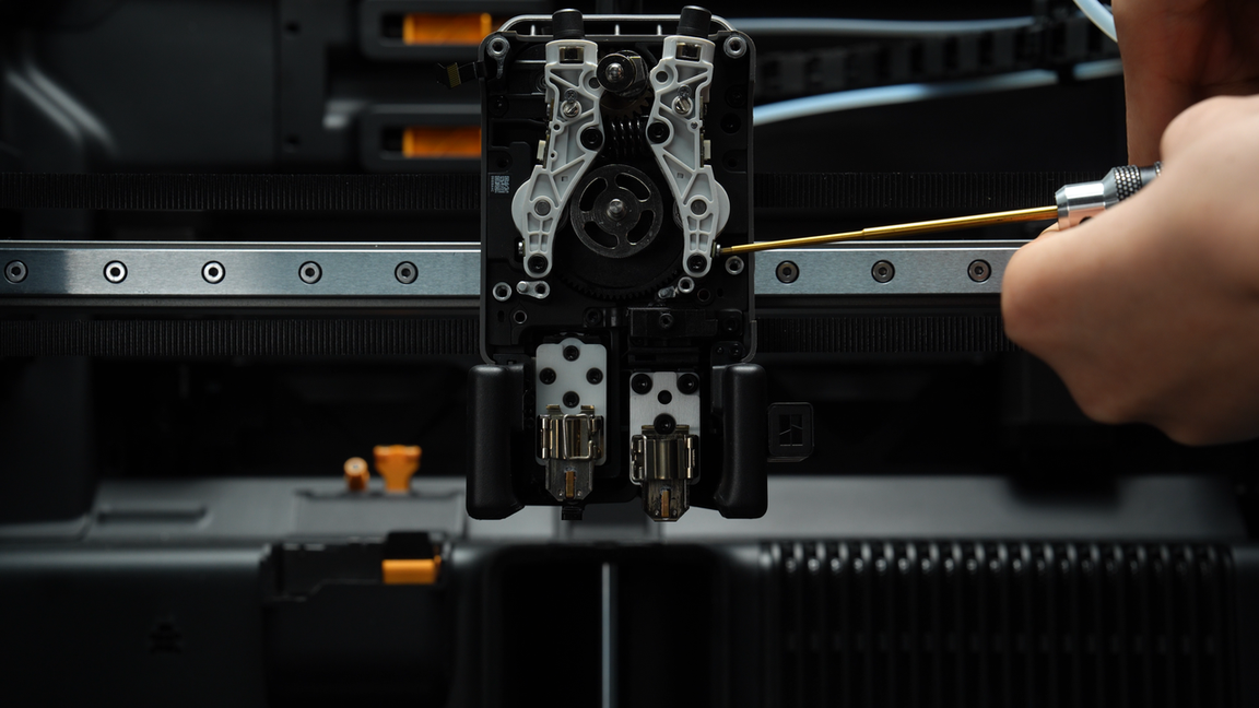
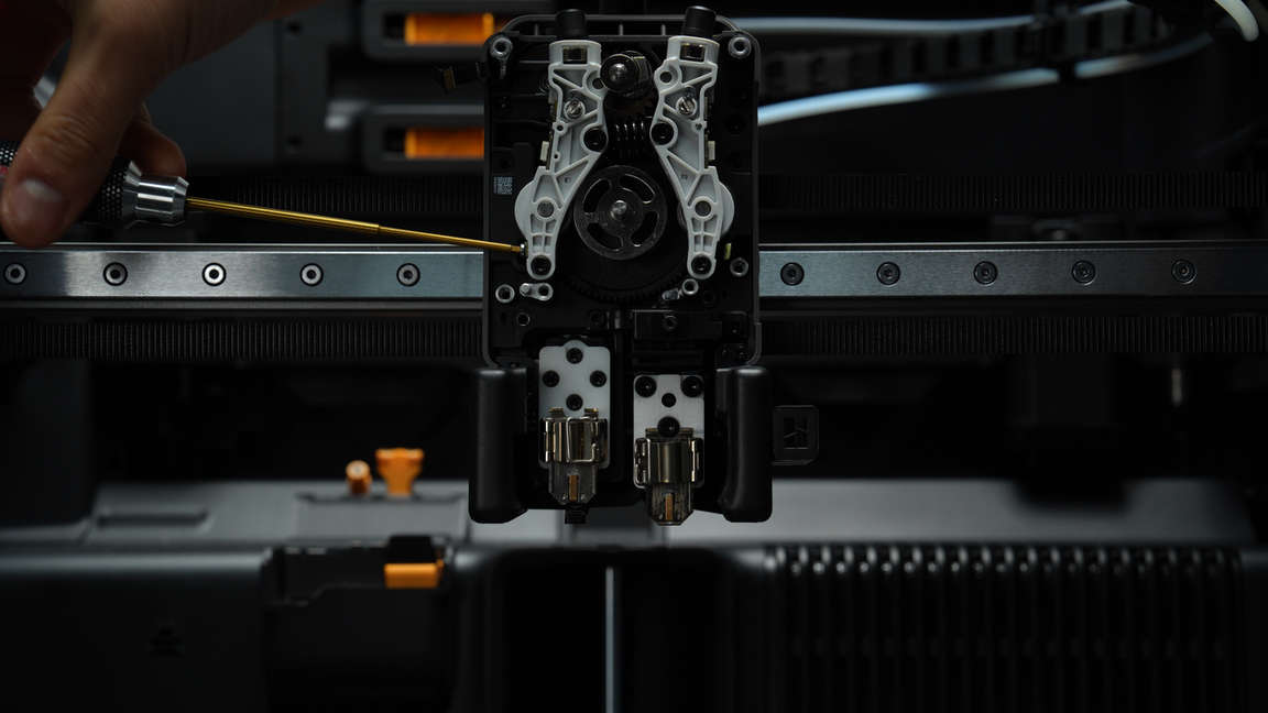
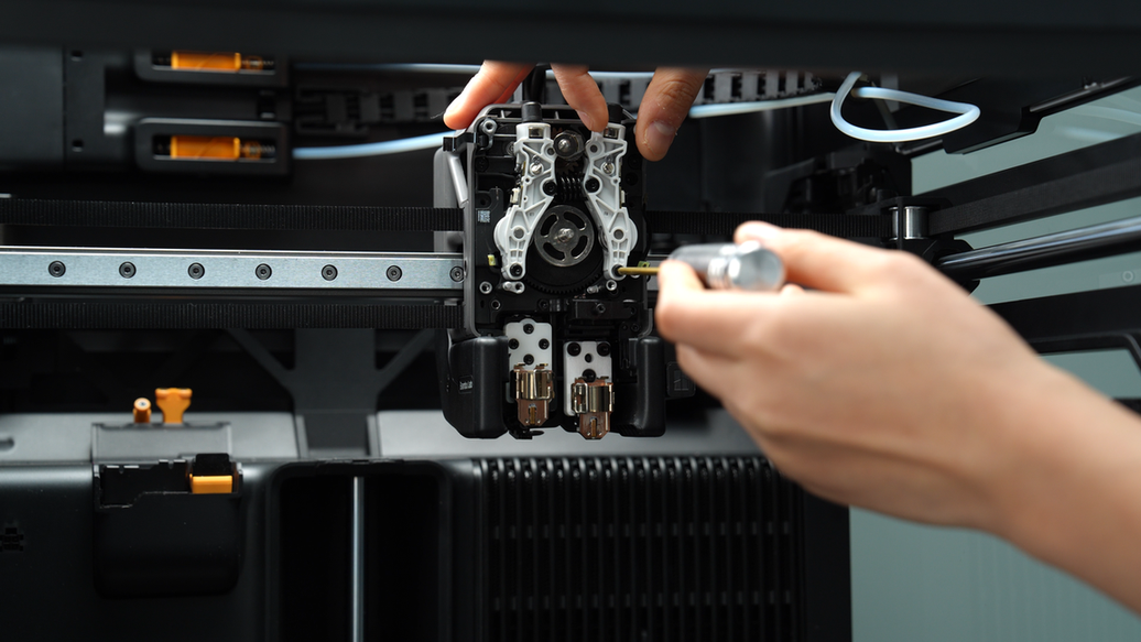
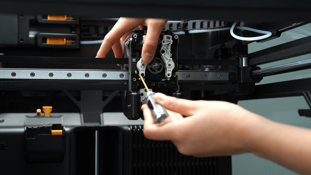
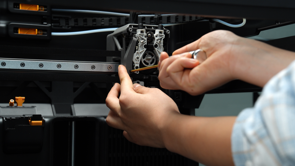
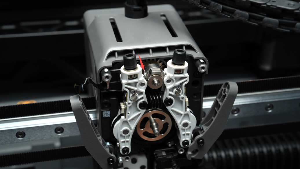
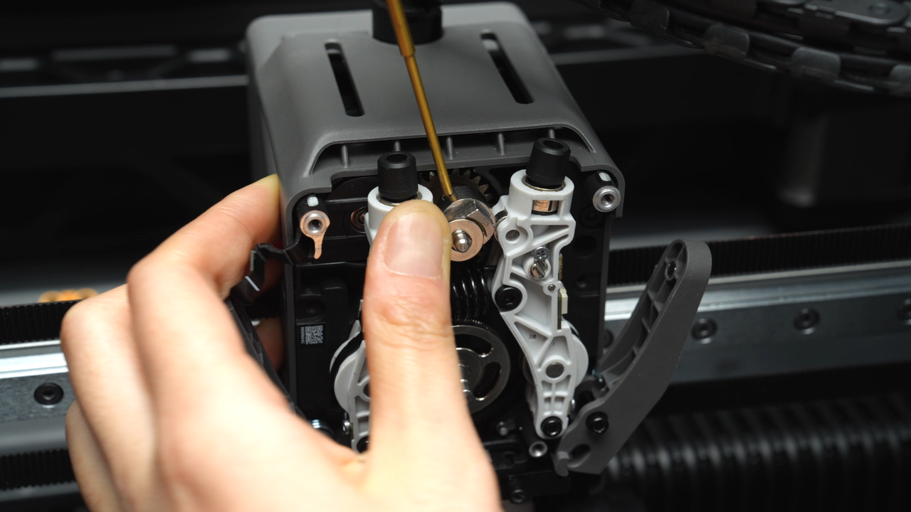
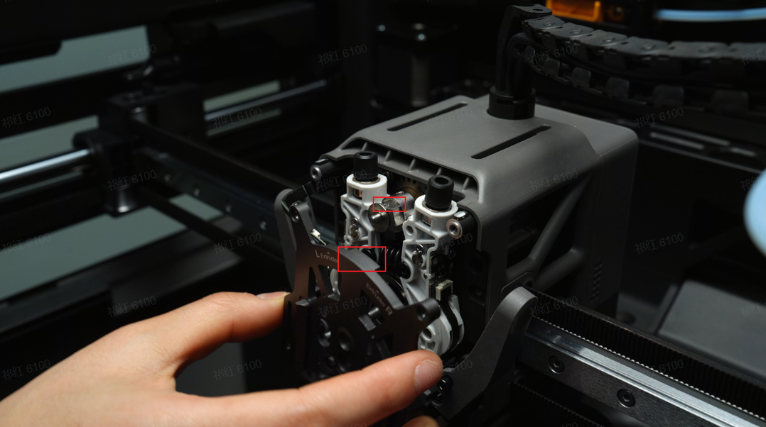
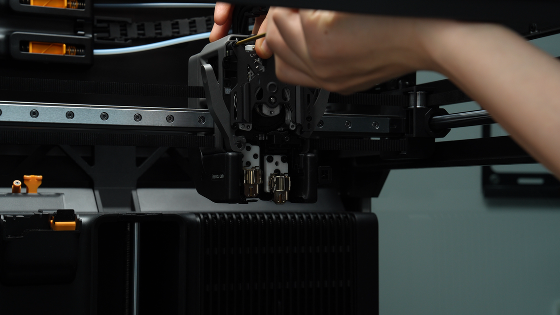
Before installing the extruder front cover, it is necessary to adjust the angle of the extruder switch cam using an Allen key for easier installation later on.
Insert the Allen key into the small hole of the cam, hold the left extruder idler with your hand, and rotate it until the cam surface is parallel to the extruder idler.
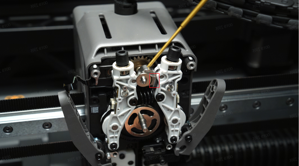
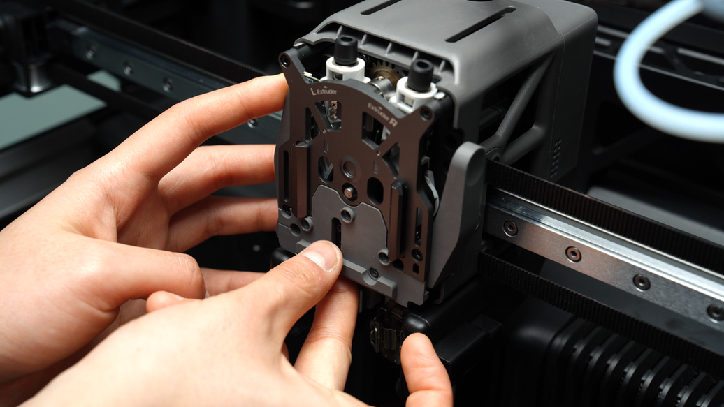
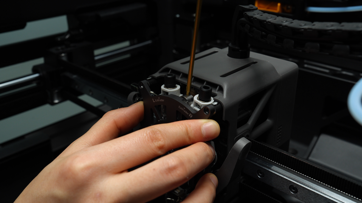
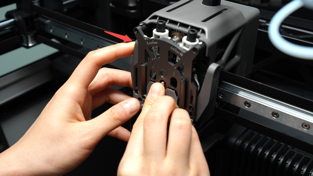
Insert the FPC cable into the extruder front cover connector, ensuring that the head of the FPC cable is fully inserted into the connector before locking it in place. The white line on the FPC cable is in a horizontal position, indicating that the FPC cable is inserted correctly. When installing the extruder front cover, ensure that the convex surface of the front cover, as shown in the picture below, remains parallel to the side of the cam.
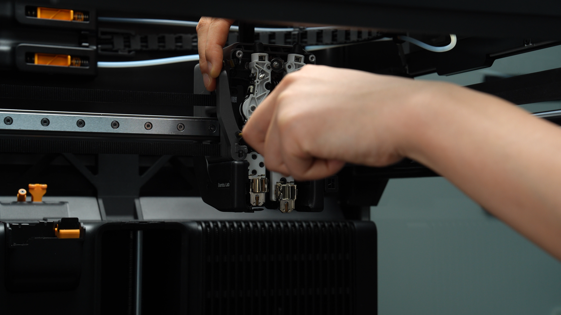
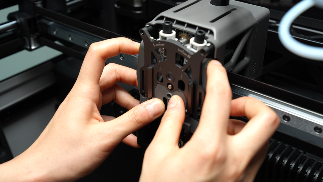
Then you can adjust this alignment by inserting an Allen key into the small hole until the extruder front cover snaps into the correct position.
Fold the side FPC cable, neatly organize it, and tuck it into the gap on the side of the toolhead.
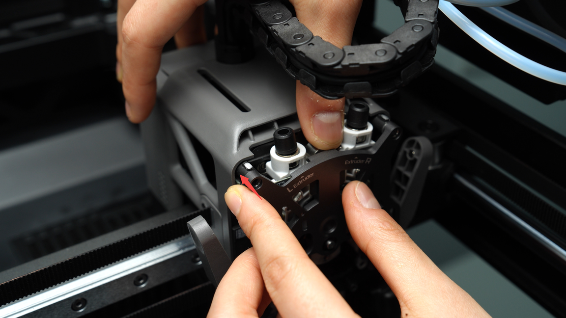
Tighten the two screws (M2.5x7) on the extruder front cover.
¶ Step 6: Install the extruder filament guide and the left cutter
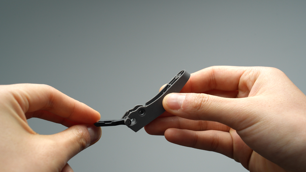
The left cutter needs to be installed together with the extruder filament guide. Ensure that the notch of the left cutter is facing upwards, then place it into the cutting blade slot of the extruder filament guide.
When installing the extruder filament guide, make sure to continuously press upwards against the black hotend connector and simultaneously press the left cutter lever, adjusting it to an appropriate angle for easy insertion. Then, install the extruder filament guide. Finally, press on both sides of the cutter lever, applying force to completely flatten the front cover.
Then, tighten the four screws (M2.5x7 * 3;BT2x6 * 1) on the extruder filament guide.

¶ Step 7: Install the left and right hotends
Same as the disassembly process, if you need to install a hotend and the flow blocker is obstructing it, you must first move the flow blocker connecting rod to move the flow blocker aside before proceeding with the installation. This prevents accidentally bending the flow blocker when removing the hotend. When moving it, the flow blocker may not fully disengage at once due to the lever's tilted position. In such cases, rough movement should be followed by fine adjustments to ensure the flow blocker is completely in place.
Install the right nozzle, lock the nozzle latch and put on the silicone sock.
Move the flow blocker connecting rod to shift the flow blocker to the other side, then install the left nozzle. Lock the nozzle latch and put on the silicone sock as well.
Please note that when installing the silicone sock on the left hotend, ensure that the sock is not tilted to prevent deformation of the adjacent baffle.
¶ Step 8: Install the PTFE tube and the toolhead front cover
Connect the two PTFE tubes, with the PTFE tube above the cable chain connecting to the right extruder and the PTFE tube below the cable chain connecting to the left extruder.
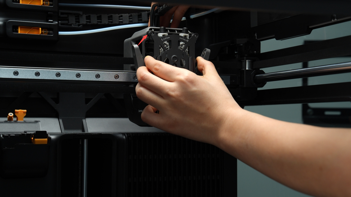
When reinstalling the front cover of the toolhead, first position it under the extruder and then push it back to secure the front cover in place.
¶ How to verify completion/success
Restart the printer and switch the left and right extruders on the screen, and load filament to verify that everything is functioning correctly.
¶ End Notes
We hope the detailed guide provided has been helpful and informative.
If this guide does not solve your problem, please submit a technical ticket, we will answer your questions and provide assistance.
If you have any suggestions or feedback on this Wiki, please leave a message in the comment area. Thank you for your support and attention!