¶ Issue Description
The left hotend is secured to the hotend heater with a locking clip and moves up and down with the hotend lifting module. When the left extruder is operational, the hotend lifting module descends, approaching the rear left extrusion force eddy current sensor, maintaining a specific gap. This gap changes correspondingly with variations in extrusion force, enabling extrusion force measurement. If the sensor detects an extrusion force signal with excessively low frequency, the system will trigger an alarm, causing the heatbed to slightly descend, terminate the task, and display an error message.
Possible causes of the issue include:
-
Excessive gap between the left extrusion force sensor eddy current coil and the hotend lifting module.
-
Disconnection or looseness between the left extrusion force sensor and the TH board.
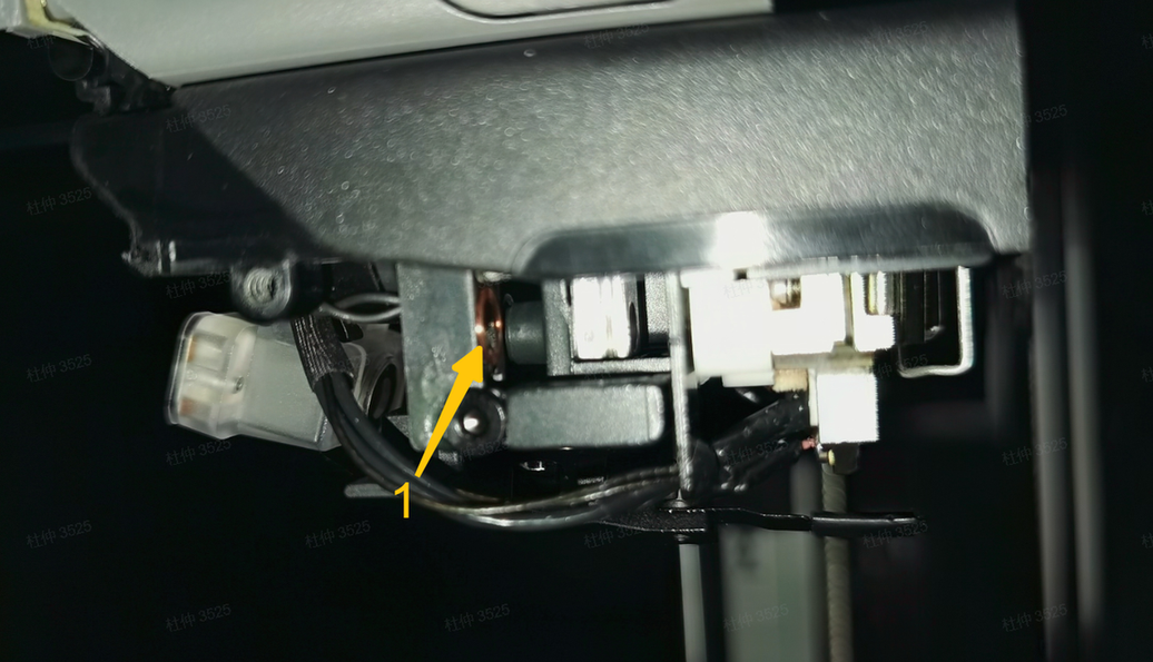 1- Left extrusion force sensor eddy current coil |
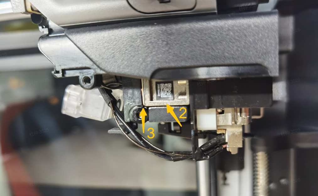 2- Hotend lifting module, 3- Gap between eddy current coil and lifting slider |
|---|
¶ Troubleshooting
Before disassembling the toolhead, ensure the printer is powered off.
¶ Tools, Equipment and Materials
-
H2.0 Allen key
-
Standard A4 printing paper
¶ Solutions
Users may adjust the order of these solutions as needed.
¶ Step 1. Inspect the Gap Between the Eddy Current Coil and the Lifting Slider
-
Refer to Steps 1-4 in the Wiki Disassemble the H2D toolhead to remove the part cooling fan duct.
-
Check the gap between the left extrusion force sensor eddy current coil and the left hotend lifting slider. The normal gap range:
-
With the left extruder in the working position.
-
Two layers of standard printing paper (total thickness: 0.2mm) can slide smoothly.
-
Three layers of printing paper (total thickness: 0.3mm) cannot be inserted or experience noticeable friction when inserted.
-
-
Gently attempt to tighten the screw (see Figure 2 below) with an H2 Allen key to check if it is loose.
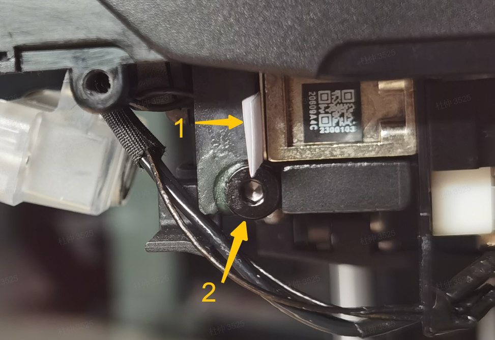
1 - Two layers of standard A4 paper 2 - Rear locking screw of the coil bracket
-
If the gap is abnormal or the screw is loose, adjust as follows:
-
Loosen the screw and place three layers of standard printing paper (total thickness: 0.25-0.3mm) between the eddy current coil and the lifting slider.
-
Push the coil bracket toward the lifting slider and tighten the screw.
-
After tightening, remove the paper and confirm the gap is appropriate using two and three layers of paper (refer to the gap check above).
-
Finally, secure the screw with structural adhesive to prevent loosening.
-
-
If the gap is normal and the screw is not loose, proceed to Step 2.
¶ Step 2. Check for Looseness in the Connection Between the Left Extrusion Force Sensor and the TH Board
-
Refer to Steps 4-5 in the Wiki Disassemble the H2D toolhead to remove the part cooling fan and its TH connection board, exposing the TH board.
-
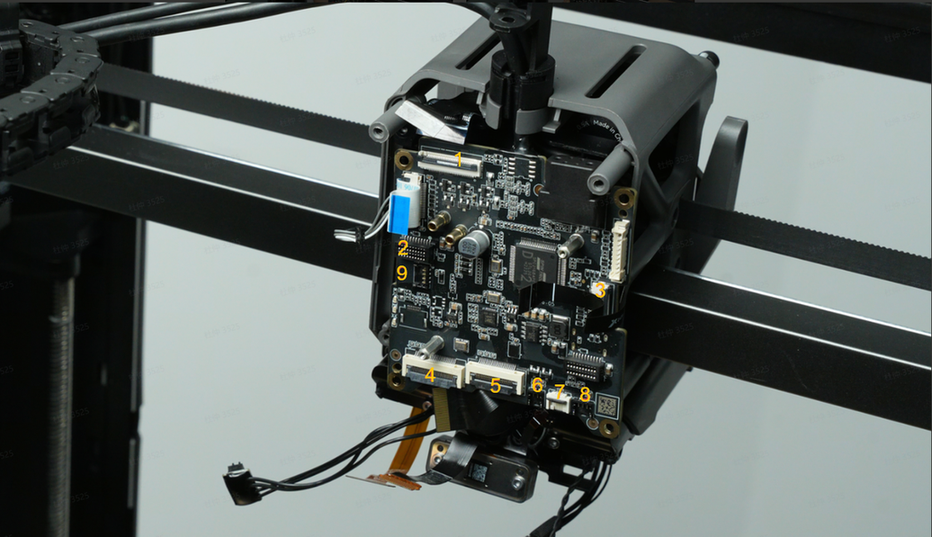
Inspect the left extrusion force sensor connector at the bottom of the TH board (Connector 8 in the image below).
-
If the sensor connector is loose on the TH board, reinstall it to ensure a secure connection. Proceed to Step 4 for testing.
-
If there is no looseness, the left extrusion force sensor may be damaged. Replace the sensor module and proceed to Step 3.
¶ Step 3. Replace the Left Extrusion Force Sensor
¶ Step 4. Toolhead Installation and Testing
-
Install the hotend (the part cooling fan and its duct can be installed after testing).
-
On the screen, switch to the left extruder.
-
Manually trigger homing.
-
If no alarm occurs, the test is successful.
-
Install the part cooling fan and its duct.
If the above solutions do not resolve the issue, submit a ticket and upload the printer’s log files.
¶ Equivalent Codes
The following HMS codes represent the same type of issue.
| HMS Code | Description |
|---|---|
| 0300-2600-0001-0001 | The frequency of the extrusion force sensor of the left extruder is too low. The sensor may be installed too far, or the sensor may be loose. |
¶ End Notes
We hope the detailed guide provided has been helpful and informative.
If this guide does not solve your problem, please submit a technical ticket, will answer your questions and provide assistance.
If you have any suggestions or feedback on this Wiki, please leave a message in the comment area. Thank you for your support and attention!