¶ When to use
- The printer displays the error message "Extruder Motor Overload" or shows signs of filament grinding or skipping.
- Filament extrusion issues persist even after replacing the nozzle assembly.
- The filament is jammed inside the extruder and cannot be removed through standard methods.
¶ Required Tools and Materials
-
H2.0 Hex Key (Allen Wrench)
-
H1.5 Hex Key (Allen Wrench)
-
H1.0 Pin Punch Tool or Precision Screwdriver (used for ejecting the cylindrical pin)
-
Needle-nose Pliers (for removing leftover filament)
-
Tweezers (for handling small components)
¶ Safety Warning
It's crucial to power off the printer before conducting any maintenance work, including work on the printer's electronics and tool head wires. Performing tasks with the printer on can result in a short circuit, leading to electronic damage and safety hazards.
During maintenance or troubleshooting, you may need to disassemble parts, including the hotend. This exposes wires and electrical components that could short circuit if they contact each other, other metal, or electronic components while the printer is still on. This can result in damage to the printer's electronics and additional issues.
Therefore, it's crucial to turn off the printer and disconnect it from the power source before conducting any maintenance. This prevents short circuits or damage to the printer's electronics, ensuring safe and effective maintenance. For any concerns or questions about following this guide, open a new ticket in our Support Page and we will do our best to respond promptly and provide the assistance you need.
¶ Troubleshooting
¶ Removing the Extruder Front Cover
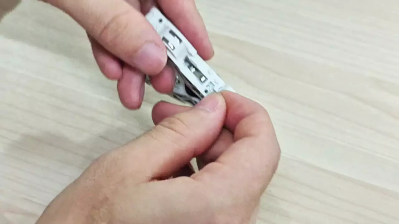
Press down the cutter handle to release filament tension.
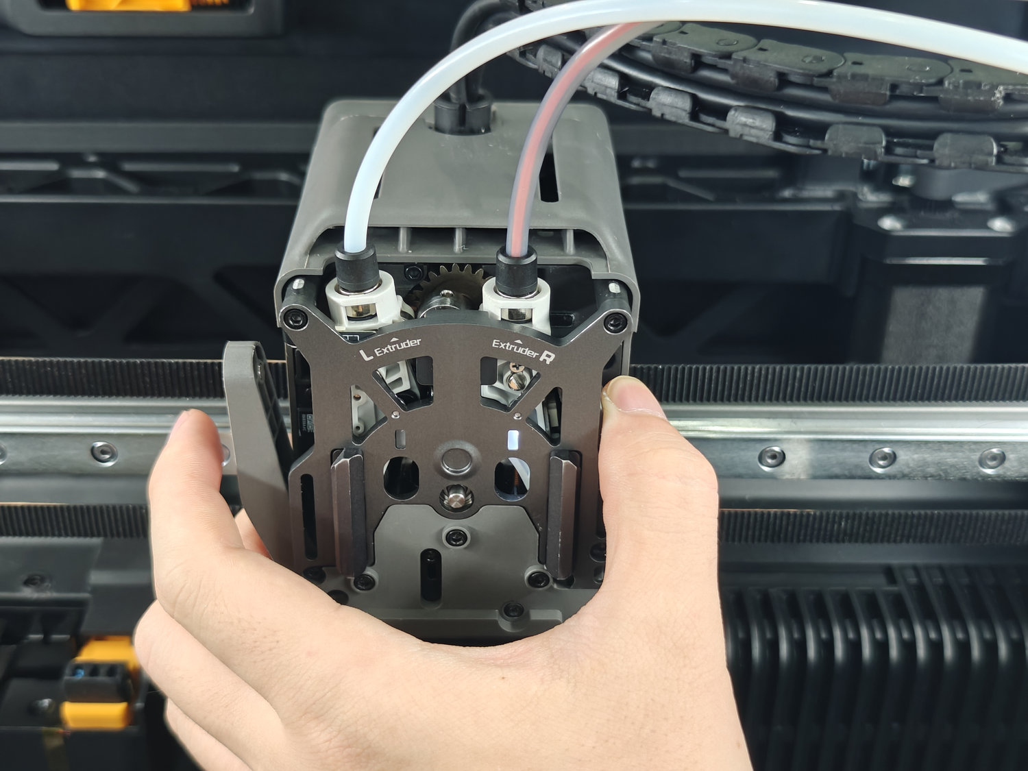
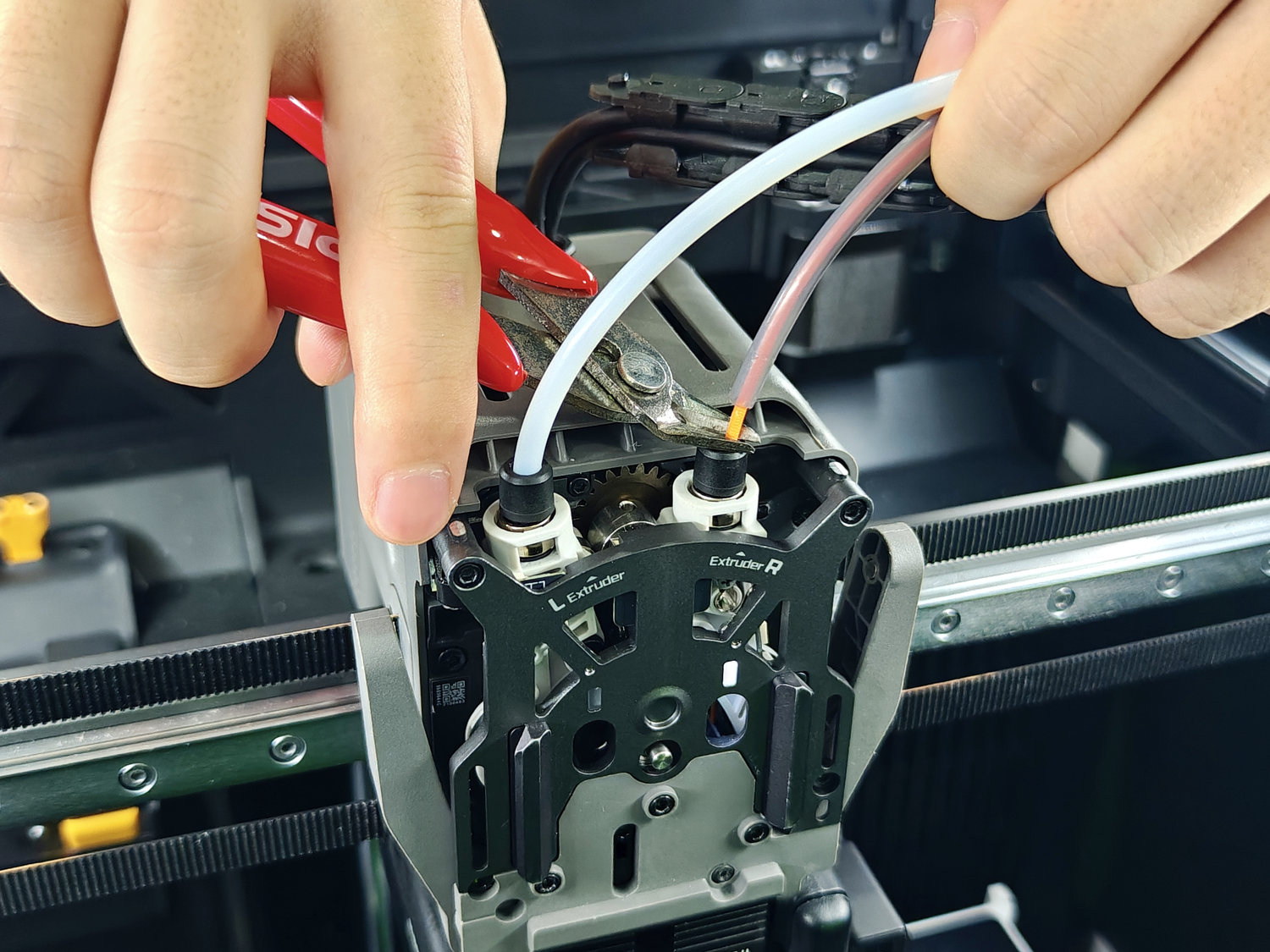
Push down the PTFE tube coupler to release the tube, then cut the filament to prevent resistance or tangling during the cleaning process.
Next, refer to the corresponding wiki to remove the extruder front cover.
¶ Preliminary Removal of Residual Waste Filament
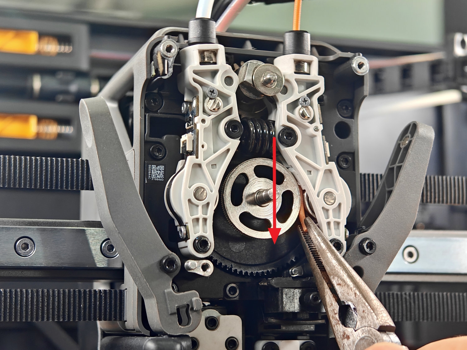
After removing the front cover, you can perform an initial cleanup of leftover filament by using needle-nose pliers to pull the filament straight downward.
If the leftover filament tail is too short or the initial cleaning attempt is unsuccessful, further disassembly of the idler assembly is required for thorough cleaning.
¶ Removing the Idler Assembly
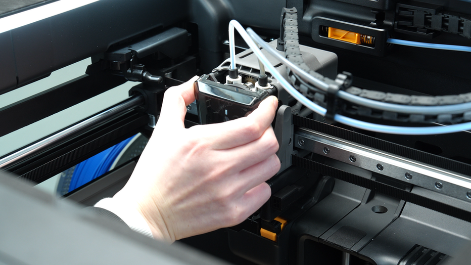
To completely clear internal residue, you need to remove the idler assembly from the toolhead. Please refer to the corresponding wiki to remove the idler assembly.
When removing the idler assembly, be sure to handle the internal ribbon cable with care. Avoid excessive pulling to prevent cable damage.
¶ Cleaning the Idler Assembly
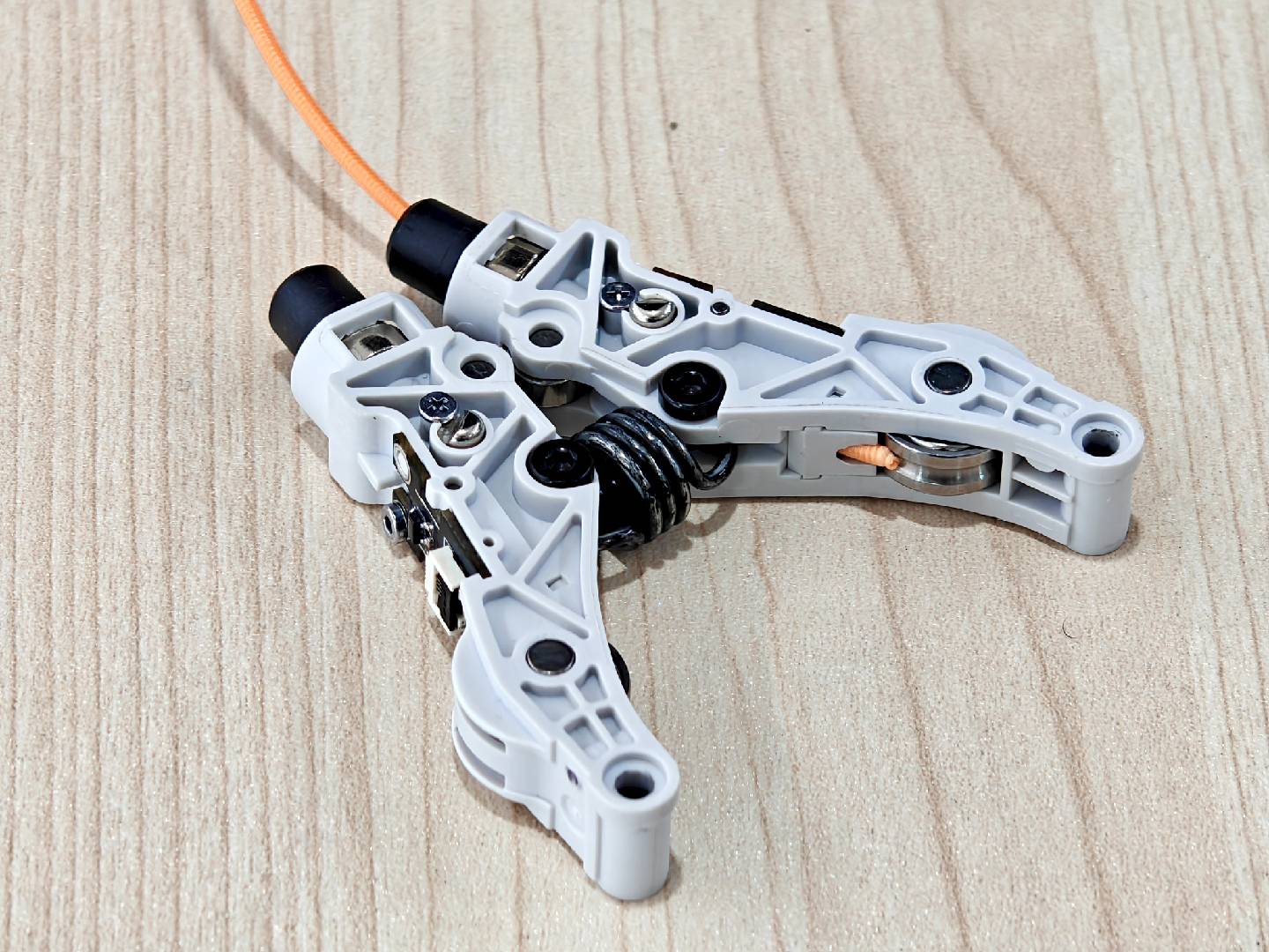
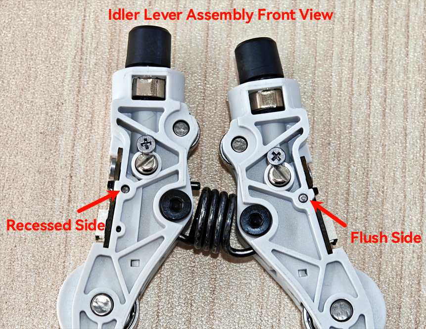
As shown in the image below, each side of the idler lever is equipped with a cylindrical pin: the left side features a recessed pin, while the right side has a flush pin.
Taking the left idler lever as an example.
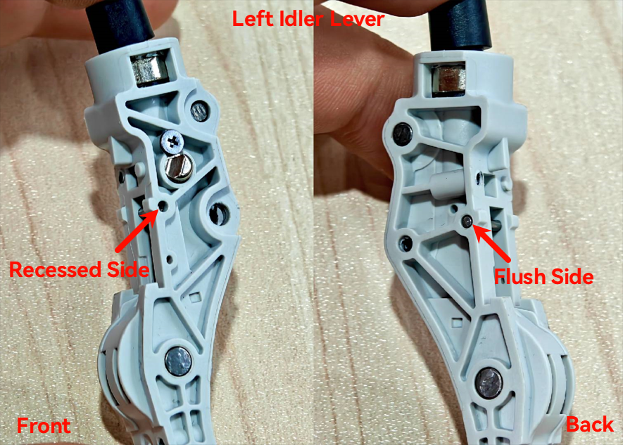
Use an H1.0 hex key (or an appropriately sized tool) to push out the cylindrical pin.
Note: The pin should be pushed out from the recessed side toward the flush side.
After pushing out the pin, you will notice that the pin on the flush side has a knurled surface, which is the key feature securing it to the idler lever.
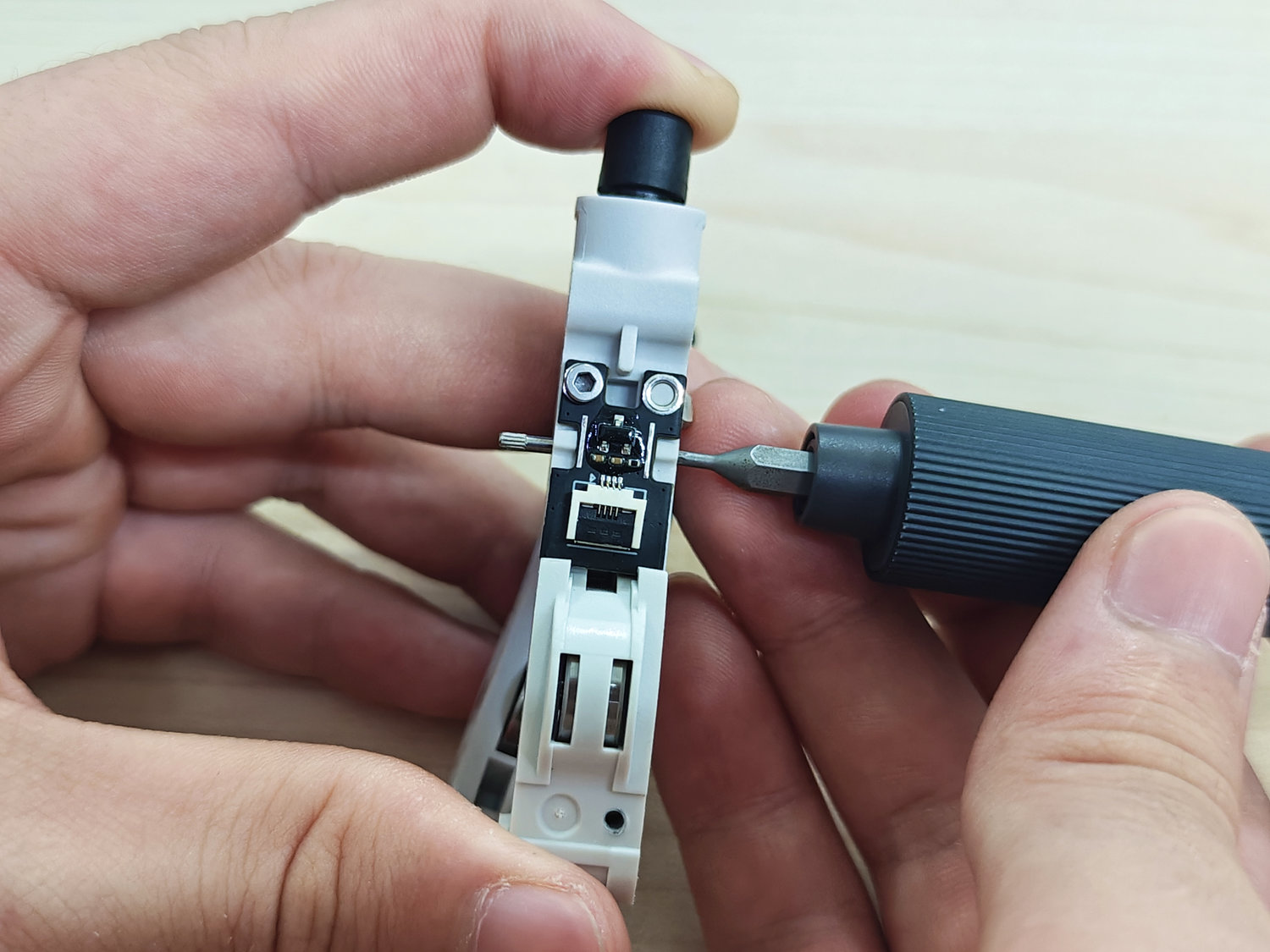
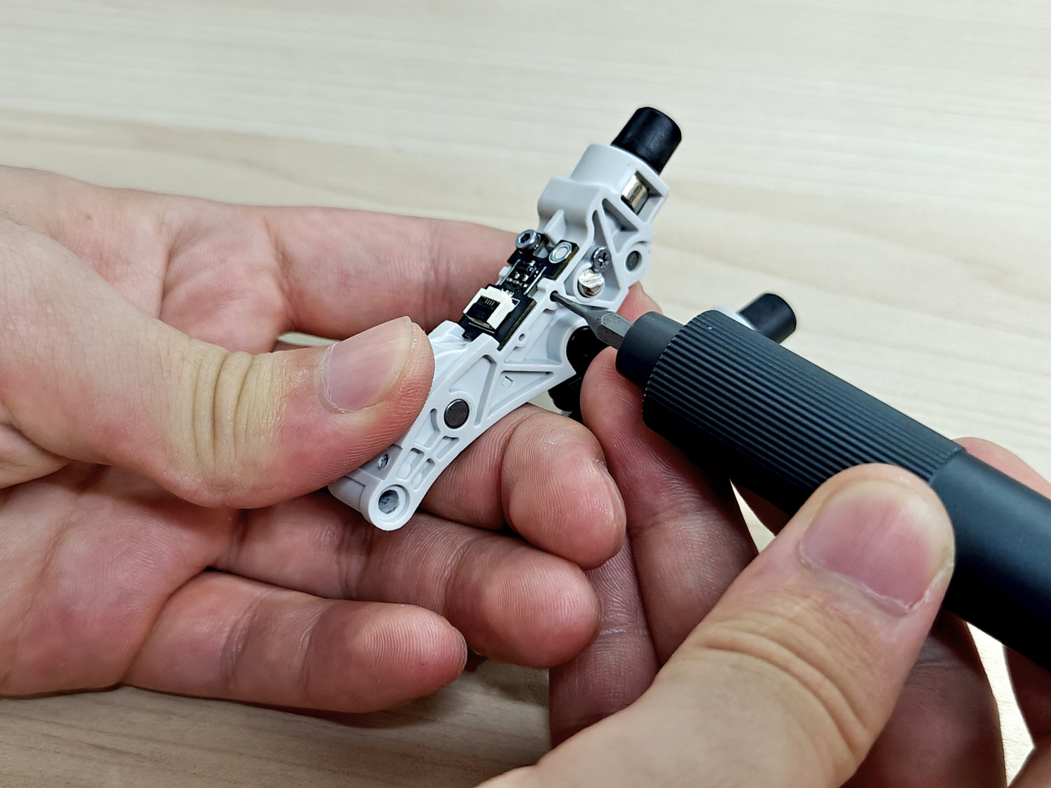
Unscrew the fixing screws of the Hall sensor board and carefully remove the board.
During removal, be sure to watch out for a torsion spring inside, which may pop out and get lost when the Hall sensor board is taken off.

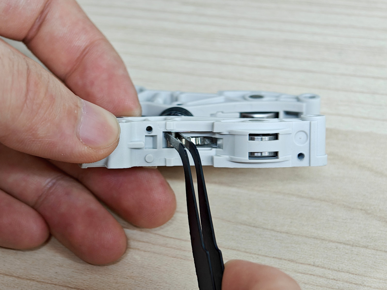
Carefully use tweezers to remove the torsion spring and rocker arm.
The entire idler lever assembly consists of the following components:
-
Idler lever body
-
Torsion spring
-
Rocker arm
-
Hall sensor board
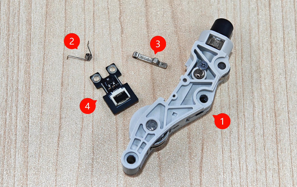
Note: The internal components are very small. Please handle them with care during disassembly and assembly to avoid losing any parts.
It is recommended to work on a clean, well-lit workspace and prepare a storage container to keep the removed components.
After removing all internal components, use an H1.5 hex key (or an appropriate cleaning tool) to pass through the side hole of the idler lever and thoroughly clear any remaining filament debris or blockages inside.
Ensure the passage is completely unobstructed.

¶ Installing the Idler Lever Assembly
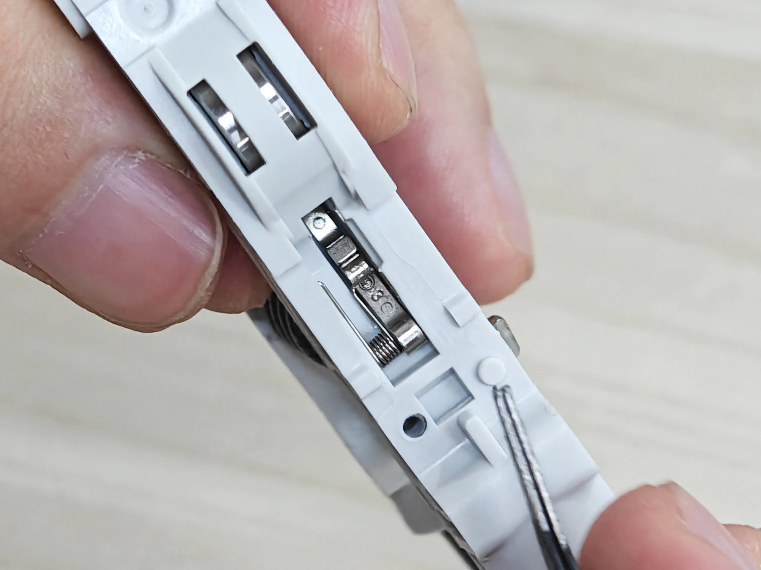
First, correctly position the rocker arm into the corresponding slot on the idler lever body.
Next, install the torsion spring by inserting its longer end into the small slot on the left side of the idler lever.
Once the left side is secured in the hole, carefully rotate the right end of the spring so that it applies pressure on the rocker arm.
Use tweezers to gently adjust the positions of the spring and the rocker arm to ensure they are properly engaged.
This step requires patience and precision due to the small size and elasticity of the components.
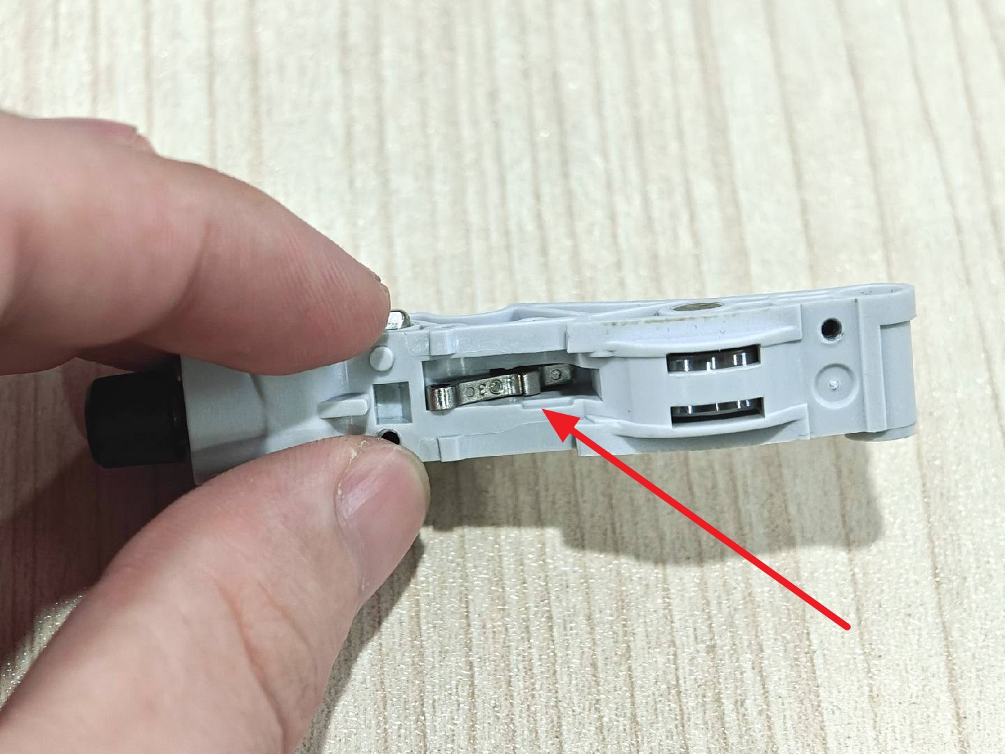
The image below shows the correct installation of the torsion spring and rocker arm.
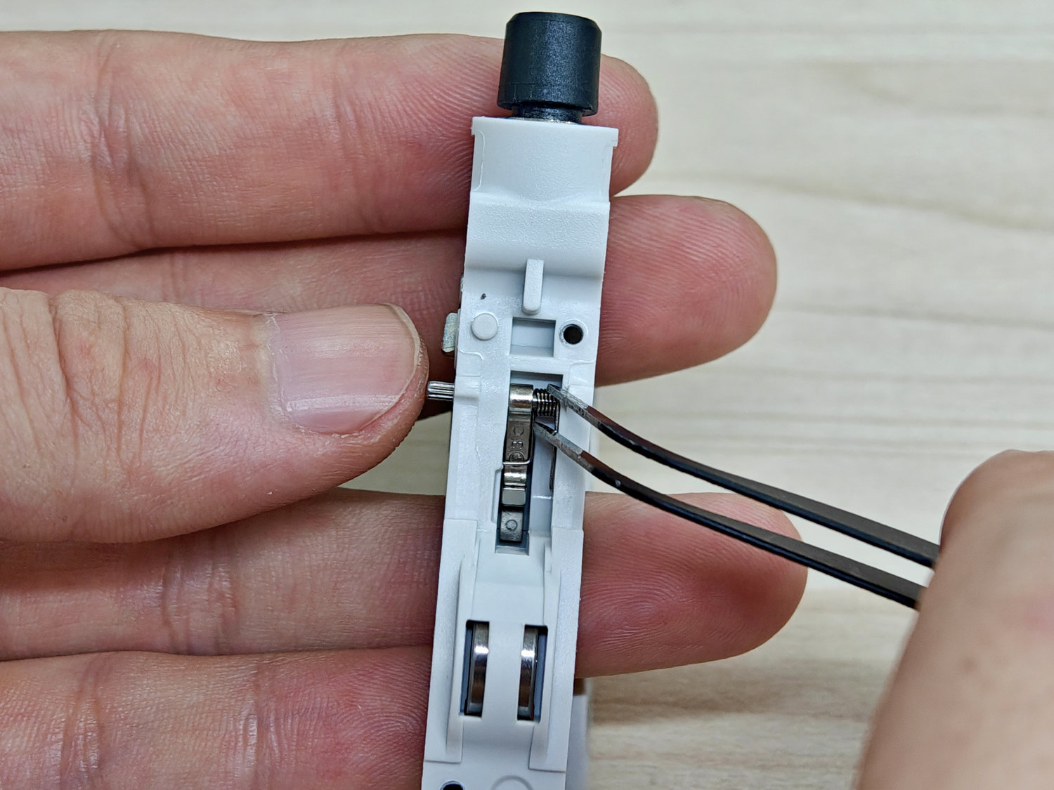
Reinsert the cylindrical pin to secure the rocker arm and torsion spring.
When inserting the pin, you can use tweezers to gently hold the torsion spring in place to prevent it from snapping out.
Note the insertion direction: Insert the smooth end first, then push inward until the pin is flush with the surface of the idler lever.
Finally, reinstall the Hall sensor board and tighten the fixing screw.
¶ Installing the Idler Assembly
After reassembling the idler lever assembly, reinstall it back onto the toolhead.
Please refer to the corresponding wiki to install the idler assembly.
¶ Installing the Extruder Front Cover
The final step is to reinstall the extruder front cover.
Please refer to the corresponding wiki to install the extruder front cover.
¶ Functional Testing
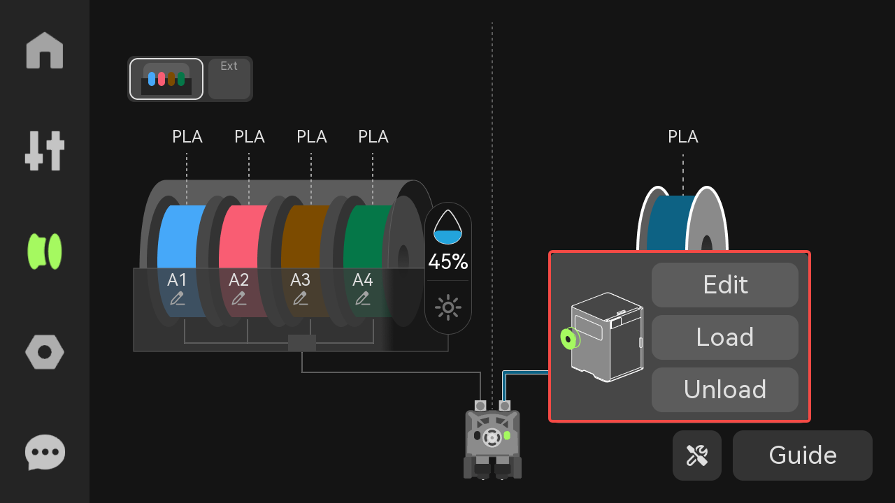
On the printer’s touchscreen or control interface, select the "Feed" option and observe whether the nozzle extrudes filament normally.
If the filament flows smoothly without any abnormalities, the repair is considered successful.
¶ End Notes
We hope the detailed guide provided has been helpful and informative.
If this guide does not solve your problem, please submit a technical ticket, we will answer your questions and provide assistance.
If you have any suggestions or feedback on this Wiki, please leave a message in the comment area. Thank you for your support and attention!