¶ Important!
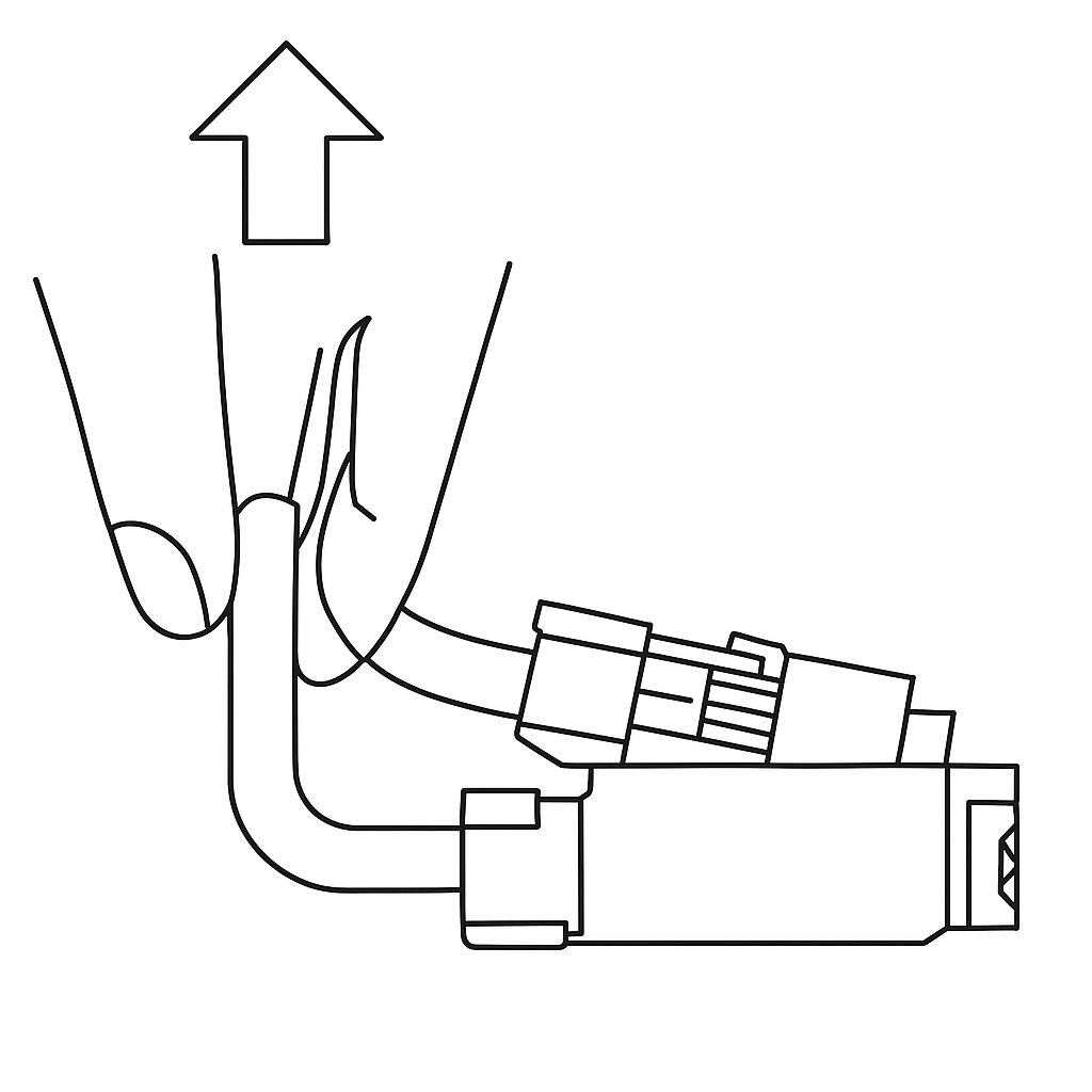
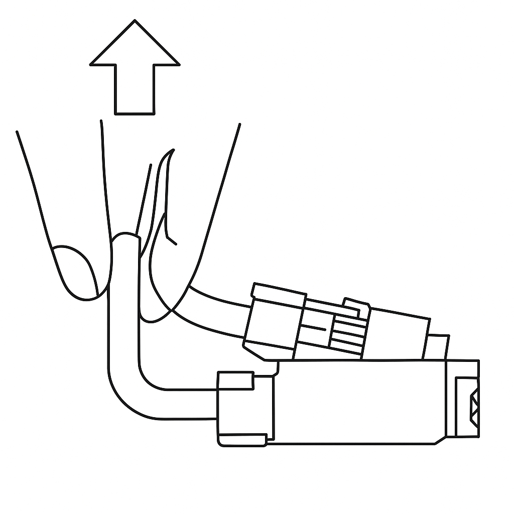
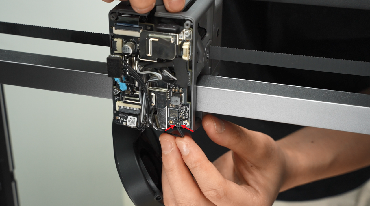
The H2S extrusion main board uses a small plug for the eddy current coil. When unplugging it, always lift the plug straight up, perpendicular to the board, and avoid pulling or twisting it sideways. This prevents damage to both the plug and the circuit board.
¶ Eddy Current Coil
The eddy current coil is mounted on the extruder above the hot end. Once installed correctly, the gap between the coil and the hot end heatsink should be between 0.15 mm and 0.5 mm.
Parts included:
- 1 × Eddy current coil
- 2 × M2×6.5 screws
¶ When to replace
- Eddy current coil damaged;
- Confirmed by Bambu Lab's official technical support that the eddy current coil needs to be replaced.
¶ Tools and Materials Needed
- H2S Eddy current coil
- H1.5 Hex Wrench
- 25 minutes
¶ Screw list
The following screws will be removed during the operation.
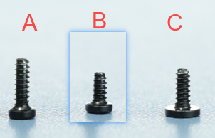
- Screw A: 3 screws for the back of the component cooling fan (shared with the back cover) and the tool head back cover; plus 2 screws for the eddy current coil (BT2×6.5).
- Screw B: 2 screws for the hot-end fan (BT2×4).
- Screw C: 2 screws on the left and right sides of the component cooling fan (BT2×5).
Safety Warning
Important Reminder!
Before performing any maintenance work, be sure to turn off the power of the printer, including maintenance on the printer's electronic components and tool head wires. Performing such operations while the printer is powered on may cause a short circuit, which can damage electronic devices and pose a safety hazard.
During maintenance or troubleshooting, you may need to disassemble components such as the hot end, thereby exposing wires and electronic components. If they come into contact with each other or with other metals or electronic components while the printer is still powered on, a short circuit may occur. This will damage the printer's electronic components and cause other problems.
Therefore, before performing any maintenance, be sure to turn off the printer and disconnect the power supply to prevent short circuits or damage to the printer's electronic components, thereby ensuring that maintenance work is carried out safely and effectively. If you have any questions about this guide, please click here to submit a ticket, and we will respond promptly and provide assistance.
¶ Remove the eddy current coil
¶ Step 1: Loosen the Part Cooling Fan
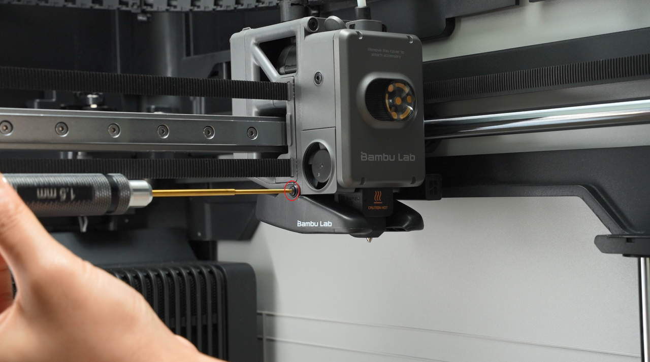
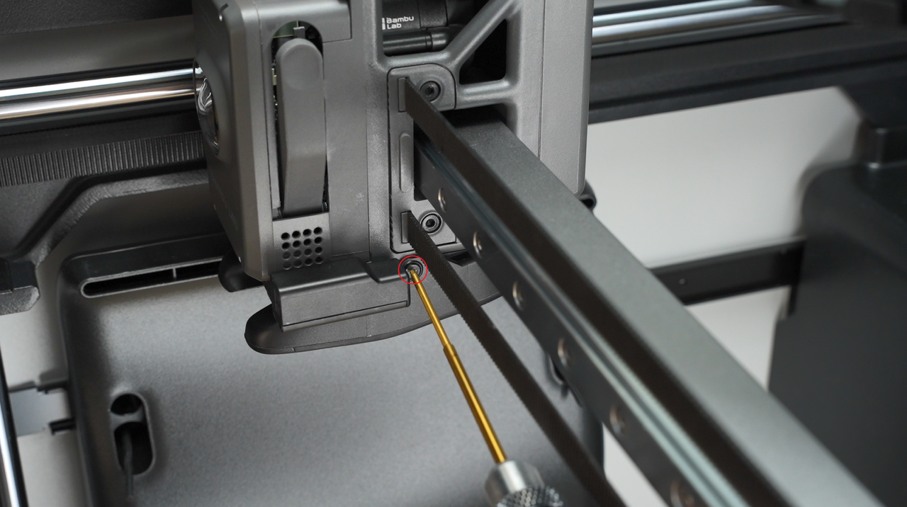
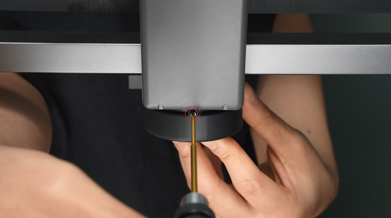
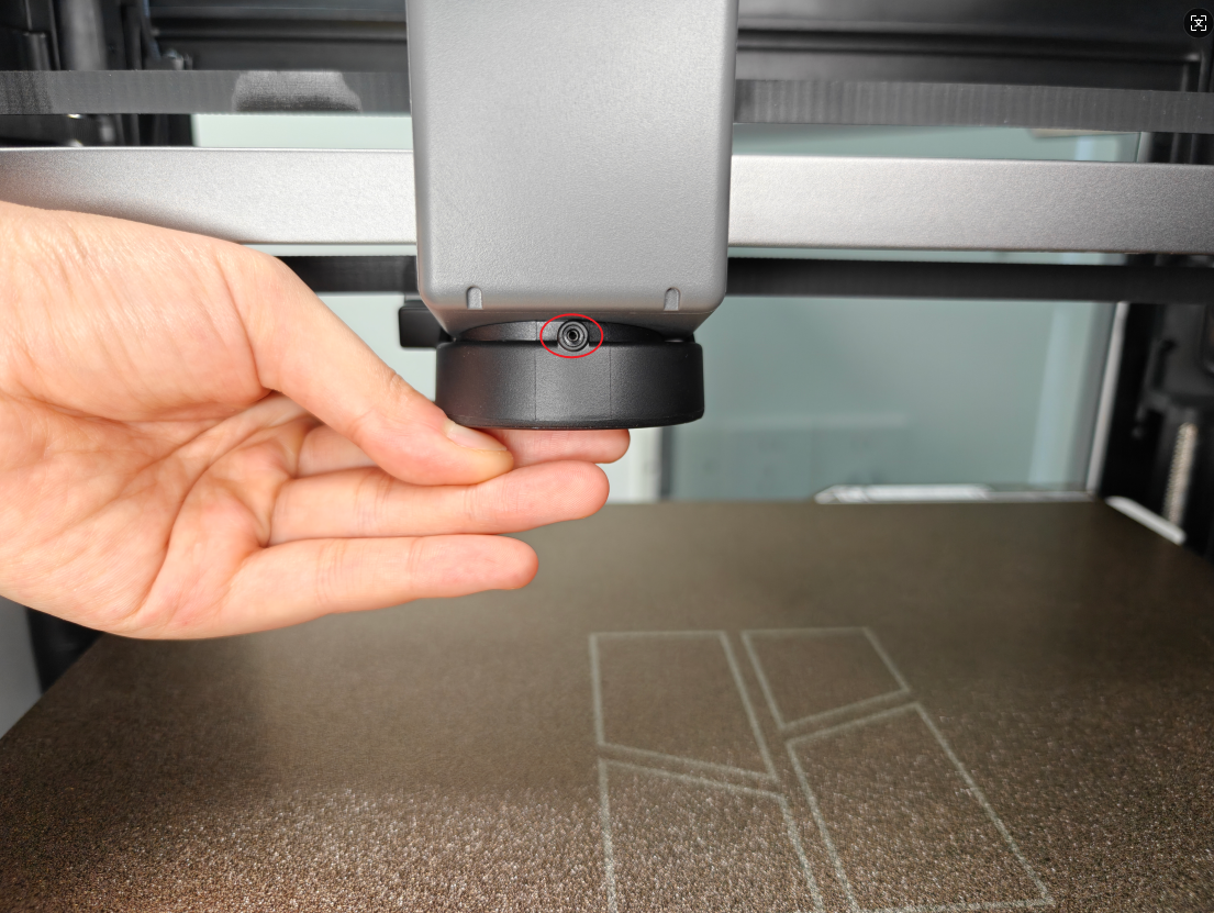
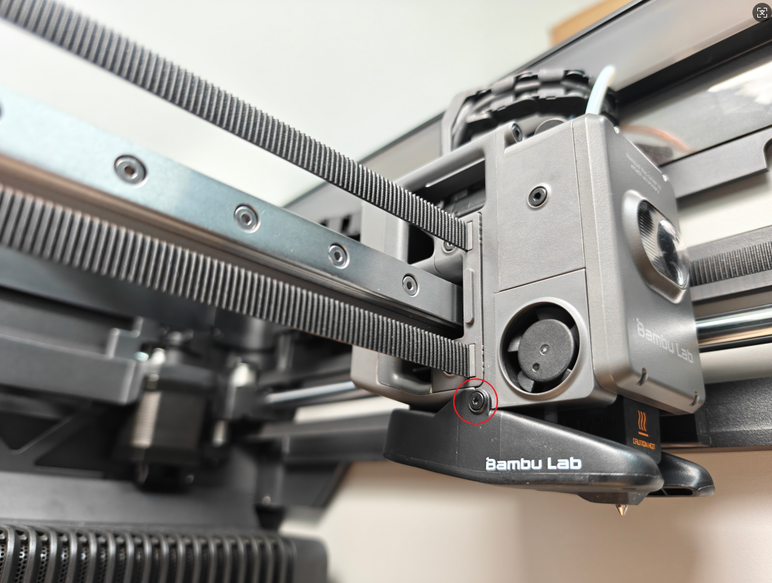
Remove the 3 screws holding the part cooling fan: one on the left, one on the right, and one on the back that is shared with the tool head rear cover.
 |
 |
|---|
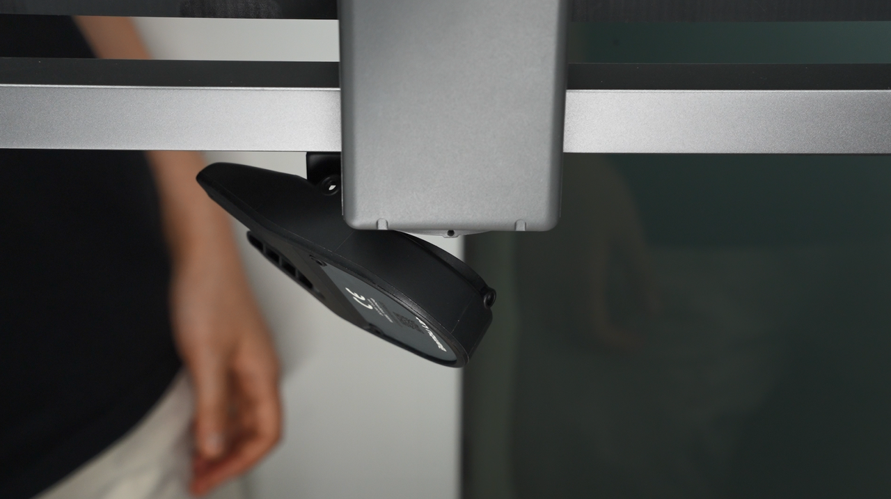
After loosening the screws, the fan will hang down. Do not pull on it, as this could damage the connector.
¶ Step 2: Remove the rear cover of the toolhead
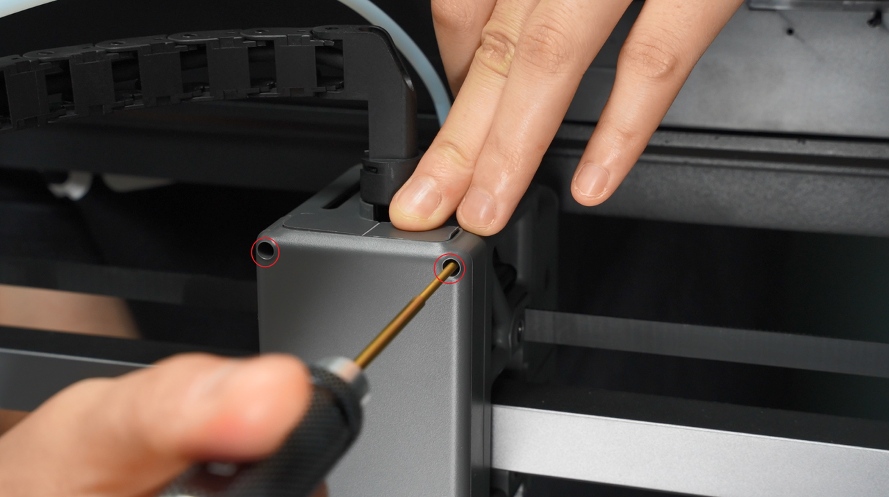
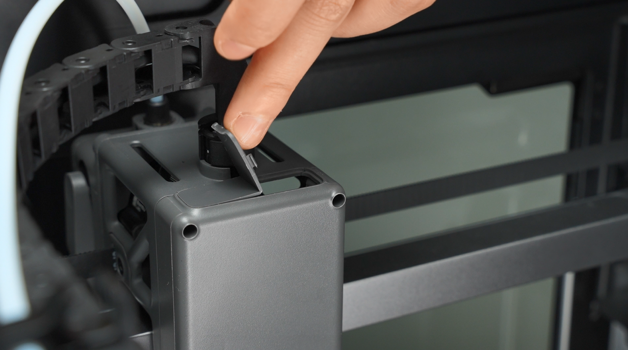
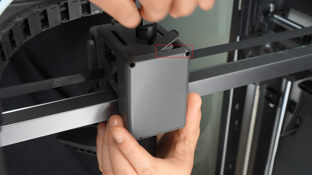
Remove the two screws above the rear cover of the toolhead, then lift open the module interface cover.
 |
 |
|---|
After opening the interface cover, gently push the toolhead rear cover backward by pressing lightly from the inside with your finger.
 |
 |
|---|
¶ Step 3: Disconnect the eddy current coil connector from the tool head board
Carefully tear off the acetate tape on the eddy current coil plug.
Note: Keep the tape safe, as it needs to be reattached during installation.
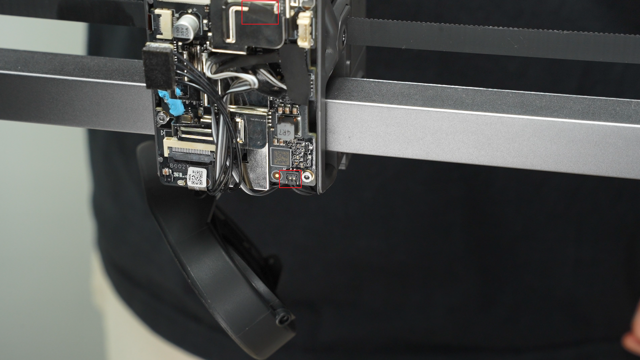
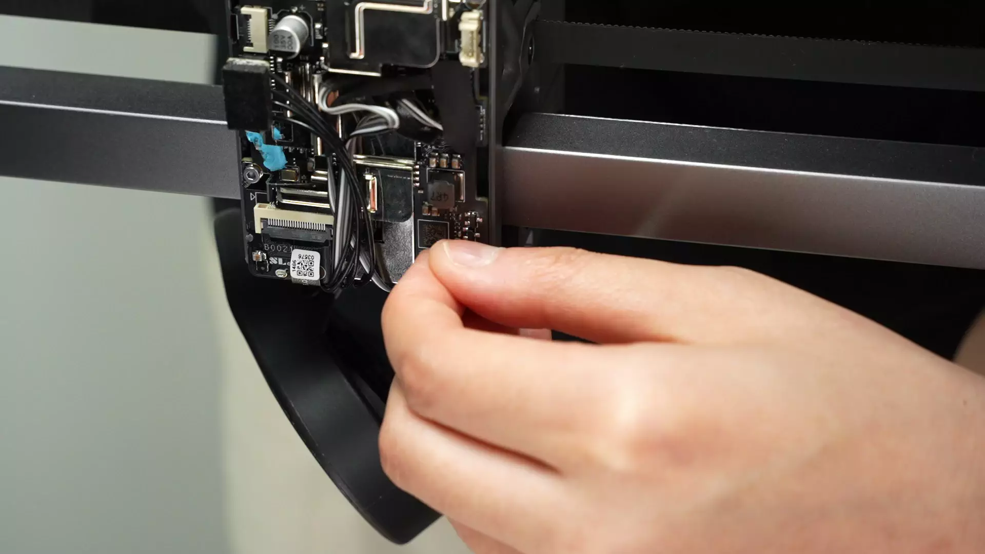
Pinch the base of the plug and apply force in a direction perpendicular to the PBC board to disconnect the eddy current coil plug.
¶ Step 4: Remove the hotend
The next step requires the removal of the hotend. Please refer to this H2S Hotend Removal tutorial to remove it, then move to the next step.
¶ Step 5: Remove the hotend fan and eddy current coil
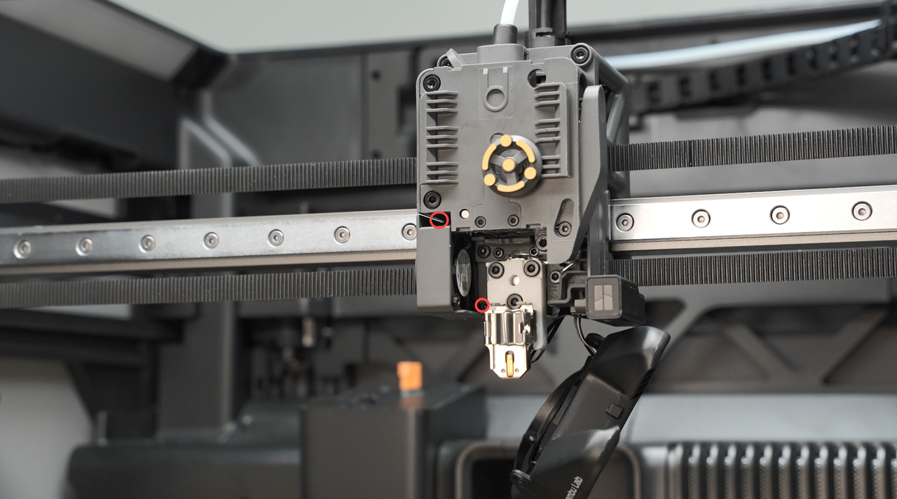
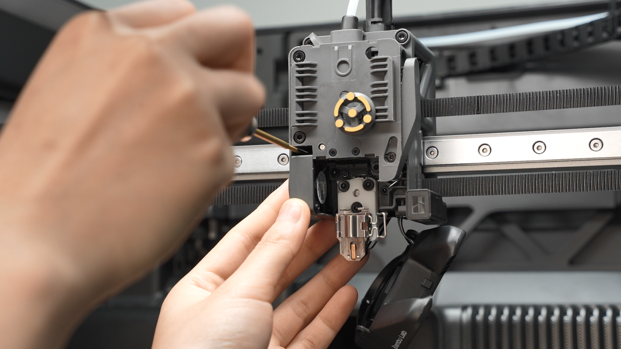
After removing the hotend, unscrew the two hotend fan screws and take out the fan. This step is required only to create more room to work.
Note: You can leave the fan plug connected to the tool head board and only loosen the screws to free the two cables.
 |
 |
|---|
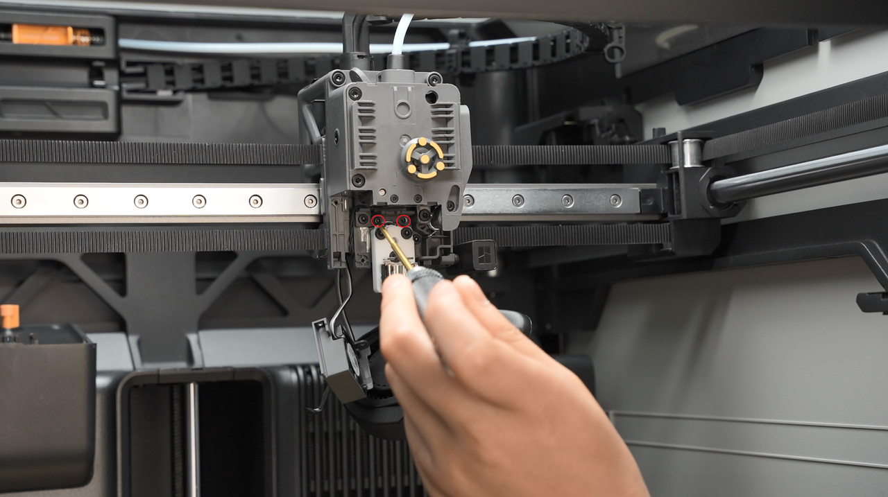
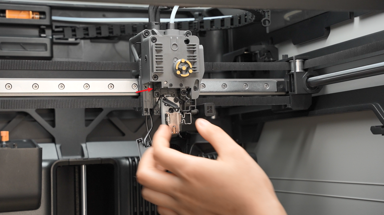
Remove the two screws holding the eddy current coil, and carefully bypass the wiring as shown by the red arrow.
 |
 |
|---|
The wires run under the tool head through wire management clips.
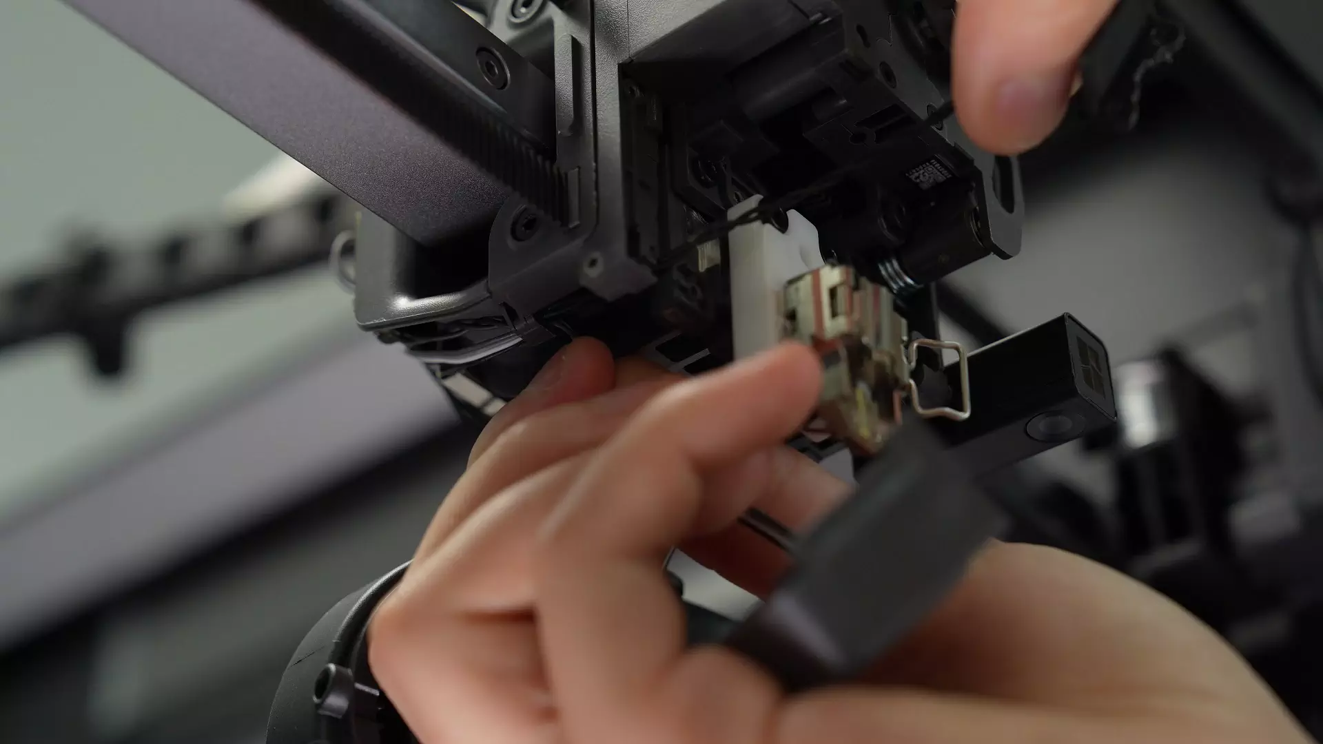
Remove the hot-end fan and eddy current coil wires from the cable trough in order, then take out the old eddy current coil, as shown in the video below.
¶ Install the new eddy current coil
¶ Step 1: Install the new eddy current coil and hot end fan
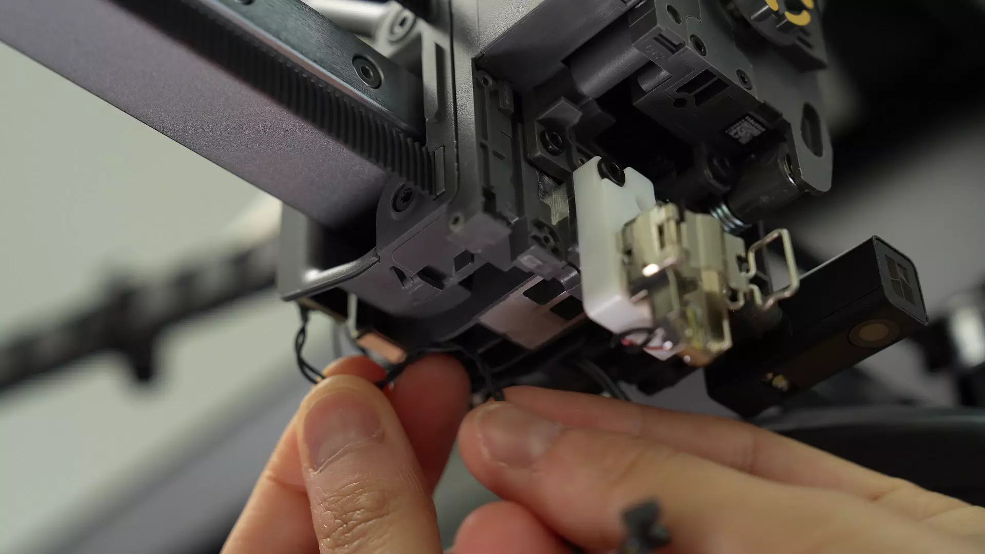
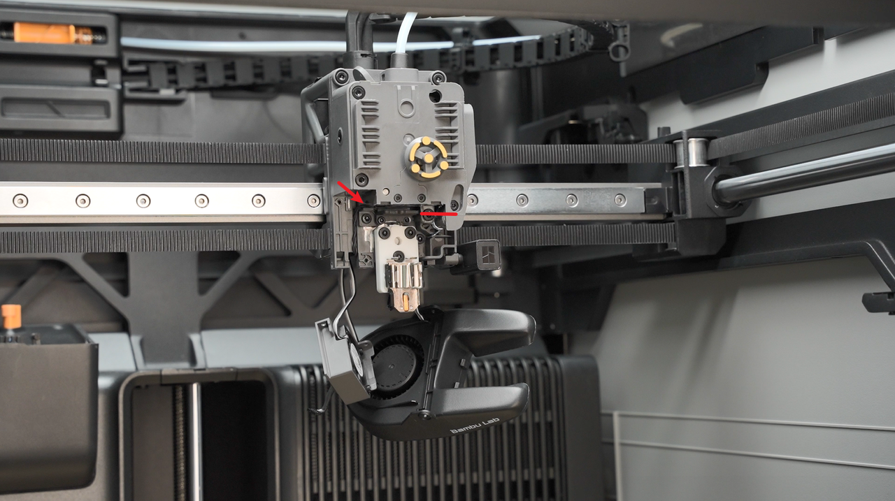
Insert the wires for the eddy current coil and hot-end fan into the cable management slot, following the sequence shown in the video.
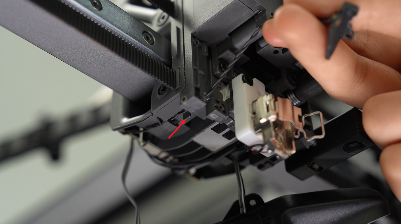
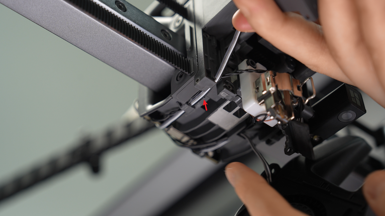
Important: When routing the cable from front to back, make sure it passes to the left of the wire post as indicated by the arrow.
 |
 |
|---|
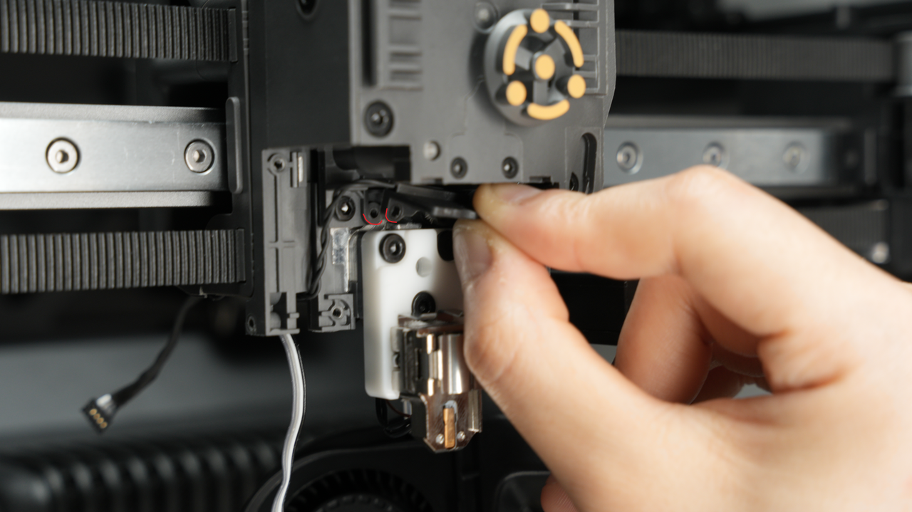
Line up the screw holes and make sure the curves of the two parts match. Insert the screws, pre-tighten one first, then the other, and finally tighten the first screw again. This ensures the eddy current coil sits level and horizontal after installation which is crucial for normal operation.
 |
 |
|---|
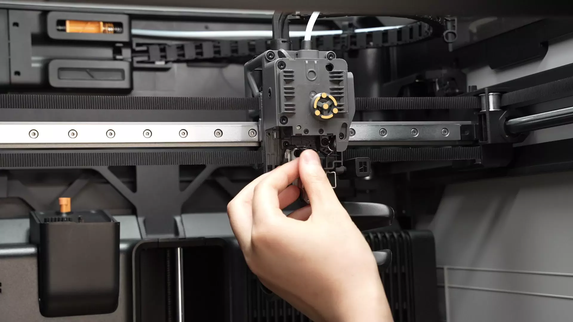
The steps for this operation are shown in the video below.
¶ Step 2: Calibrate the eddy current coil position (important)
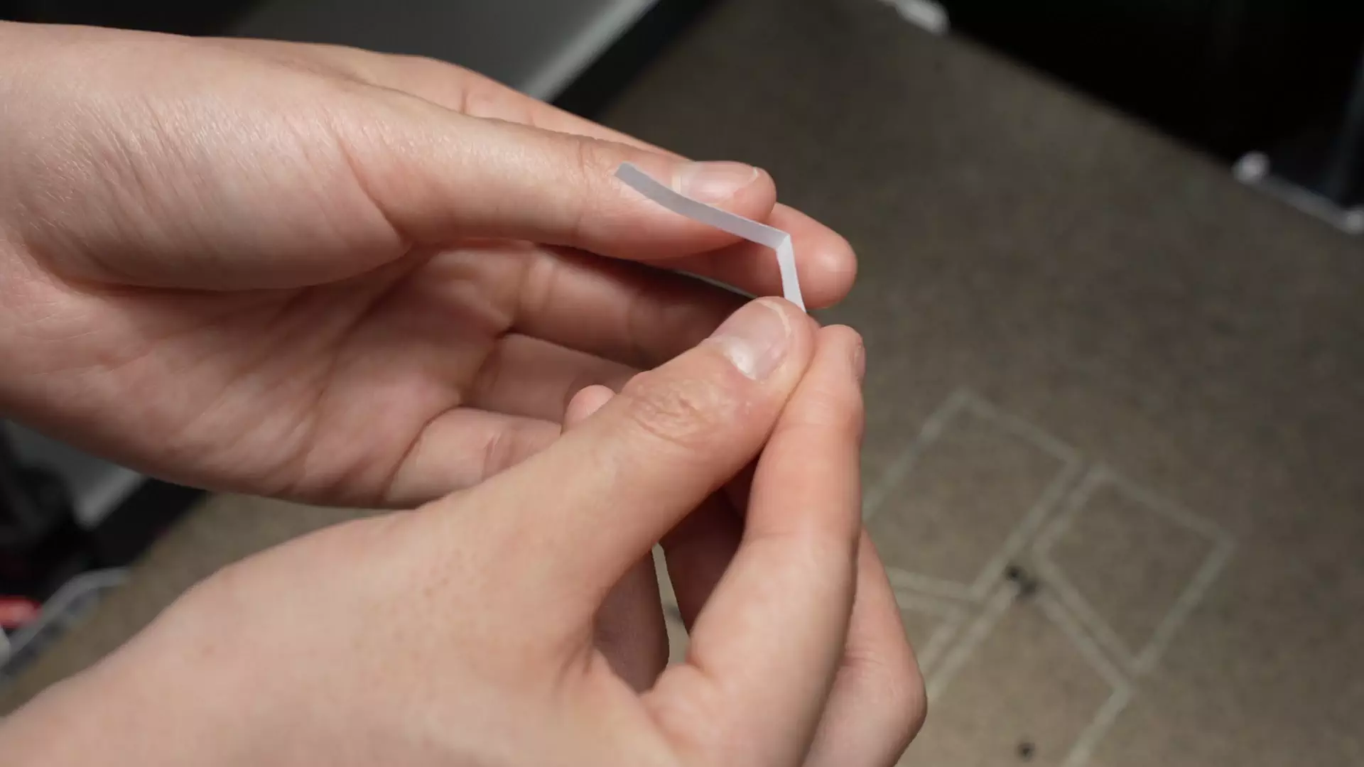
After reinstalling the hot end, fold a piece of paper in half and slide it into the gap between the hot end and the eddy current coil. You should feel slight friction, but the paper should still move freely. This indicates the gap is roughly 0.2–0.3 mm, which is the correct spacing.
¶ Step 3: Install the hotend fan
Position the fan so that the labeled side faces the hot end and align it with the screw holes (see the red and yellow circles in the figure).
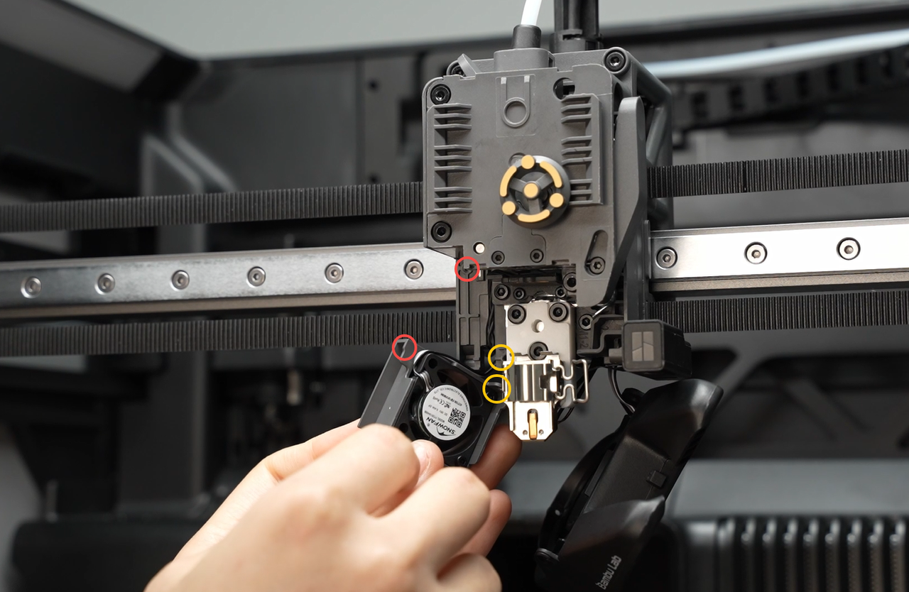
Fold the fan cable into the groove shown in the illustration, then install the fan.
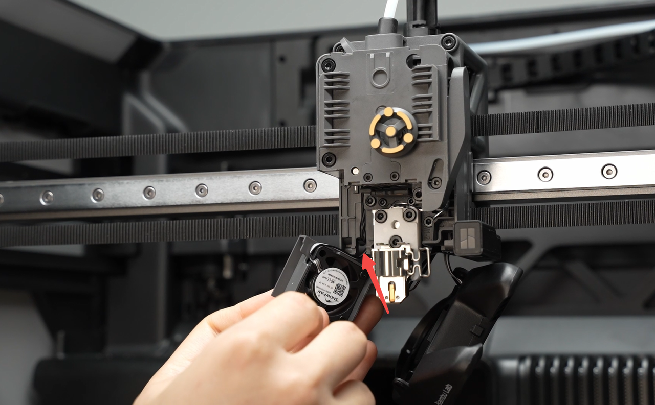
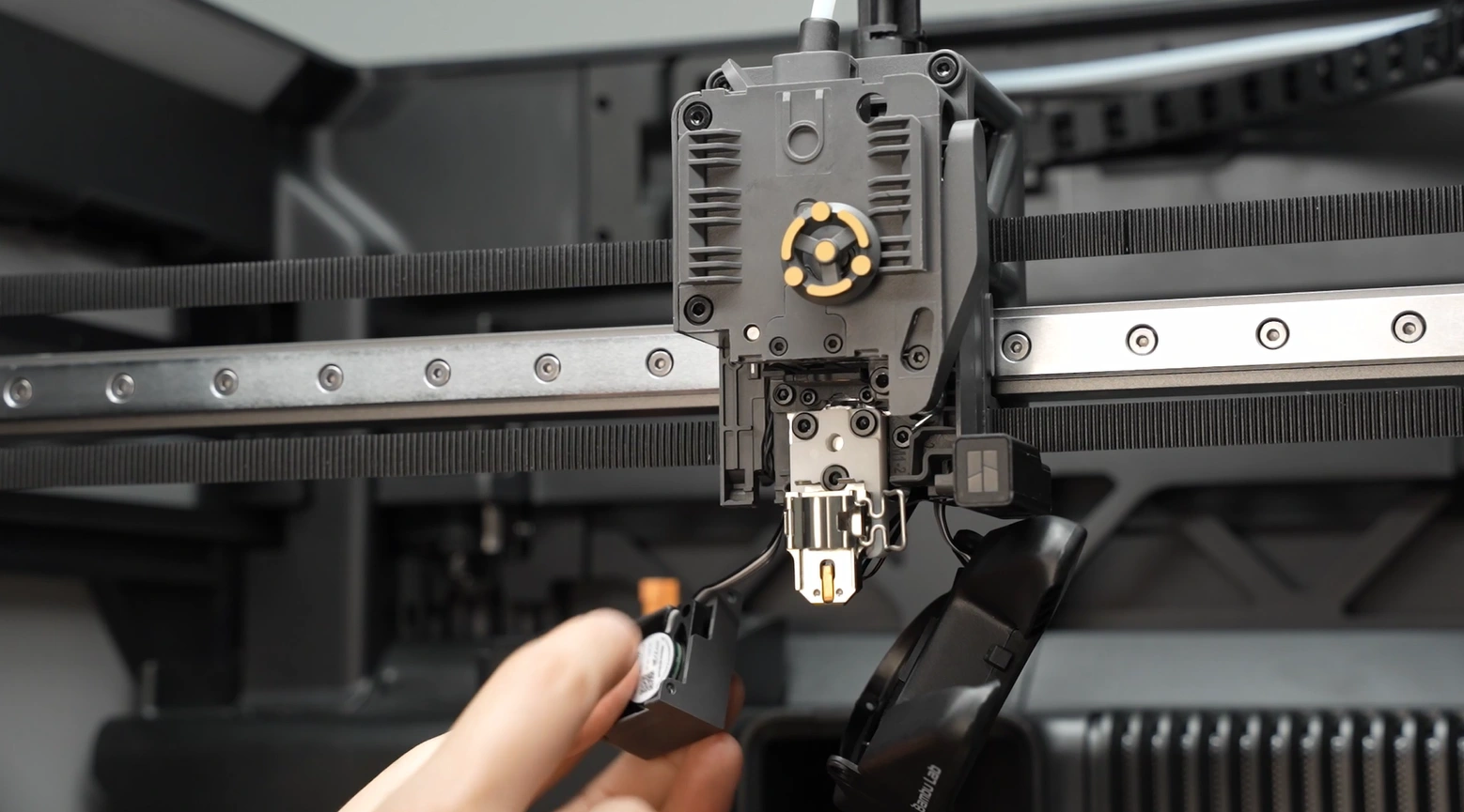
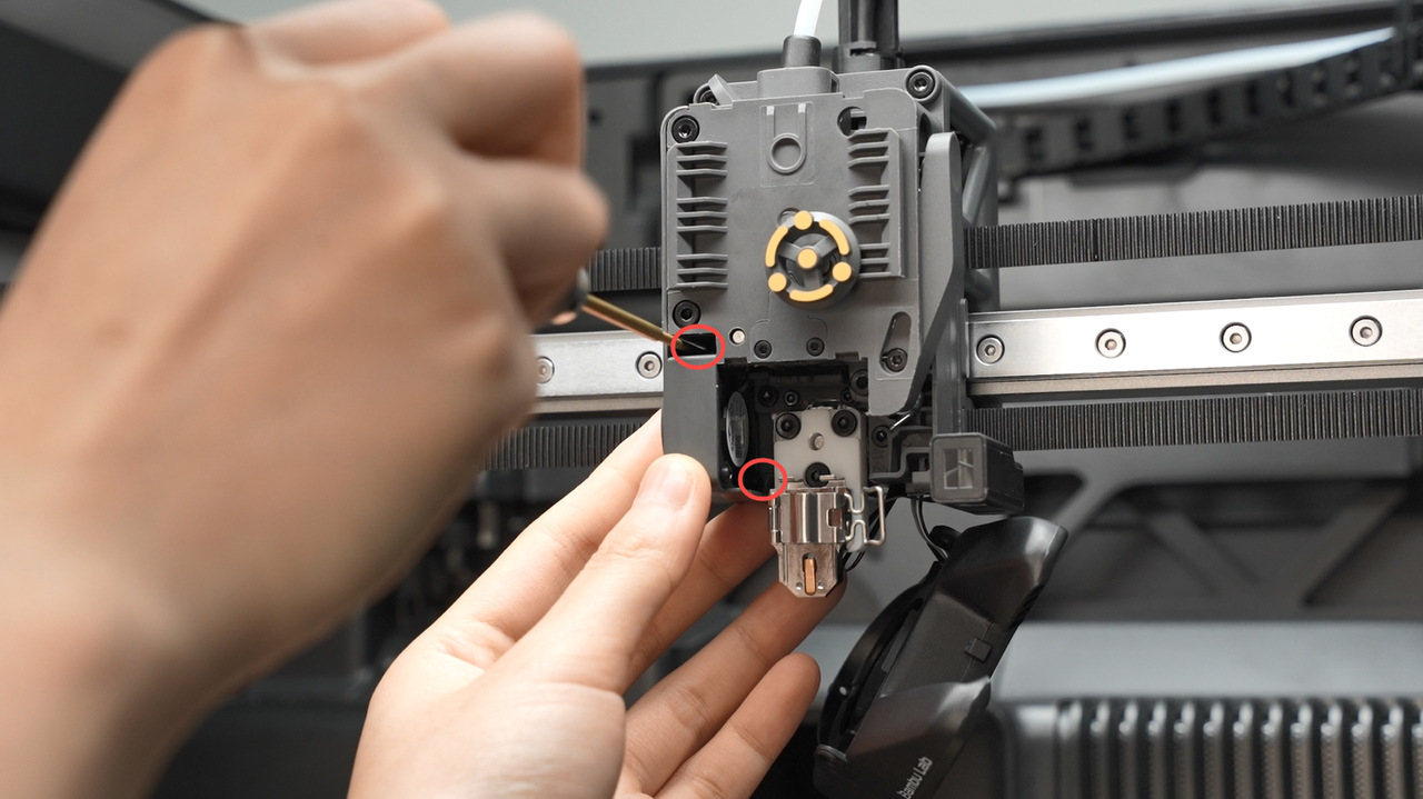
Secure the fan with the two screws shown below.
¶ Step 4: Install the hot end
he next step requires the installation of the hotend. Please refer to this H2S Hotend Installation tutorial to install it, then move to the next step.
¶ Step 5: Connect the eddy current coil connector on the TH board
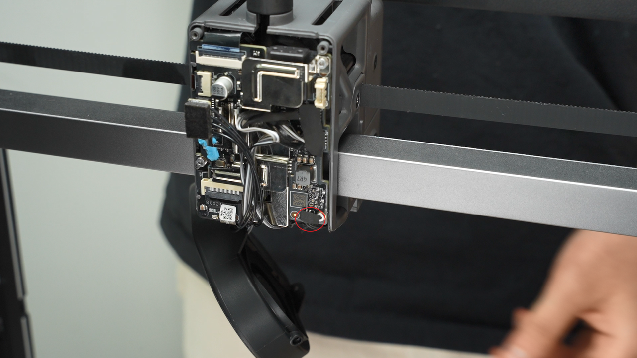
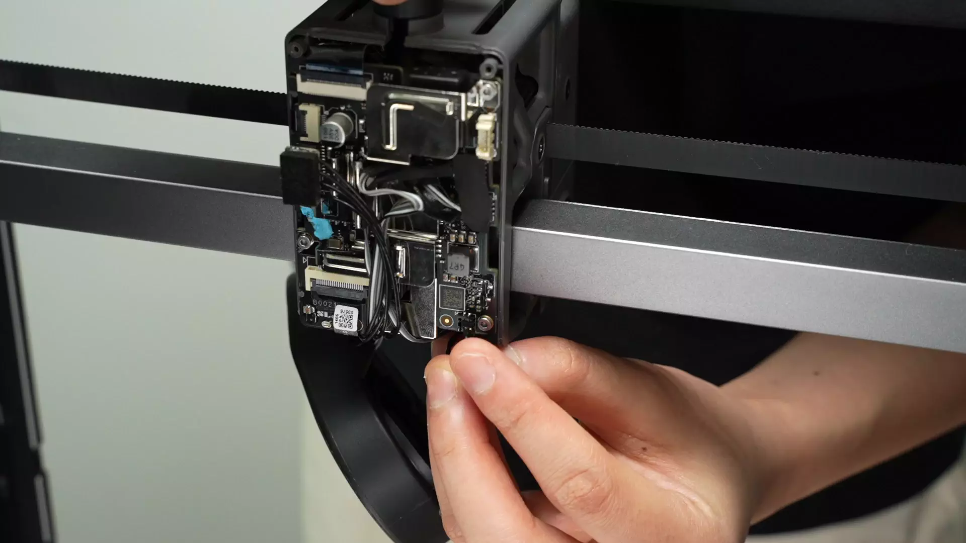
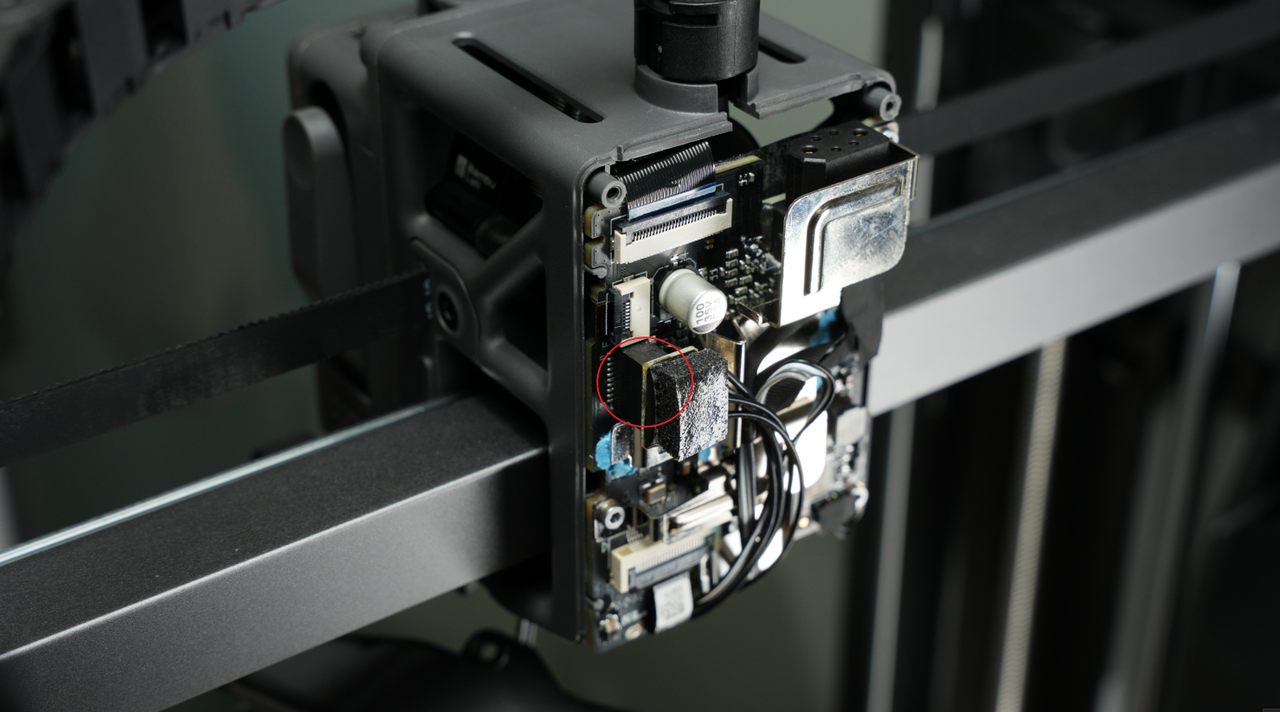
Align the plug with the socket on the tool head board, making sure the metal contacts face the back of the chassis. Press the plug in fully, and tuck any extra cable neatly under the tool head board.
Reapply the acetate tape previously removed, to cover the connector.
The procedure is shown below:
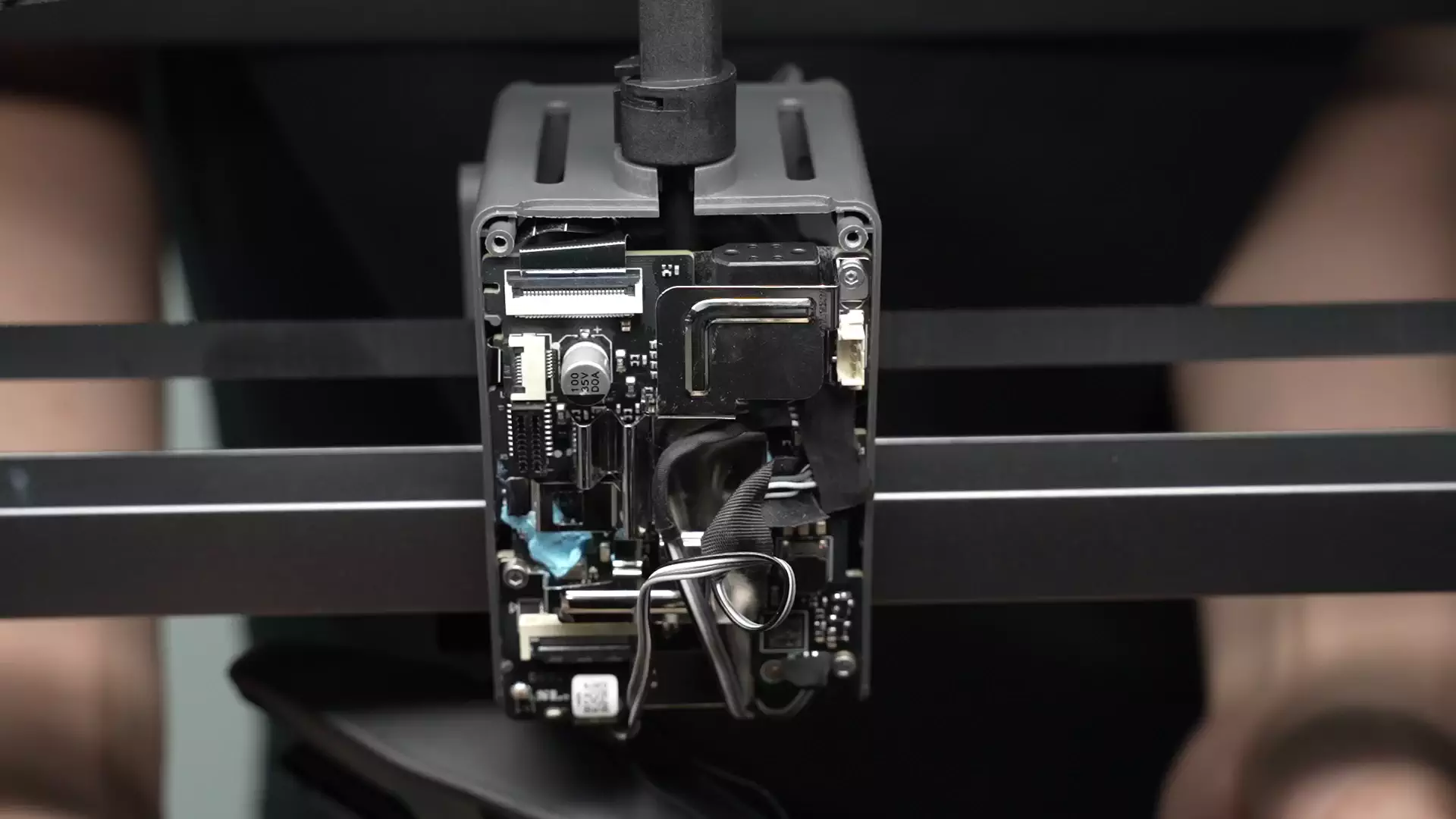
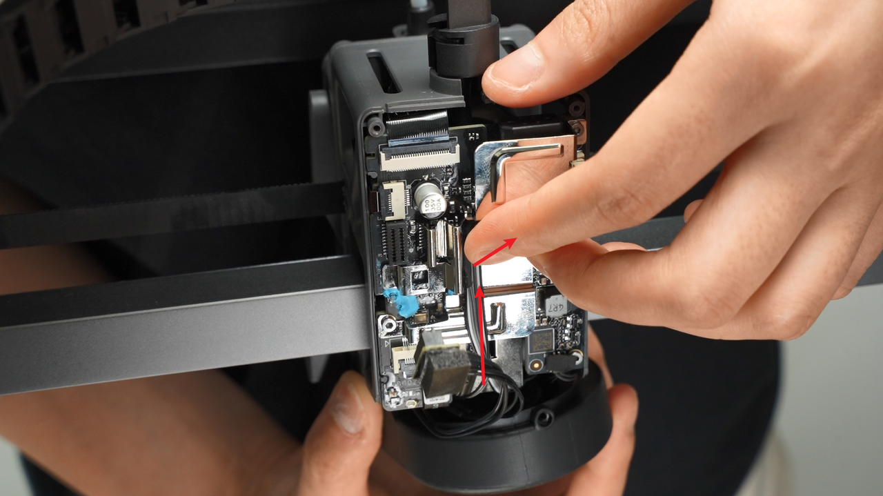
Pre-align the fan screw holes and position the fan cable on the tool head. Pull the cable upward and fold any excess so it won’t get pinched by the fan housing or rear cover, preventing fan malfunctions.
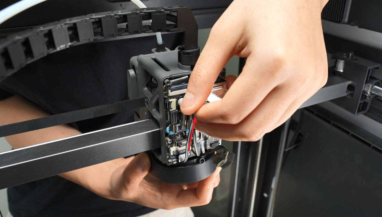 |
 |
|---|
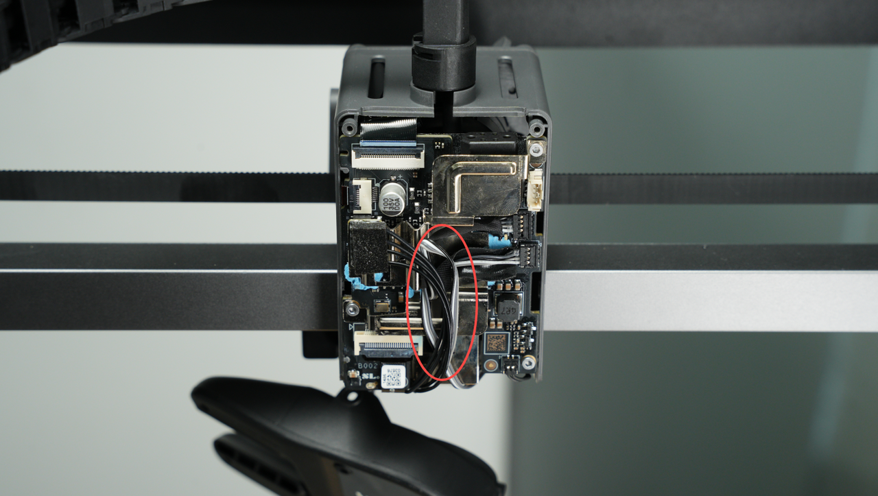
After organizing the cables, connect the hot end heating assembly plug and use its plug and cables to secure the component cooling fan cable in place.
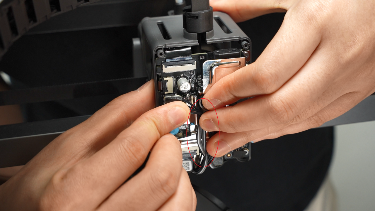 |
 |
|---|
When installing the hot end heating assembly, make sure it lines up with the screw holes to avoid misalignment.
¶ Step 6: Install the rear cover of the tool head
Install the rear cover of the tool head by pressing it back in position.
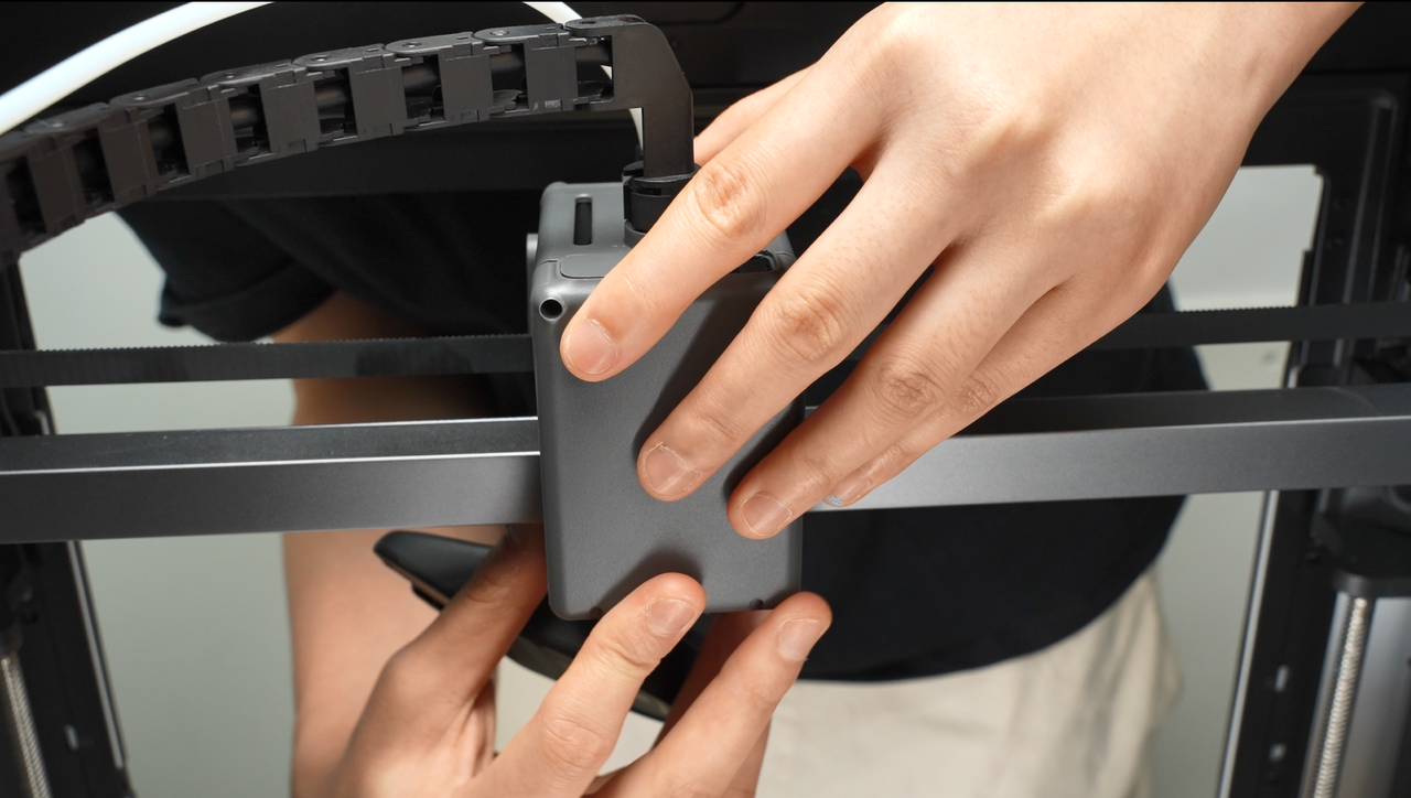
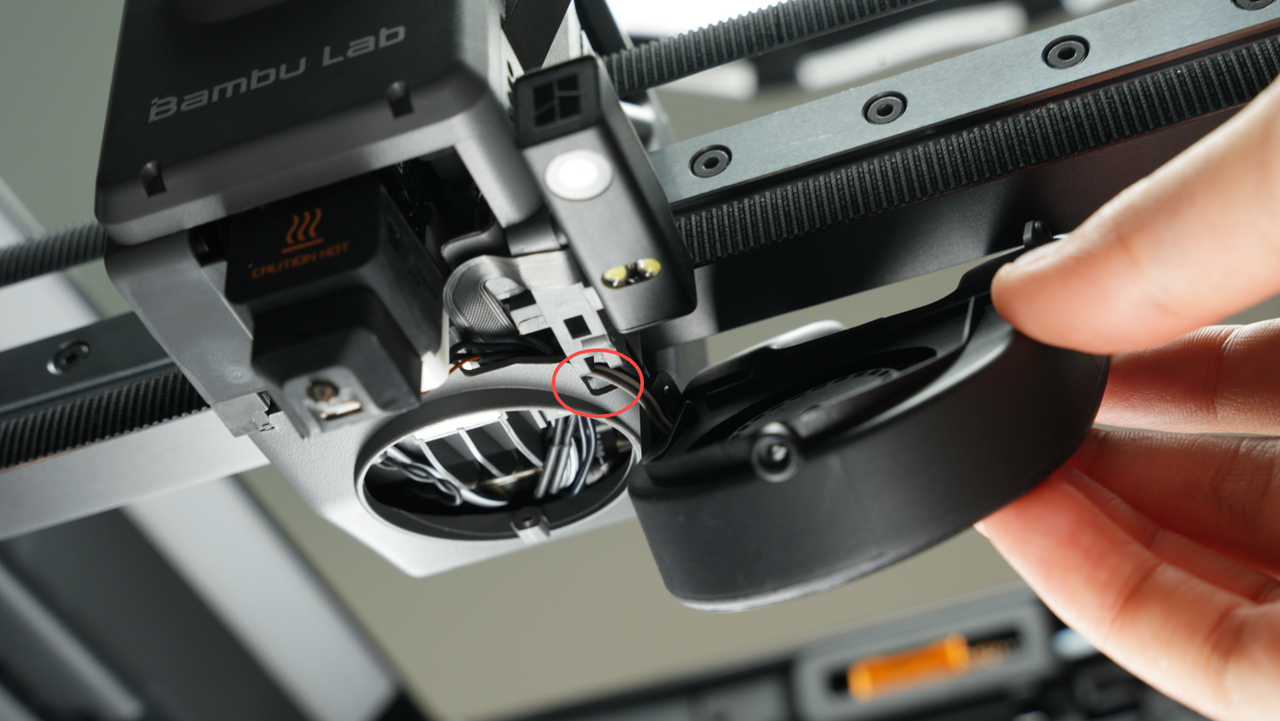
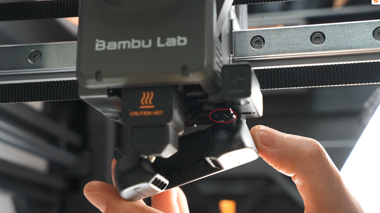
After installing, make sure the part cooling fan cable sits in its dedicated notch so it doesn’t get pinched by the rear cover frame.
 |
 |
|---|
Tighten the two screws from the rear cover.
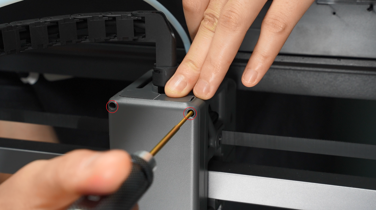
¶ Step 7: Install the part cooling fan
Align the fan with the screw holes and install it, taking care not to press on the fan cables. If the cable is too long, go back to Step 1 and fold the excess cable before proceeding.
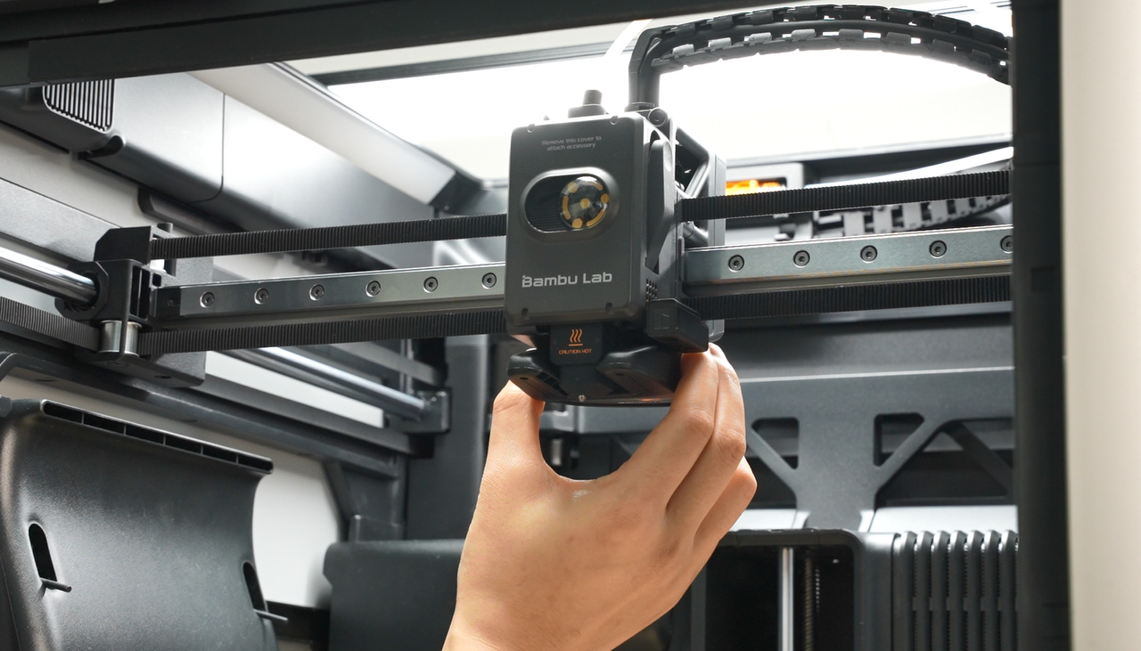
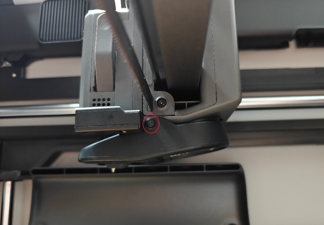
Tighten the three screws to securely fasten the part cooling fan.
 |
 |
|---|
 |
|---|
¶ Test the new eddy current sensor
Turn on the printer and run a homing and leveling operation. If no errors appear, it means the installation was successful and everything is working correctly.
Calibration after installation
¶ Calibration after installation
After replacing the hot-end fan, perform a full calibration to ensure the printer runs smoothly. It’s also recommended to clean the textured PEI print bed, as it may have picked up dust or debris during the replacement process.
¶ Conclusion
We hope this guide will provide you with useful information and help you solve problems.
To ensure that you operate safely and effectively, if you have any doubts or questions about any steps in the guide, please contact our Client Server team before starting the operation.
We are always happy to answer your questions and provide support.
Click here to contact online technical support (service hours 9:00-21:00)