The partial screw position diagrams and operation animations in disassembly steps 2-5 and installation steps 1-4 of this article are for illustrative purposes only. During actual operation, the extruder unit is disassembled separately and placed on the desktop.
¶ Extruder Motor
The extruder motor is installed on the back of the extruder and is used to drive the extruder to complete filament extrusion.
The spare parts of the extruder motor include the following:
-
3513 Extruder Motor * 1
-
M2.5x8 Screws - for fixing the extruder motor * 2
¶ When to Replace
- Extruder motor is damaged
¶ Required Tools and Materials
-
New extruder motor
-
H2.0 Hex Screwdriver
-
H1.5 Hex Screwdriver
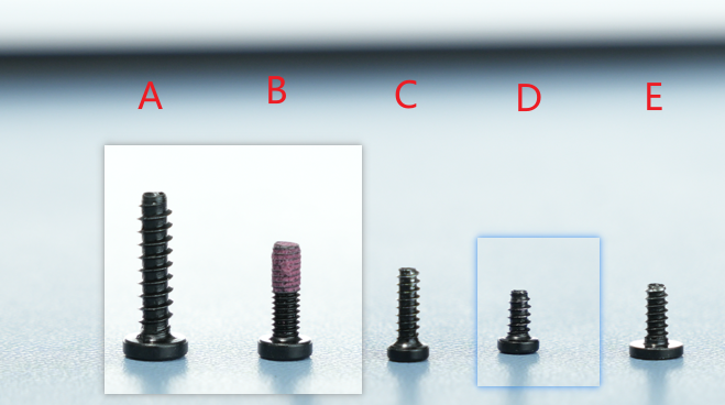
¶ Screw List
-
Screw A: 2 screws on the top of the extruder unit: BT3x12
-
Screw B: 2 screws on the bottom of the extruder unit: M2.5x5
-
Screw C: 3 screws on the back of the part cooling fan (co-locked with the rear cover) and the toolhead rear cover screws: BT2x6.5; 2 eddy current coil screws of the same size.
-
Screw D: 2 screws for the hotend fan: BT2x4
-
Screw E: 2 screws on the left and right sides of the part cooling fan: BT2x5
-
Extruder motor screws: not included in the figure below, 2 in total, M2.5x8 screws (same shape as screw B, with a thread length of 3cm)
¶ Safety Warning
It's crucial to power off the printer before conducting any maintenance work, including work on the printer's electronics and tool head wires. Performing tasks with the printer on can result in a short circuit, leading to electronic damage and safety hazards.
During maintenance or troubleshooting, you may need to disassemble parts, including the hotend. This exposes wires and electrical components that could short circuit if they contact each other, other metal, or electronic components while the printer is still on. This can result in damage to the printer's electronics and additional issues.
Therefore, it's crucial to turn off the printer and disconnect it from the power source before conducting any maintenance. This prevents short circuits or damage to the printer's electronics, ensuring safe and effective maintenance. For any concerns or questions about following this guide, open a new ticket in our Support Page and we will do our best to respond promptly and provide the assistance you need.
¶ Removing the 3513 Extruder Motor
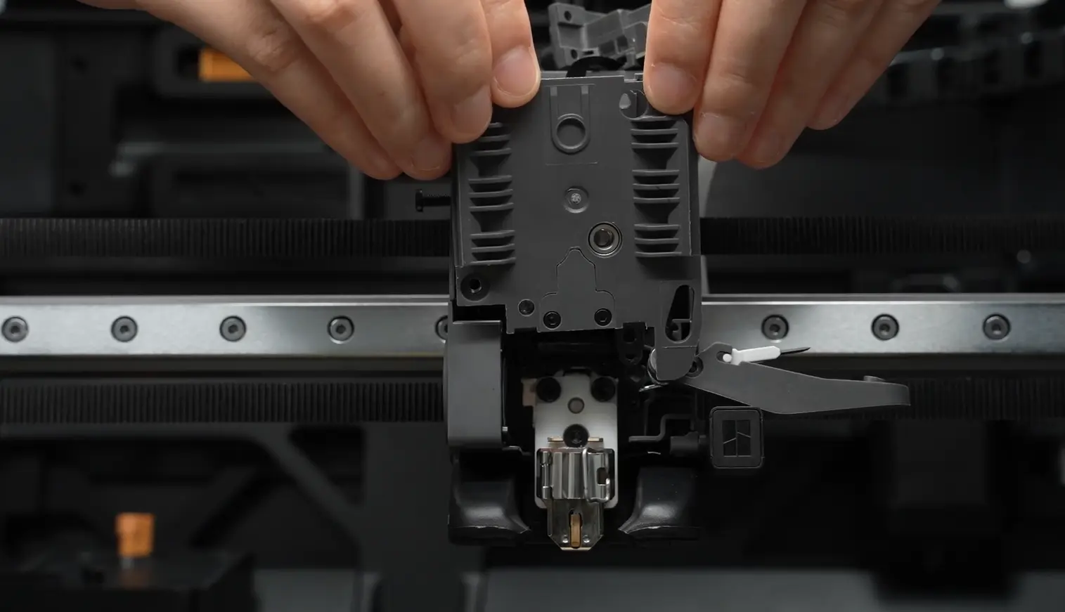
¶ Step 1: Remove the Extruder Unit
You can refer to this Wiki to remove the extruder unit from the toolhead to facilitate subsequent removal of the extruder motor: Replace H2S Extruder Unit
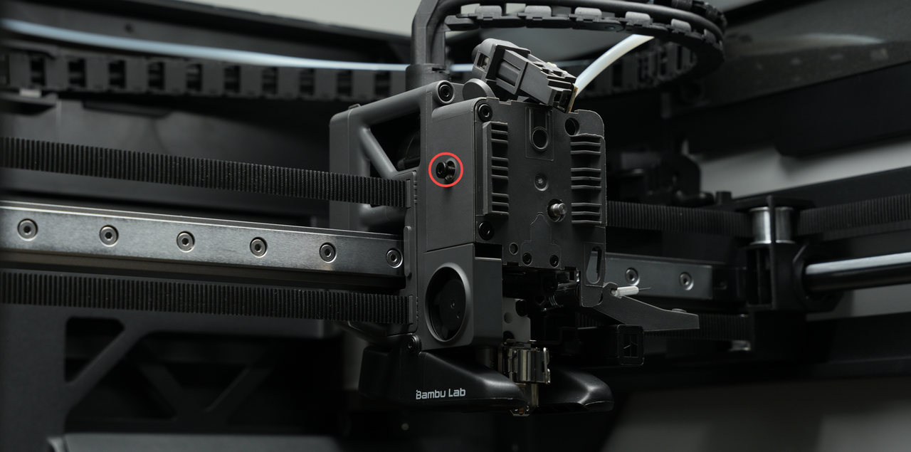
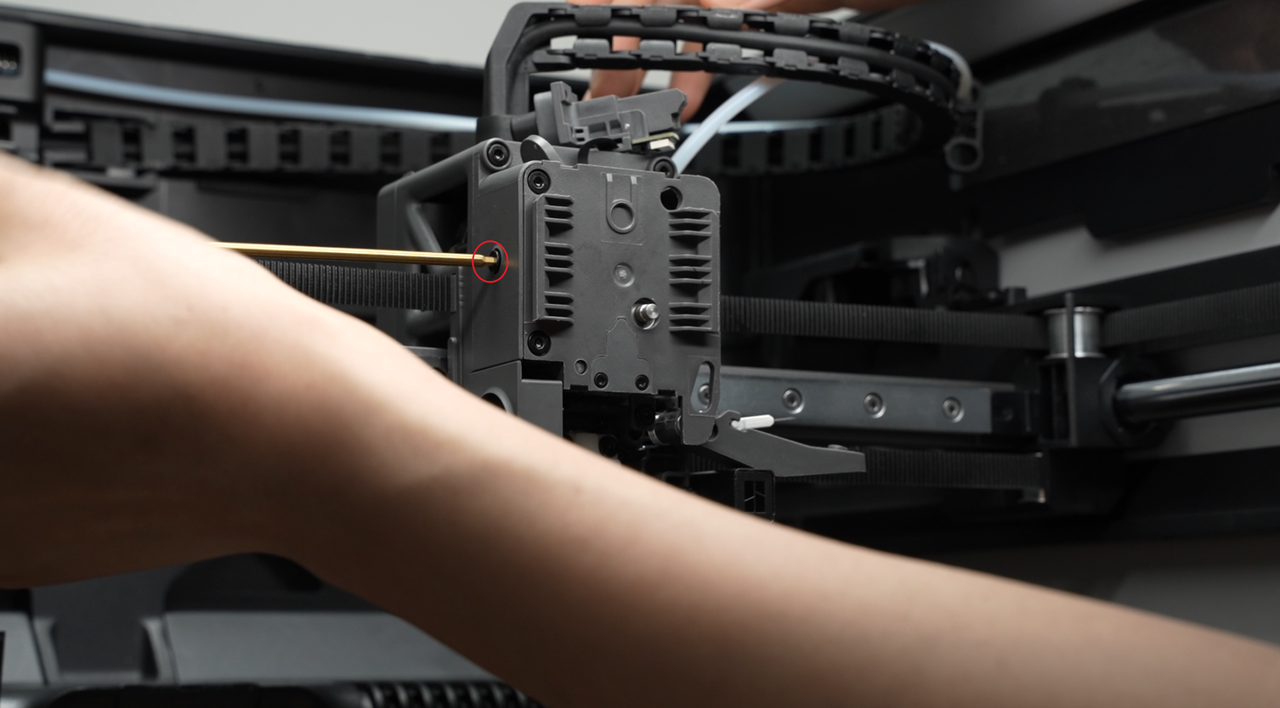
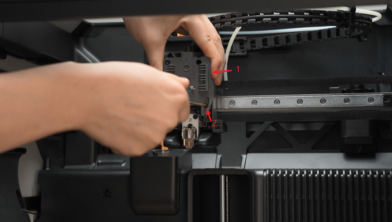
¶ Step 2: Loosen the Filament Cutter Lever
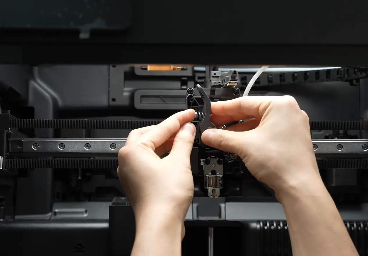
Place the extruder unit on the desktop and use an H2.0 hex screwdriver to remove one fixing screw of the filament cutter lever.
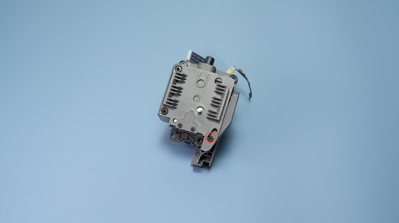
Note: After loosening the filament cutter lever, handle it with care to avoid being cut by the blade.
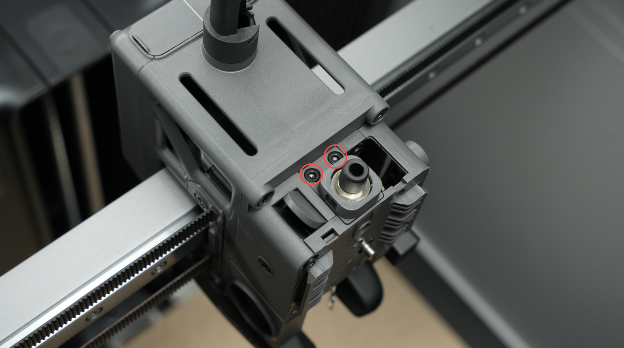
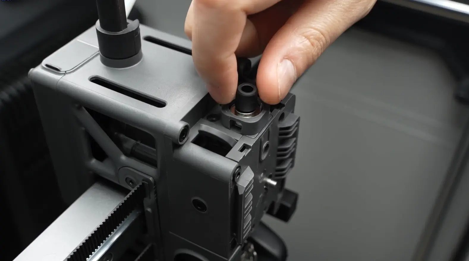
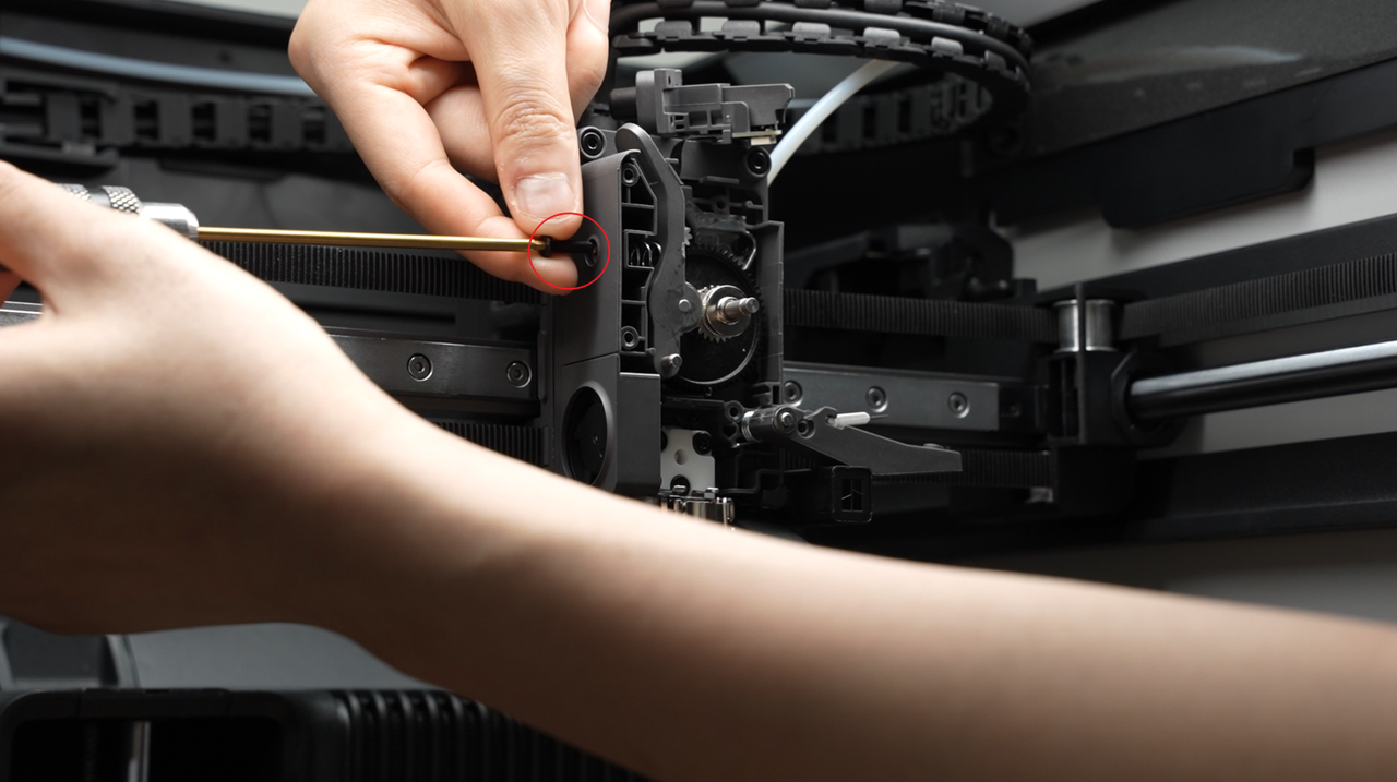
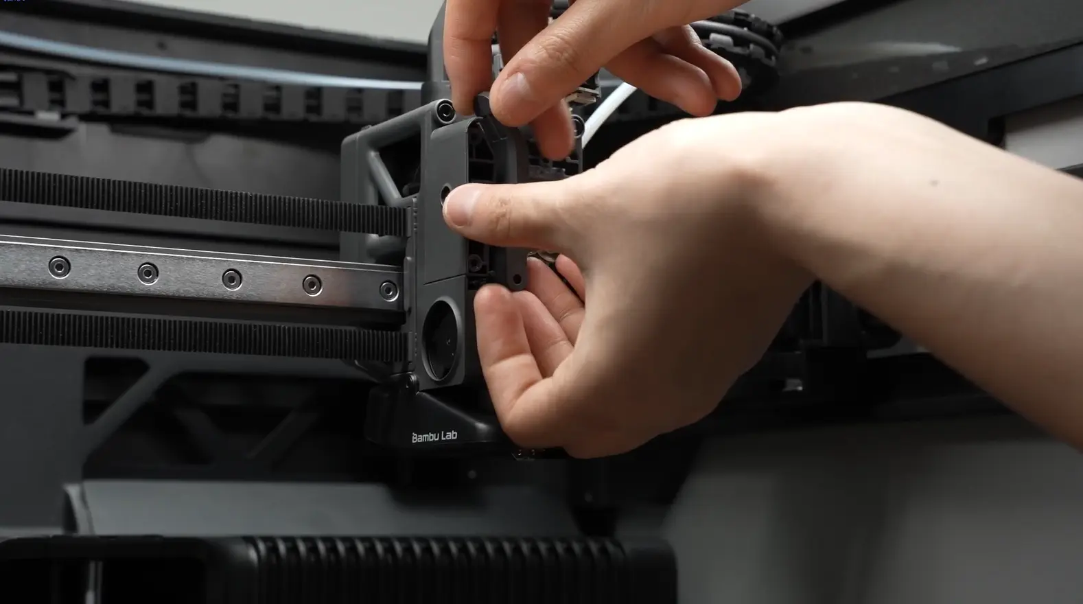
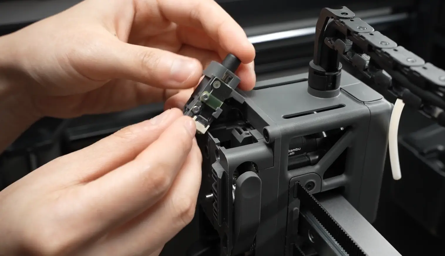
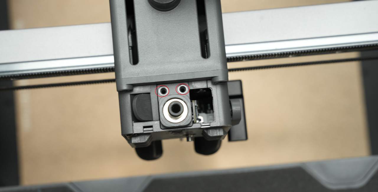
¶ Step 3: Remove the Feeder Filament Sensor
Use an H2.0 hex screwdriver to remove the 2 screws of the feeder filament sensor.
 |
 |
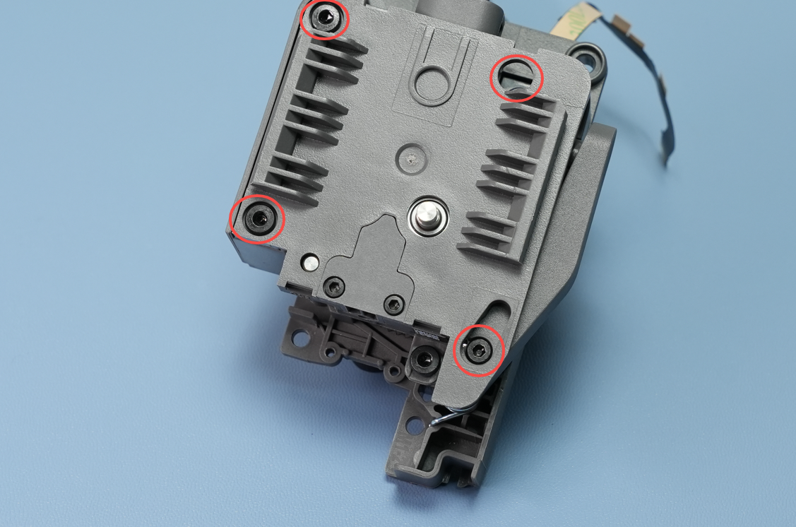
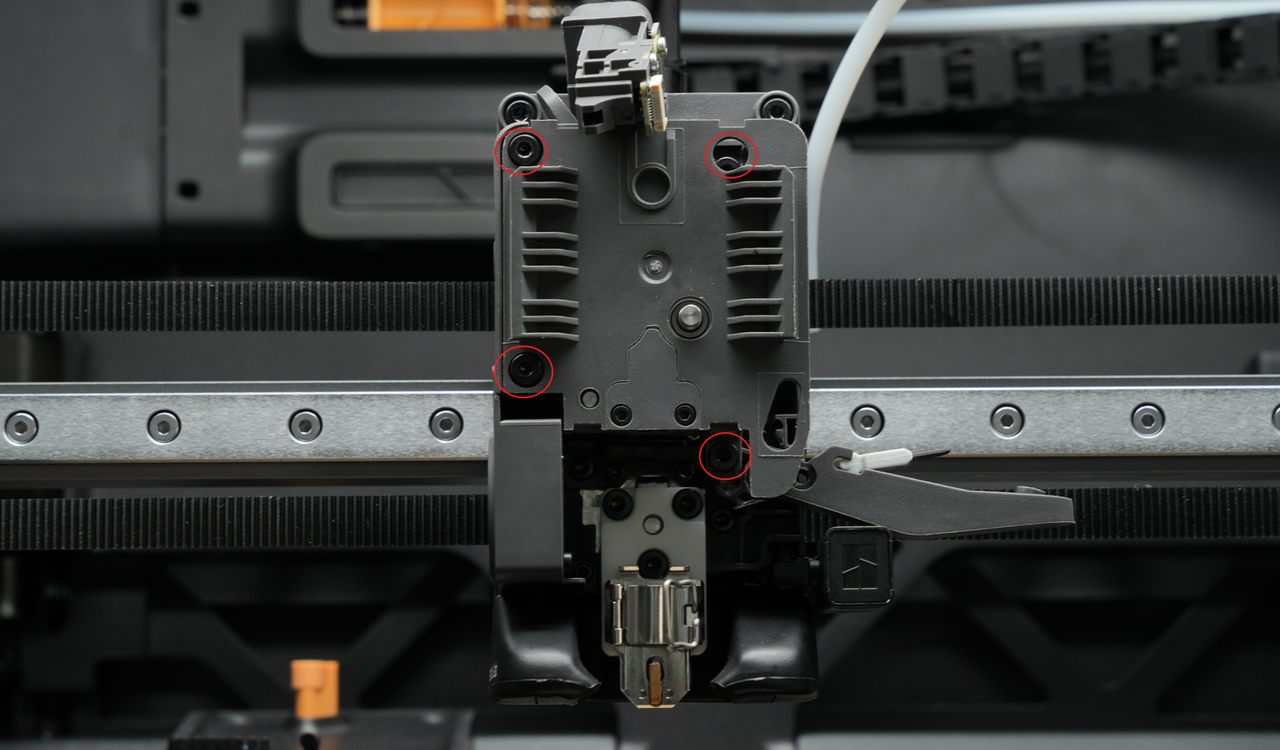
¶ Step 4: Remove the Extruder Front Cover and Extruder Gear
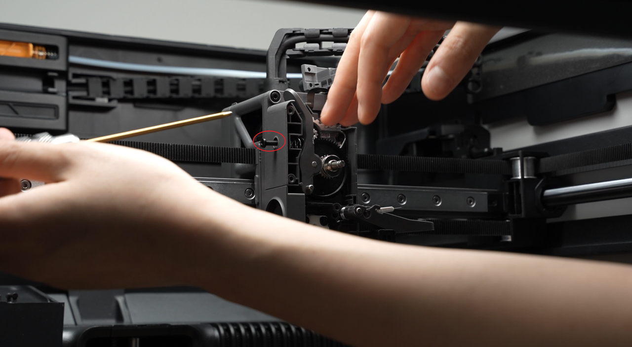
Use an H2.0 hex wrench to loosen the tension driven rod locking screw on the side by one turn;
Use an H2.0 hex wrench to remove the 4 screws on the front cover and take off the extruder front cover.
 |
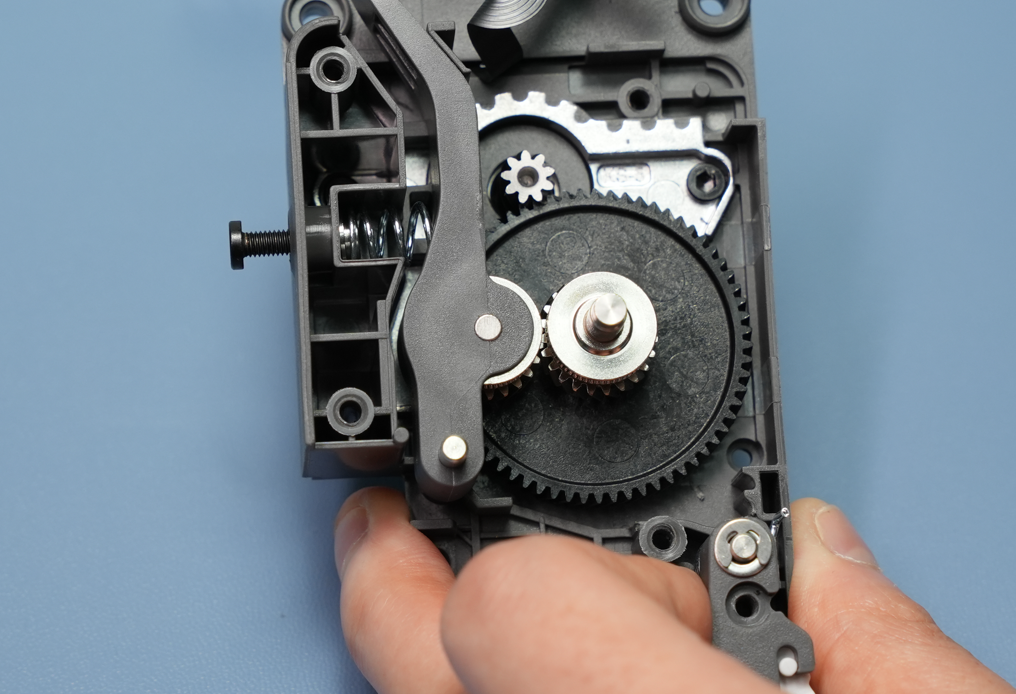 |
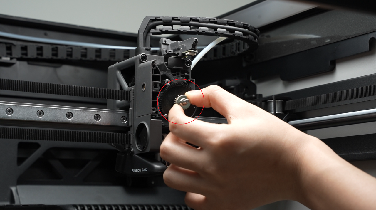
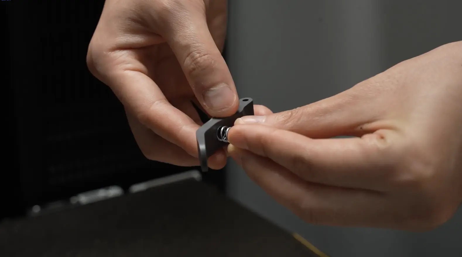
Use an H2.0 hex wrench to remove the side screw. When taking out the bracket, the internal spring and end cap are easy to fall off, so take them out carefully to prevent loss.
Shake left and right to directly take out the large gear of the extruder.
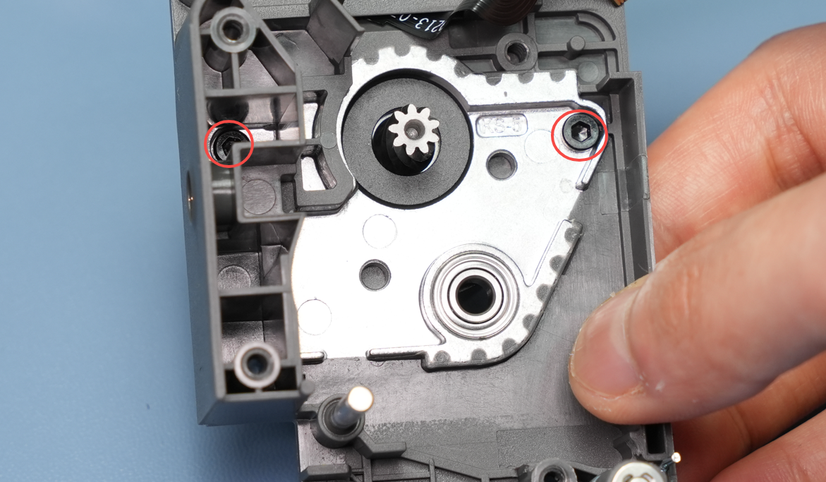
¶ Step 5: Remove the Extruder Motor Screws
Remove the 2 extruder motor screws and take off the extruder motor.
¶ Installing the 3513 Extruder Motor
¶ Step 1: Install the 3513 Extruder Motor
Align the new extruder motor with the holes on the extruder rear cover, then use an H2.0 hex screwdriver to tighten the two fixing screws.

¶ Step 2: Install the Extruder Front Cover and Extruder Gear
Install the extruder gear.
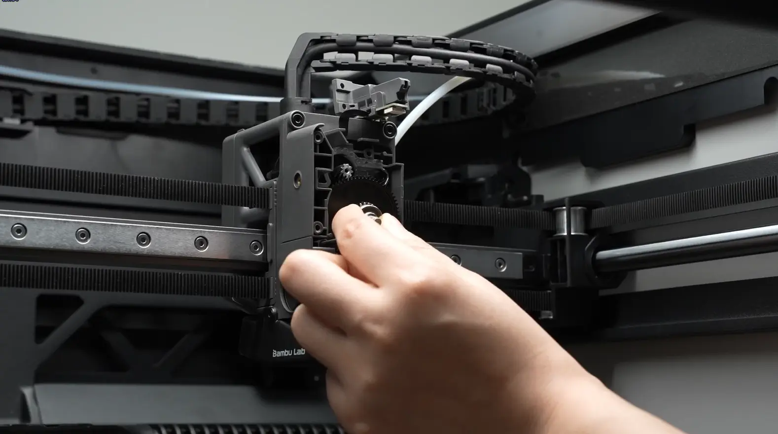
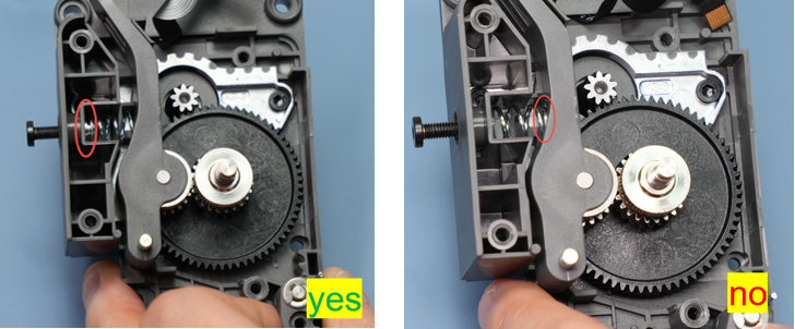
Install the driven wheel bracket onto the corresponding rotating shaft. Assemble the spring and end cap in the correct direction and position (please refer to the correct and incorrect demonstrations below), place them in the corresponding position of the driven wheel bracket, screw in the side screw to hold it, but do not fully tighten it yet.
Important Reminder!
Be sure to install the spring and end cap correctly, otherwise the extruder will not be able to grip the filament, resulting in printing failure.
Pre-lock the side screw, screwing it in 2-3 turns is sufficient, do not fully tighten it, otherwise it will bring difficulty in installing the front cover.
Reinstall the extruder front cover and screw in the 4 screws of the extruder front cover.
 |
 |
Tighten the extruder side screw;
¶ Step 3: Install the Feeder Filament Sensor
Install the filament hub unit, ensuring that the black FPC cable is not folded and is smoothly placed in the vacant position. Then screw in 2 screws to fix the feeder filament sensor. Before screwing in the screws, check from above that the flat cable does not press against the screw holes to avoid damage to the flat cable caused by the screws.
 |
 |
¶ Step 4: Install the Filament Cutter Lever
Before re-fixing the screw, hold the filament cutter lever firmly and keep it in position. When tightening the screw, be careful not to apply excessive force to prevent thread stripping.
¶ Step 5: Install the Extruder Unit
You can refer to this Wiki to reinstall the extruder unit onto the toolhead:
¶ How to Verify Success
-
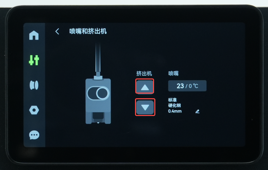
Connect the power supply and start the printer;
-
On the control page, click the extruder extrusion button to confirm that the motor can drive the extruder normally;
¶ End Notes
We hope the detailed guide provided has been helpful and informative.
If this guide does not solve your problem, please submit a technical ticket, we will answer your questions and provide assistance.
If you have any suggestions or feedback on this Wiki, please leave a message in the comment area. Thank you for your support and attention!