The toolhead camera is installed on the right side of the toolhead and can be used for motion accuracy calibration, and identification of build plate and laser pad identification codes. The toolhead camera and its accessories are as follows:
-
Toolhead Camera * 1
-
BT2x8 Screw * 2
¶ When to Replace?
-
Toolhead camera reports an error
-
Recommended by Bambu Lab technical support
¶ Required Tools and Materials
- New toolhead camera
-
H1.5 Hex Key Wrench
-
25 minutes
¶ Screw List
-
Screw A: 3 screws on the back of the part cooling fan (co-locked with the rear cover) and the toolhead rear cover screws: BT2x6.5
-
Screw B: 2 screws for the toolhead camera: BT2*8
-
Screw C: 2 screws on the left and right sides of the part cooling fan: BT2x5

¶ Safety Warning
It's crucial to power off the printer before conducting any maintenance work, including work on the printer's electronics and tool head wires. Performing tasks with the printer on can result in a short circuit, leading to electronic damage and safety hazards.
During maintenance or troubleshooting, you may need to disassemble parts, including the hotend. This exposes wires and electrical components that could short circuit if they contact each other, other metal, or electronic components while the printer is still on. This can result in damage to the printer's electronics and additional issues.
Therefore, it's crucial to turn off the printer and disconnect it from the power source before conducting any maintenance. This prevents short circuits or damage to the printer's electronics, ensuring safe and effective maintenance. For any concerns or questions about following this guide, open a new ticket in our Support Page and we will do our best to respond promptly and provide the assistance you need.
¶ Removing the Toolhead Camera
¶ Step 1: Loosen the Part Cooling Fan
- Unscrew the 3 screws of the part cooling fan, among which 1 screw on the back is co-locked with the toolhead rear cover.
 |
 |
|---|

- After loosening the screws, the fan will hang down naturally. Do not pull the fan to avoid damaging the connector!

¶ Step 2: Loosen the Toolhead Rear Cover
- Remove the 2 screws above the toolhead rear cover and open the module interface cover;
 |
 |
|---|
- After opening the interface cover, you can insert your fingers into the inner wall, apply slight force, and push the toolhead rear cover backward.
 |
 |
|---|
¶ Step 3: Disconnect the Connector on the TH Board
- Disconnect the hotend heating assembly plug;

- Tear off the acetate tape on the part cooling fan plug;
Please keep the tape as it needs to be reattached during installation.
 |
 |
|---|
- Pinch the root of the connector, apply force in the direction perpendicular to the PBC board, and disconnect the part cooling fan plug.

- Disconnect the toolhead camera plug

¶ Step 4: Remove the Hotend
- Refer to this tutorial to remove the hotend (click here to jump)
¶ Step 5: Remove the Toolhead Camera
- Take out the part cooling fan cable and hotend heating cable from the cable management slot; (Note: In this step, you only need to pull out the part cooling fan and hotend heating assembly cables to facilitate pulling out the toolhead camera cable, and there is no need to unscrew the screws to remove these 2 components)
 |
 |
|---|
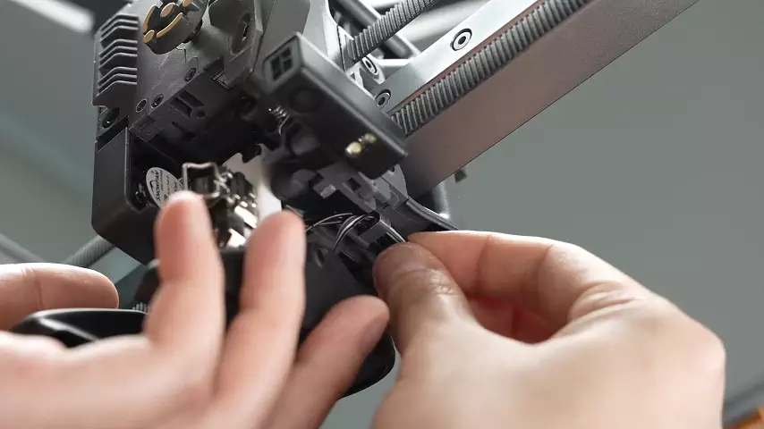
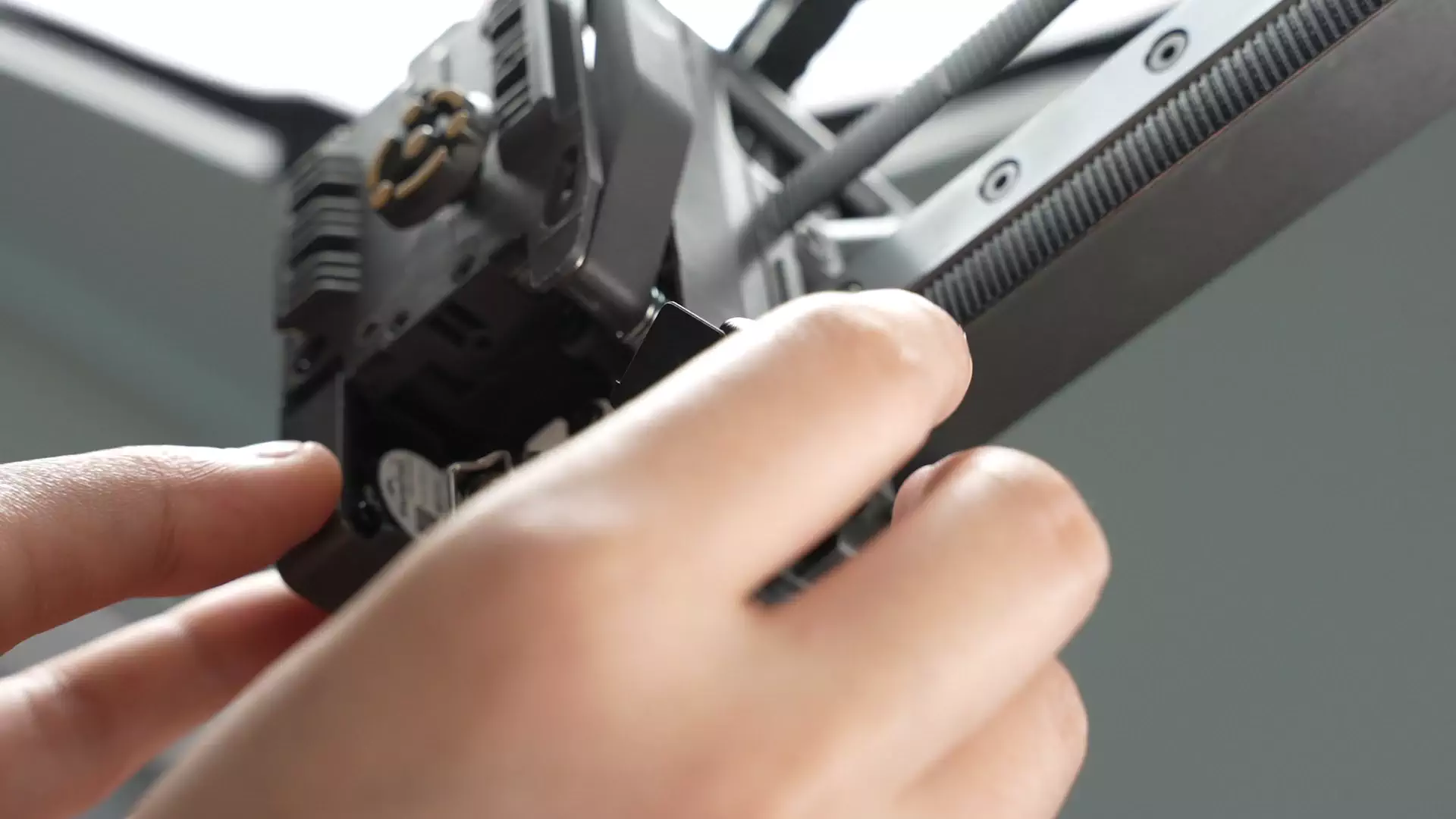
- Pry open the toolhead camera cover and unscrew the 2 exposed screws, one of which requires inserting a screwdriver under the flat cable. It is recommended to first loosen screw 1 by several turns, then fully unscrew screw 2, and then fully unscrew screw 1.
 |
 |
|---|
- Remove the flat cable from the toolhead frame. For some batches, the flat cable at the buckle has adhesive on the back, so it needs to be loosened by shaking left and right.
¶ Installing the Toolhead Camera
¶ Step 1: Install the New Toolhead Camera
- Tear off the adhesive protective layer on the back of the toolhead camera. As shown in the animation, bend the flat cable closest to the internal circuit board end of the toolhead camera by 90 degrees and stick it to the housing.


- Pre-align the screw holes, pass the flat cable through the cable trough, and stick the remaining adhesive of the flat cable to the corresponding position of the middle frame.
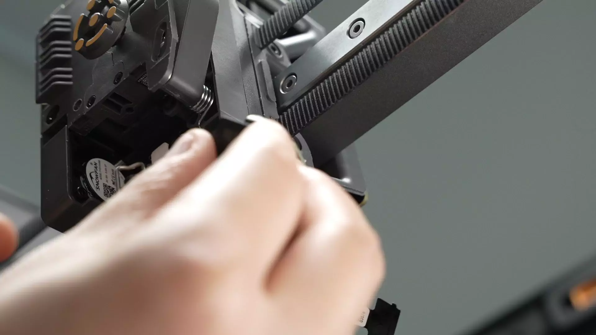
- Align the screw holes, install the toolhead camera back, and tighten the 2 fixing screws; when screwing in the screws, first pre-lock screw 1 for several turns, then fully tighten screw 2, and then continue to tighten screw 1.
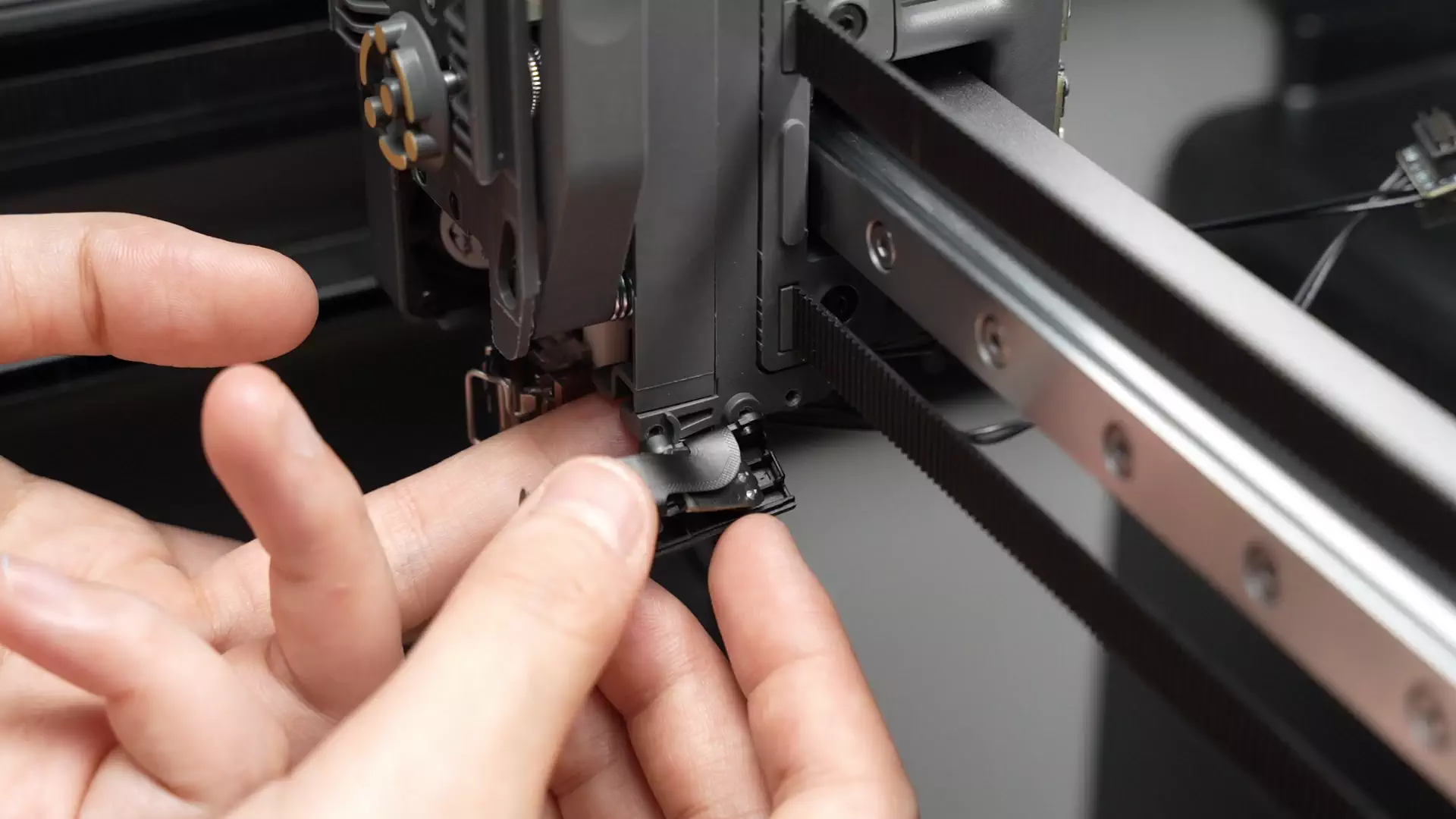

- Snap back the toolhead camera cover

- Clip the new hotend heating assembly cable into the cable management slot. After clipping in the cable, press the arrow as shown in the video.

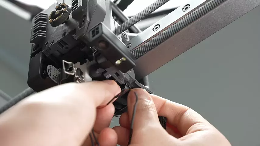
- Clip the cable of the part cooling fan into the cable clip;

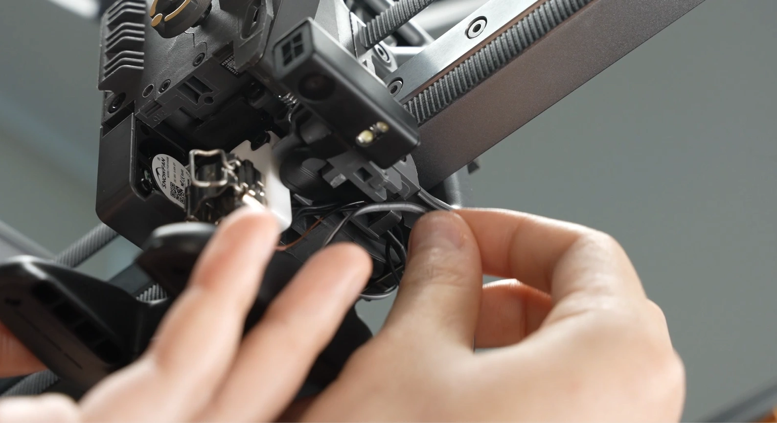
¶ Step 2: Install the Hotend
- Refer to this tutorial to install the hotend (click here to jump)
¶ Step 3: Connect the Connector on the TH Board
- Connect the toolhead camera plug

- Connect the fan cable, with the jack face of the plug facing the socket on the TH board (the metal solder points of the plug face the back of the chassis), align and press down the plug;
 |
 |
|---|
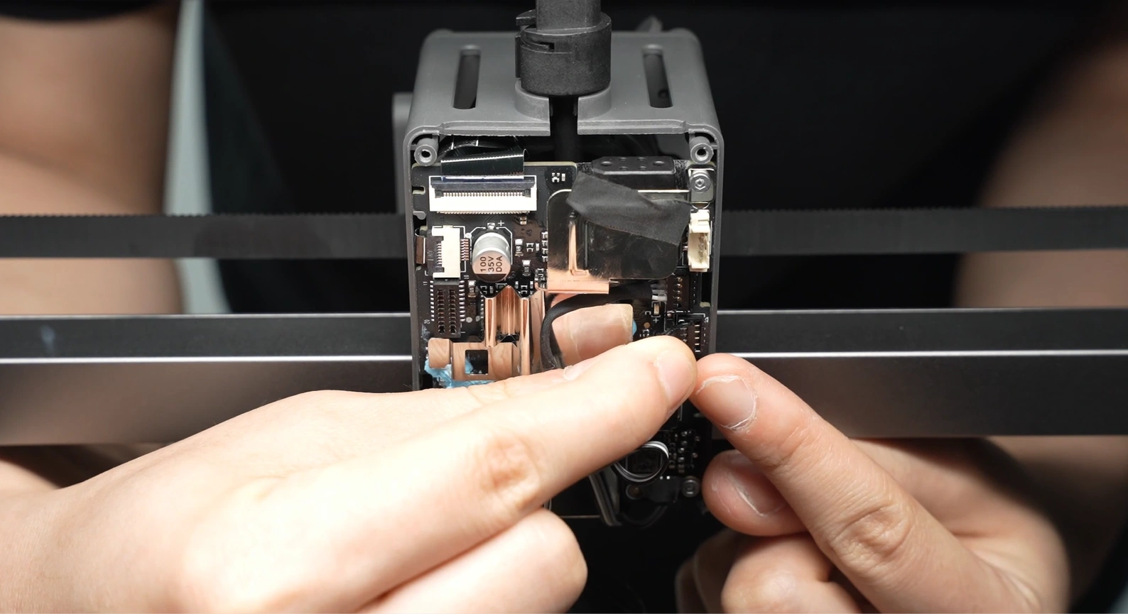
- Stick back the acetate tape;

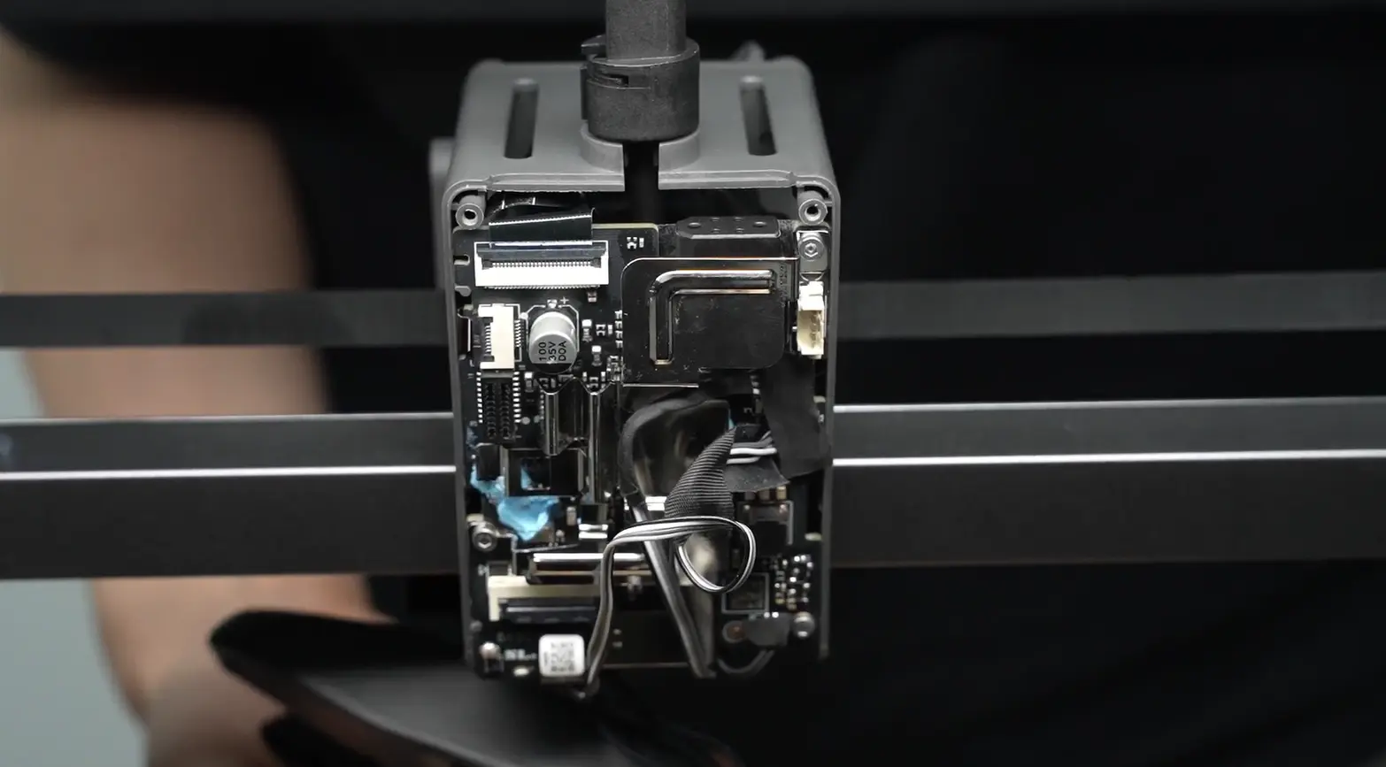
- Pre-align the screw holes of the fan, arrange the fan cable on the TH board, and pull upward to fold the excess cable to avoid being crushed by the fan housing or toolhead rear cover, which may cause fan abnormalities.
 |
 |
|---|
- After organizing the cables, insert the hotend heating assembly plug, and use the hotend heating assembly plug and cable to press the part cooling fan cable.
 |
 |
|---|
When inserting the hotend heating assembly, ensure that the holes are aligned correctly and do not misalign.

¶ Step 4: Install the Toolhead Rear Cover
- Install the toolhead rear cover;

- After installation, check whether the part cooling fan cable is located in the dedicated notch to avoid being squeezed by the rear cover frame;
 |
 |
|---|
- Lock in 2 rear cover fixing screws.

¶ Step 5: Install the Part Cooling Fan
- Align the screw holes and install the part cooling fan; when clipping in the fan, be careful not to press the fan cable.
If the cable is too long, you need to return to step 1 of the installation guide and first fold the excess cable.

- Lock in 3 screws to fix the part cooling fan.
 |
 |
|---|

¶ Function Confirmation
To ensure everything is working properly, set the hotend temperature to 100°C. If the setting is successful, the corresponding temperature will be displayed on the screen.
¶ Equipment Calibration
It is recommended to perform a full calibration of the printer after this operation.
It is strongly recommended to clean the PEI textured plate before use as the build plate may have been contaminated during this process.
¶ Potential Problems and Solutions
If you encounter problems during the installation of the new hotend heating assembly, check the following potential problems and solutions:
¶ Hotend Temperature is 0°C
- Check the hotend heating assembly connector to ensure it is properly inserted.
- Please refer to Step 5 Connect Cables.
- The connector pins must be carefully aligned with the TH Board.
If the problem persists, the thermistor wire may be damaged (white wire).
¶ Hotend Cannot Heat
- Check the hotend heating assembly connector to ensure it is properly inserted.
- Please refer to Step 5 Connect Cables.
- The connector pins must be carefully aligned with the TH Board.
If the problem persists, the heater wire may be damaged (translucent wire).
¶ First Layer Issues
-
Ensure that the screws of the hotend heater assembly are tightened and that the heatbed leveling function is enabled before starting printing.
-
Please refer to A1 Series First Layer Printing Quality Issues and Corresponding Solutions for more related issues and solutions.
¶ End Notes
We hope the detailed guide provided has been helpful and informative.
If this guide does not solve your problem, please submit a technical ticket, we will answer your questions and provide assistance.
If you have any suggestions or feedback on this Wiki, please leave a message in the comment area. Thank you for your support and attention!