¶ USB-C Cable
The USB-C cable is used to connect the TH Board and the AP Board.
The spare parts of the USB-C cable include the following:
USB-C Cable * 1
¶ When to Replace
-
The USB-C cable is damaged;
-
Replacement is confirmed necessary by Bambu Lab's official technical support.
¶ Required Tools and Materials
-
New USB-C cable
-
H2.0 Hex Wrench
-
H1.5 Hex Wrench
¶ Screw List:
-
Screw A: 3 screws on the back of the part cooling fan (co-locked with the rear cover) and the toolhead rear cover screws: BT2x6.5
-
Screw B: 2 screws on the left and right sides of the part cooling fan: BT2x5
-
Screw C: 2 screws for the TH Board: BT2x5
-
Screw D: 1 screw for the AP Board cover: BT2.6x8, not included in the figure below
-
Screw E: 1 screw for the USB-C cable clip
-
Screw F: Buffer fixing screws, BT3*8, 4 in total

¶ Safety Warning
It's crucial to power off the printer before conducting any maintenance work, including work on the printer's electronics and tool head wires. Performing tasks with the printer on can result in a short circuit, leading to electronic damage and safety hazards.
During maintenance or troubleshooting, you may need to disassemble parts, including the hotend. This exposes wires and electrical components that could short circuit if they contact each other, other metal, or electronic components while the printer is still on. This can result in damage to the printer's electronics and additional issues.
Therefore, it's crucial to turn off the printer and disconnect it from the power source before conducting any maintenance. This prevents short circuits or damage to the printer's electronics, ensuring safe and effective maintenance. For any concerns or questions about following this guide, open a new ticket in our Support Page and we will do our best to respond promptly and provide the assistance you need.
¶ Removing the USB-C Cable
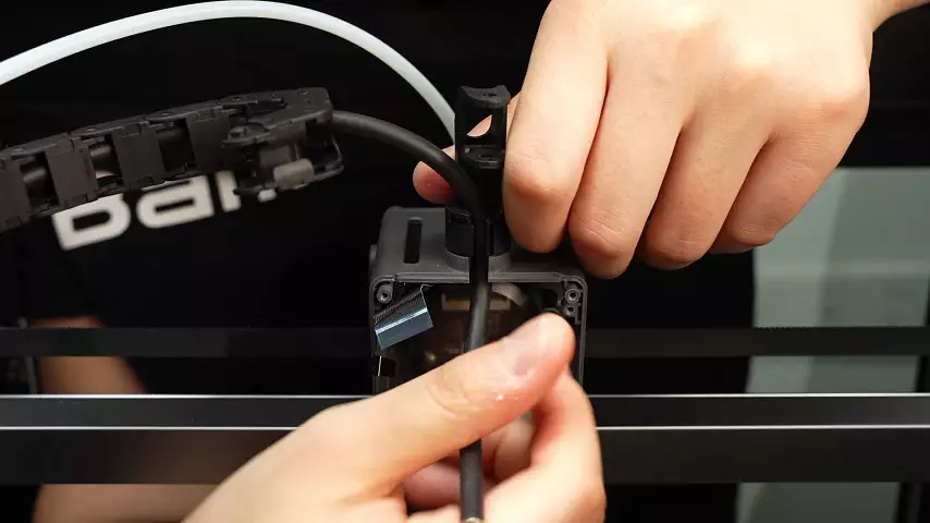
¶ Step 1: Disconnect the USB-C data cable from the TH board and pull the cable out of the cable chain bracket.
Since the USB-C cable is connected to the back of the TH board, you need to first loosen the connector on the front of the TH board, flip the TH board over, and then unplug the USB-C cable from the TH board. You can refer to this Wiki to remove the TH board and then disconnect the USB-C connection. You only need to follow the steps for disconnecting the TH board from the USB-C cable.
Pull the cable out of the drag chain bracket.
¶ Step 2: Remove the AP Board Cover and Filament Cable Management Cover
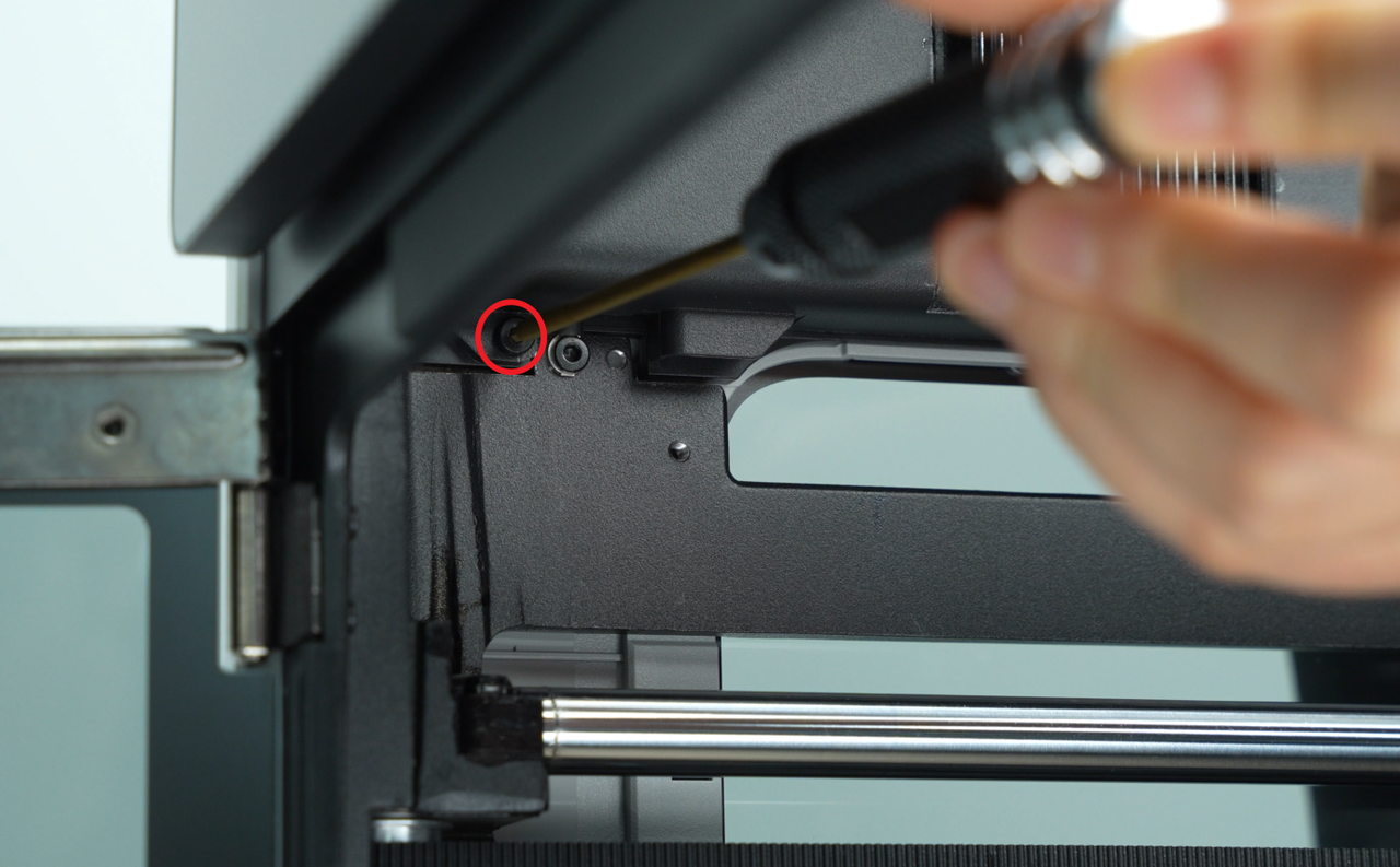
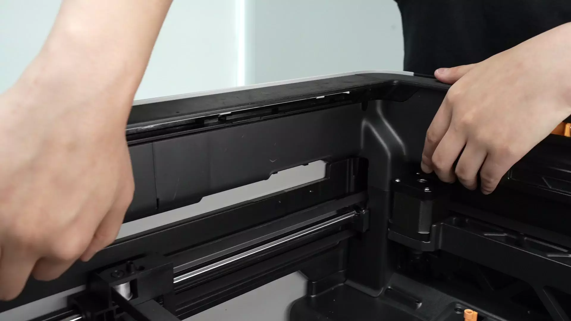
Use an H2.0 hex wrench to unscrew 1 fixing screw (BT2.6x8), then remove the AP Board cover from the side near the front door.
¶ Step 3: Remove the Buffer
Press the pneumatic connector on the tube holder to unlock it, and remove the PTFE tube connected to the back of the printer;

Push out the pneumatic connector, press the pneumatic connector on the buffer to unlock it, and remove the PTFE tube inside the printer
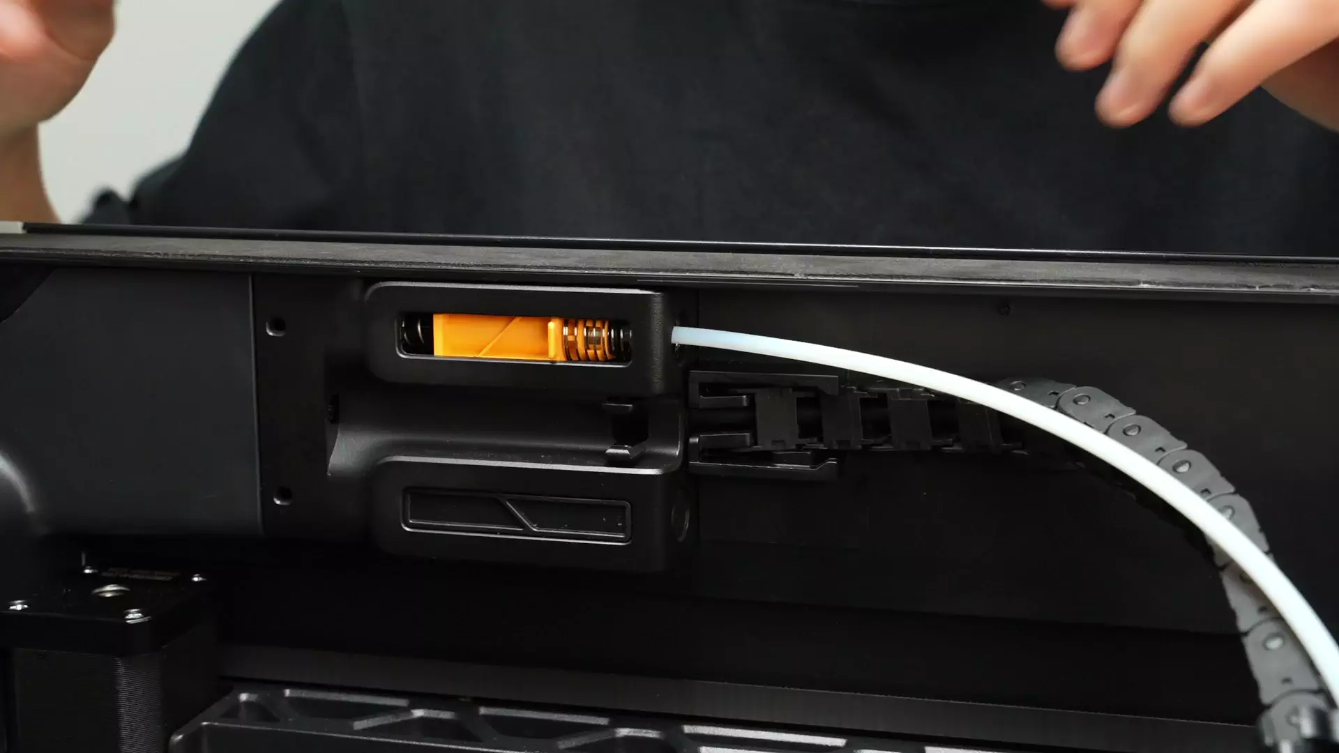
Use an H2.0 hex wrench to remove the four fixing screws and loosen the buffer.


¶ Step 4: Loosen the Cable Chain
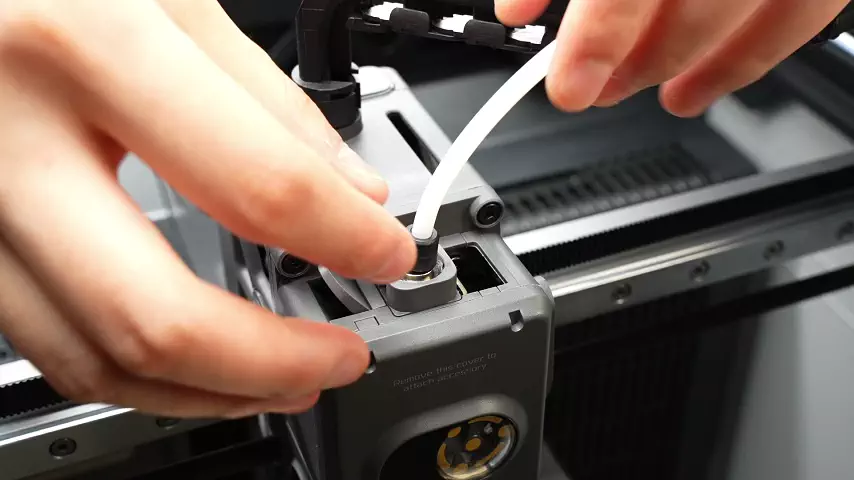
Press the pneumatic connector above the toolhead to disconnect the PTFE tube above the toolhead, and pull it out from the cable chain


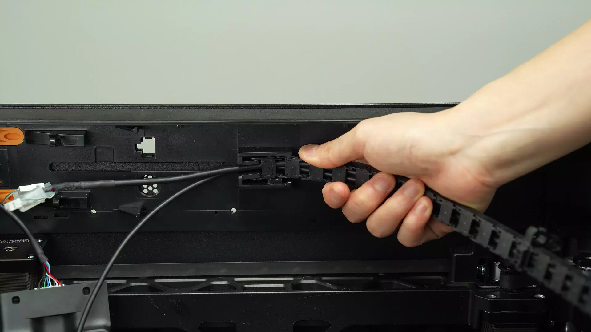
Disconnect the cable chain from the printer frame (taking the H2D model operation as an example, the H2S operation method is exactly the same)
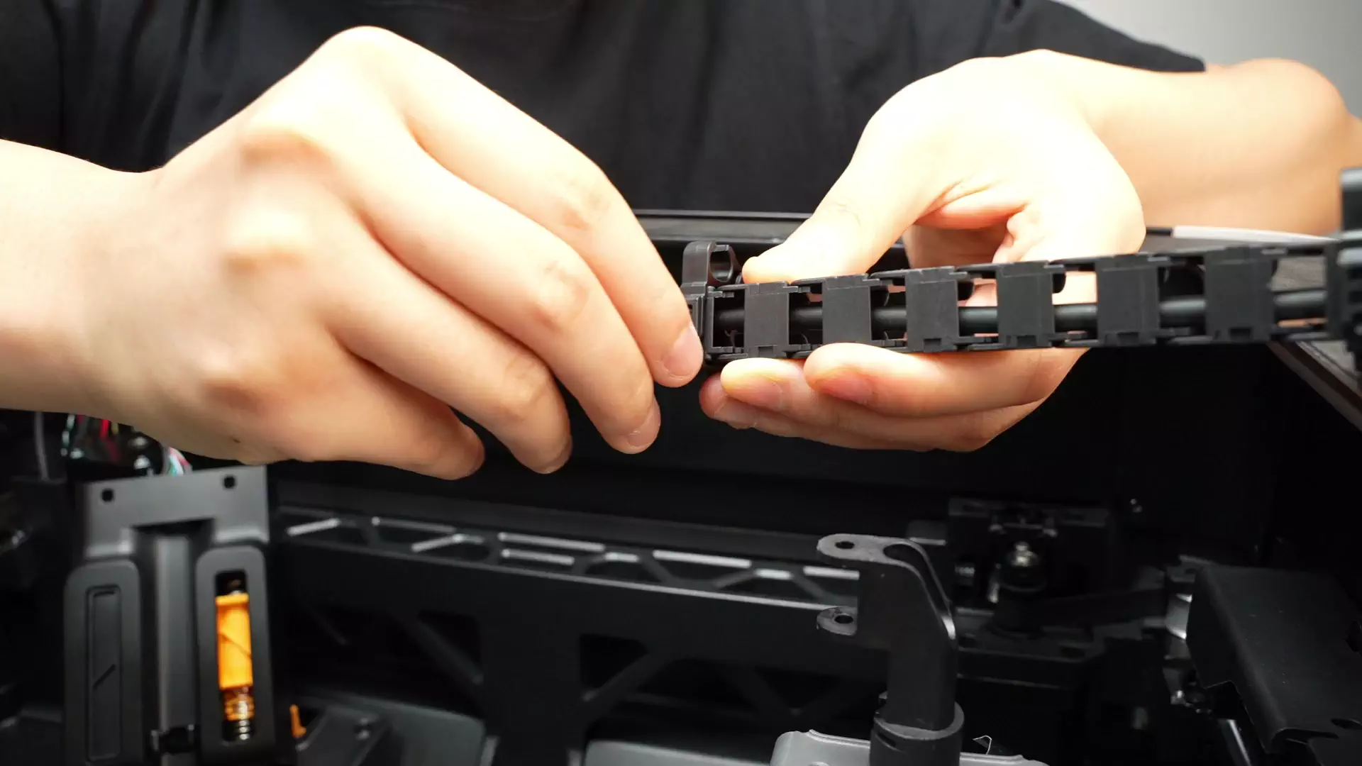
Disconnect the 2 PTFE tube buckles on the cable chain
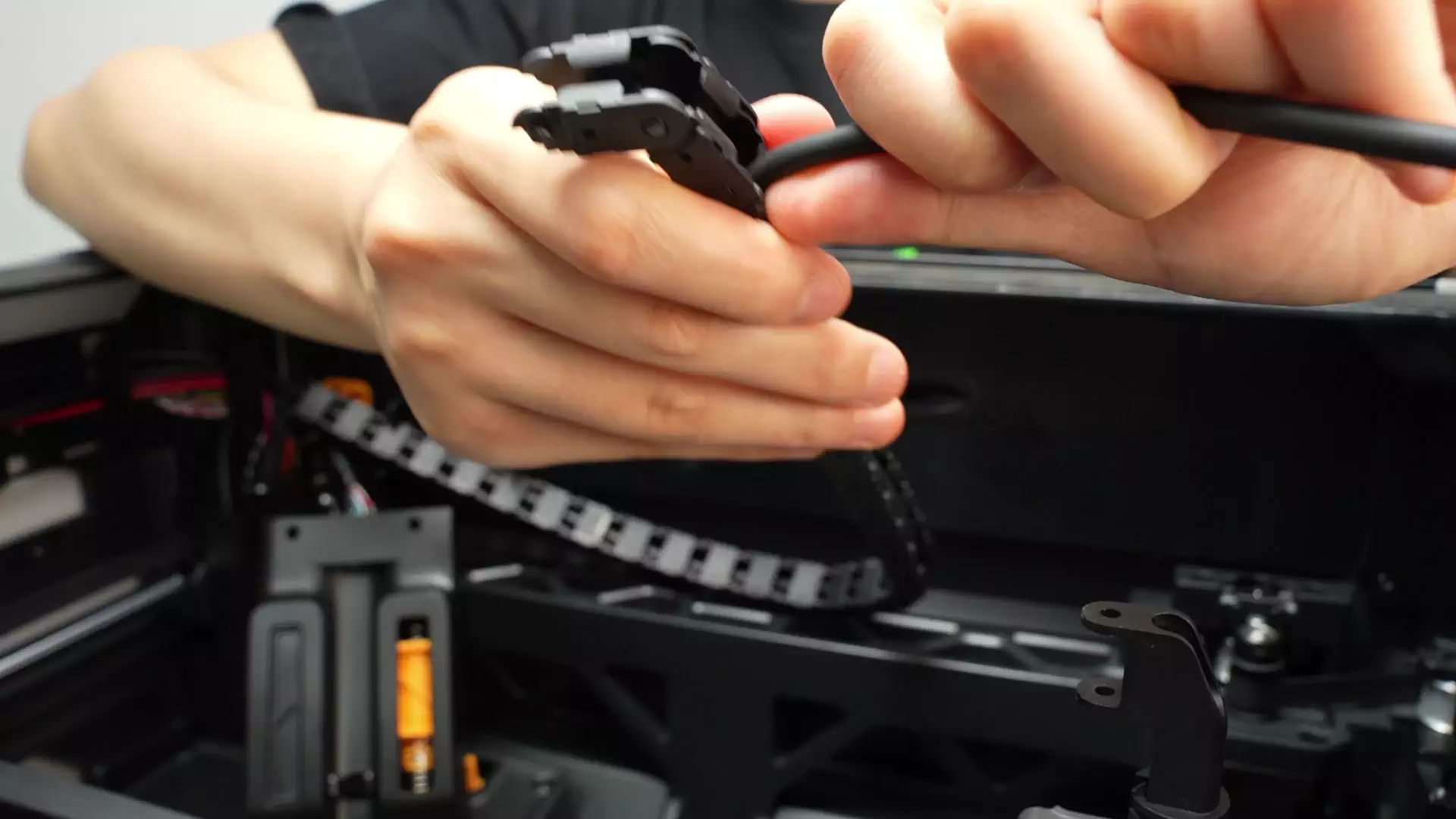
Pull the USB-C cable out of the cable chain
¶ Step 4: Disconnect the USB-C Cable from the AP Board
- Pull the USB-C cable out of the buckle

- Unscrew the screw in the USB-C cable management clip.

- Pull the cable out of the buckle and disconnect the USB-C cable;

¶ Installing the USB-C Cable
¶ Step 1: Connect the USB-C Cable to the AP Board
When connecting the new USB-C cable, note that there is anti-shake tape on the surface of the plug, so you need to use some force to insert it until you feel that it can no longer be pushed; this means it is inserted in place.
Note: The end with the letter "A" is connected to the AP Board, and the letter "A" faces outward!

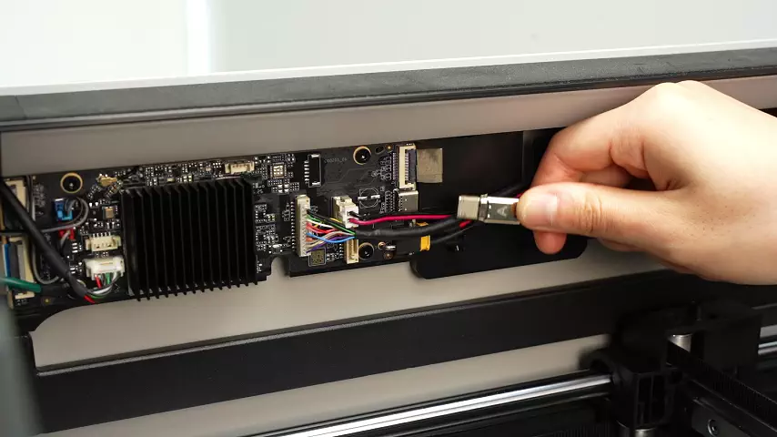
Then, insert the cables into the cable clips in sequence and secure it by locking the screw of the clip.


¶ Step 2: Install the Cable Chain
- Load the USB-C cable into the cable chain with the opening facing outward, pull the cable back and forth to leave an appropriate length;

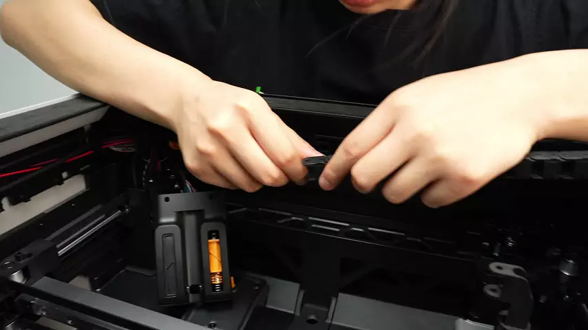
Connect the cable chain to the printer frame (taking the H2D model operation as an example, the H2S operation method is exactly the same)
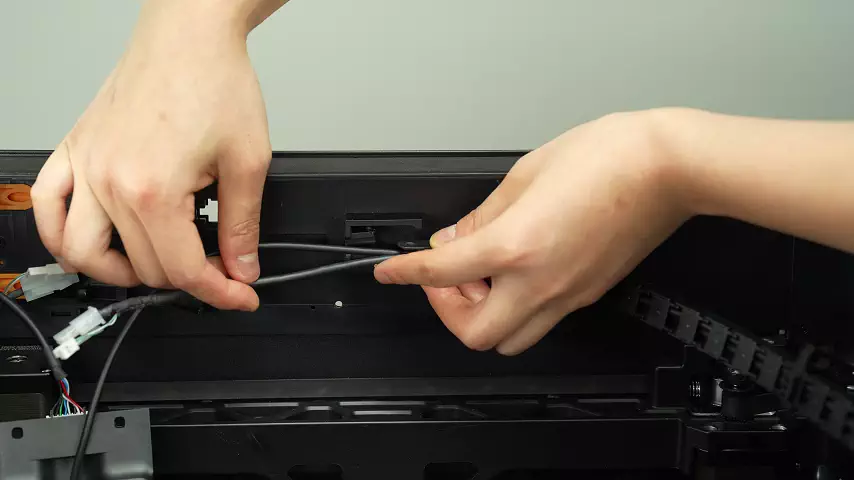
Reinstall the cable chain buckles, clipping them into the 11th and 18th sections respectively


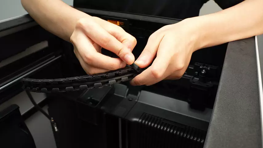
Thread the PTFE tube through and connect the pneumatic connector


¶ Step 4: Install the Buffer
Clip the USB-C cable into the groove in the frame, align with the holes, and reinstall the buffer.


After aligning the buffer with the screw holes, use an H2.0 hex wrench to tighten the four fixing screws (BT3×8), and finally reconnect the two PTFE tubes to the buffer.

¶ Step 5: Install the AP Board Cover
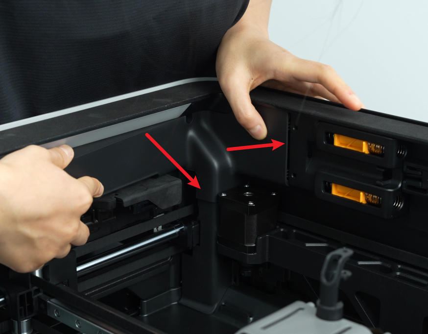
First, clip back the AP Board cover from the side near the back of the printer, press both places indicated by the arrows into place, with the right side flush with the buffer and the bottom flush with the cable protection cover, then use an H2.0 hex wrench to tighten one fixing screw (BT2.6x8).

Note: Before installing the AP Board cover, check whether the cable blocks the PTFE pipeline to avoid affecting the subsequent installation of the PTFE tube.

¶ Step 3: Connect the USB-C Cable to the TH Board
Insert the USB-C cable into the drag chain bracket.
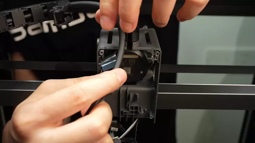
Refer to the TH Board installation tutorial, connect the USB-C cable plug at the TH Board end, and reinstall the TH Board

¶ How to Verify Success
Connect the power supply and turn on the printer; if no error is reported when initiating printing, it is successful.
¶ End Notes
We hope the detailed guide provided has been helpful and informative.
If this guide does not solve your problem, please submit a technical ticket, we will answer your questions and provide assistance.
If you have any suggestions or feedback on this Wiki, please leave a message in the comment area. Thank you for your support and attention!