¶ Overview
When designing functional parts, especially mechanical components and interlocking pieces, even the slightest deviation in print size can result in misfits or failed assemblies. Most filaments exhibit thermal shrinkage, meaning the final print may be slightly smaller than intended, especially in the X and Y dimensions. For example, you designed a part to be exactly 100 mm wide, but after printing, it measures only 94 mm. This means your print shrank by 6%. The shrinkage is not due to printer malfunction but rather the behavior of the material. The amount of shrinkage varies depending on the type of filament used.
To address this, Bambu Studio features a shrinkage compensation setting to help mitigate this common issue. It scales the 3D model to counteract the contraction that occurs in some materials as they cool after extrusion.
¶ How Shrinkage Compensation Works in Bambu Studio
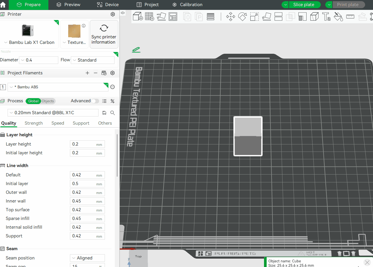
Bambu Studio includes a shrinkage compensation setting within the filament profile. This means you can define shrinkage values per filament roll. Once you open Bambu Studio and choose the filament you will be using in your project, click the three dots at the end of the filament, then click Edit.
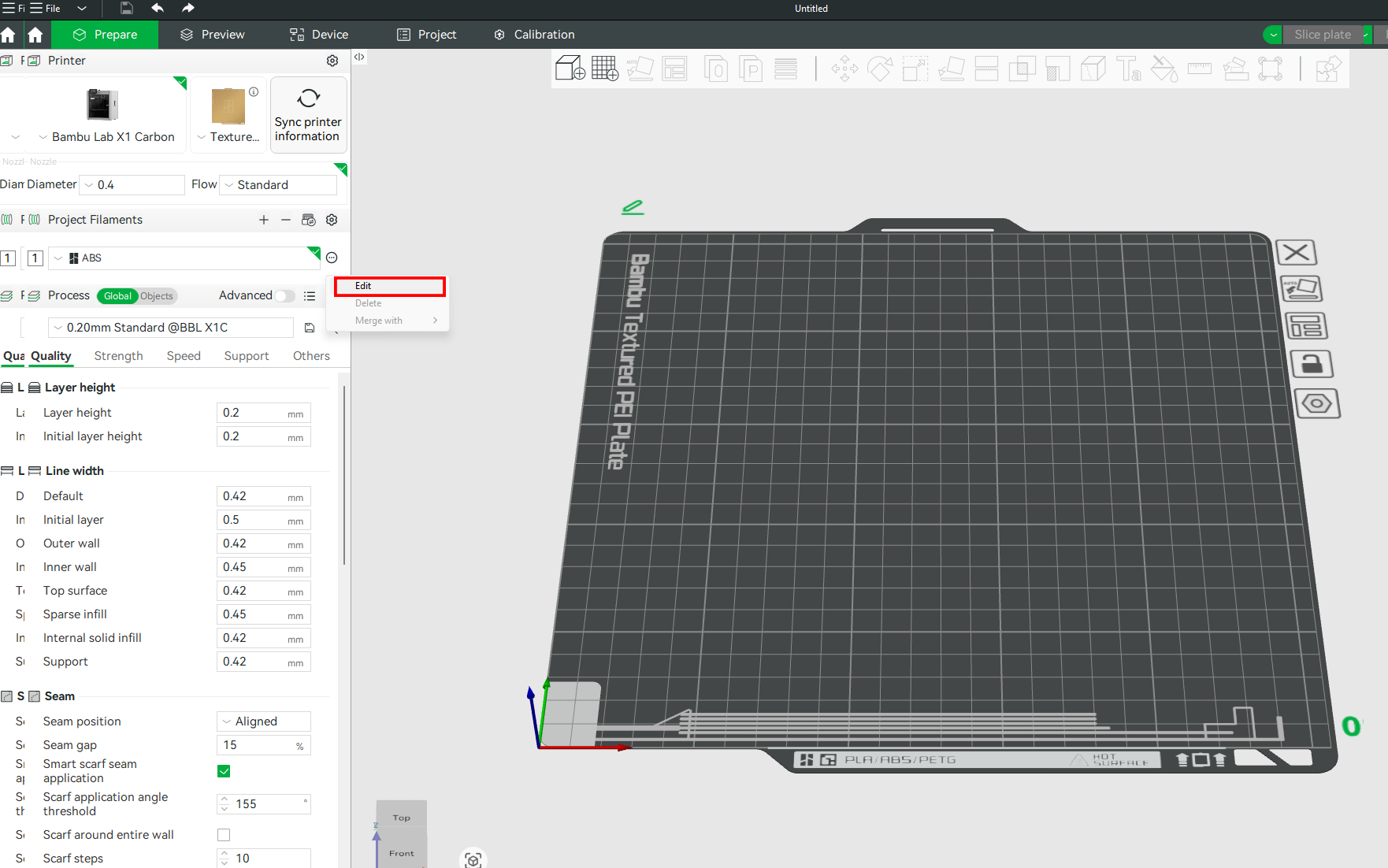
In the Filament Settings window that launches, you will be able to see the Shrinkage setting.
This setting change is only applied to a single filament, not a global adjustment. Remember to add the shrinkage parameter to each filament as needed.
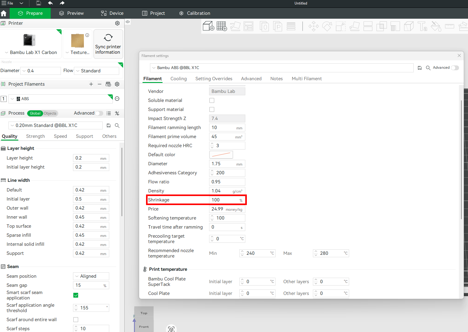
The shrinkage compensation is expressed as a percentage (%), with a default value of 100%. If you select the default value, it means that no scaling is applied by default. Your model will print at the original dimensions as designed in the slicer.
¶ Shrinkage Compensation Formula
To know the value to put in the Shrinkage section, take the measured dimension of the print, then divide by the expected dimension, and multiply by 100%.
Shrinkage Compensation (%)=(Measured Dimension / Designed Dimension)×100.
- Measured Dimension: The actual value you get from the printed part using calipers.
- Designed Dimension: The original size of your 3D model.
For example, you designed a cube that measures 20mm; after 3D printing and measuring, you find that the size is 18mm. Therefore, the shrinkage value will be (18/20) × 100 = 90%. We will then place this value in the Shrinkage section, and it will automatically scale future models up accordingly. After applying the new changes, ensure that you save the profile by clicking the save icon in the top right section.
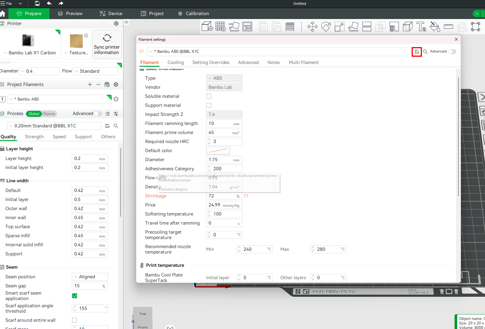
Once saved, the shrinkage factor is applied every time you use that filament.
¶ How to Test Shrinkage
You don't need to 3D print your intended file for testing purposes. Instead, you can simply print a standard cube (e.g., 20 mm x 20 mm x 20 mm or 100 mm x 100 mm x 100 mm flat square). To do, in Bambu Studio, right-click on the workspace, click Add Primitive, then choose Cube.
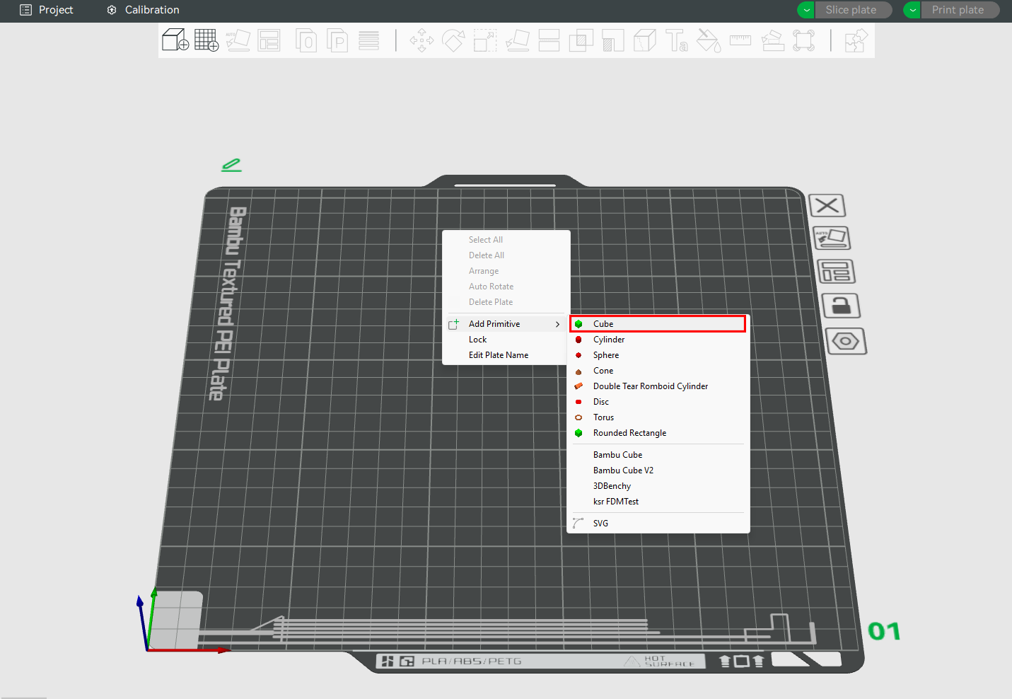
You can proceed to slice and 3D print as is, but if you want to specify the size, click on the Scale tool and enter the X, Y, and Z values in the size section. If a Uniform scale is applied, you simply put one value, and the rest will be applied automatically.
Slice and 3D print the file.
Then, use calipers to measure the dimensions after the sample has cooled.
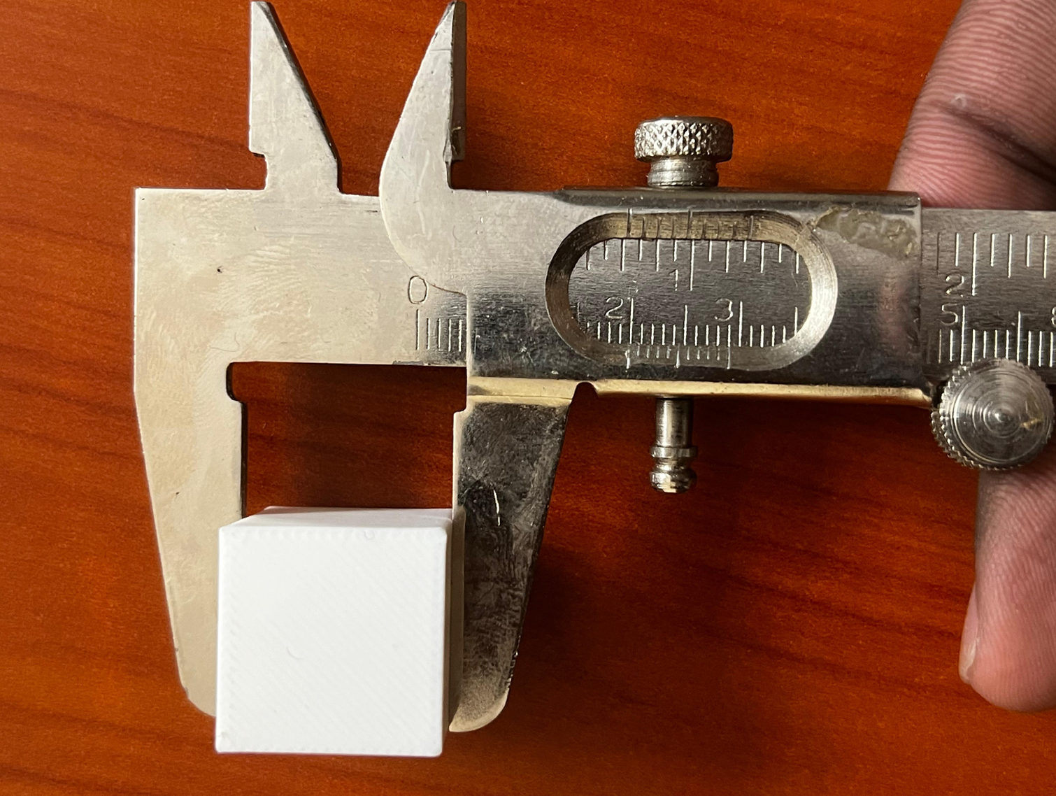
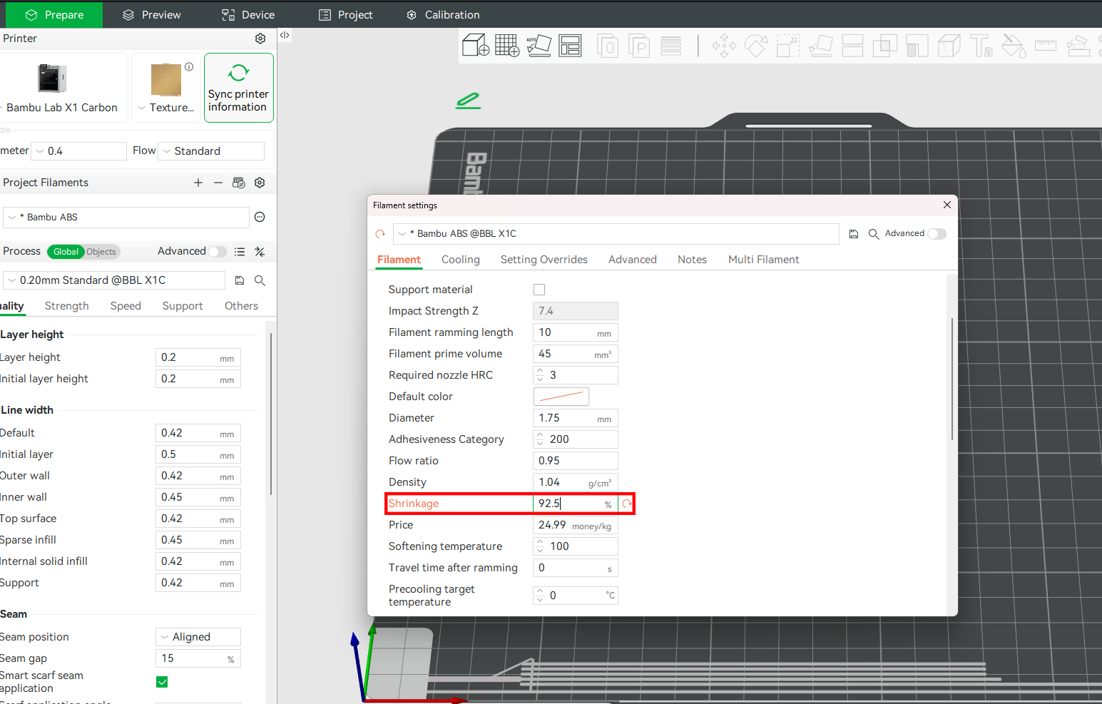
The cube we 3D printed measured 20 mm x 20 mm x 20 mm. However, after measuring the cube, I found it to be 18.5 mm in each dimension. We can then calculate the shrinkage percentage using the formula we highlighted above. That is (18.5/20)x100%= 92.5%.
We will then input the value into the Shrinkage section of the filament profile in Bambu Studio.
Next, we will save the settings, slice the cube, and 3D print it again. After 3D printing and re-measuring, the dimensions were 19.7 mm. This is not far from the intended value, considering the error margin of the vernier caliper I was using. However, to get much closer to 20mm, we will re-enter the value in the Shrinkage settings and repeat the process.
Remember, the Shrinkage setting adjusts the scaling of the model’s outer dimensions (X and Y), but it does not affect the size of internal features such as holes and contours. If you need to correct the dimensions of these, use the X-Y Hole/Contour and Auto-Circle Holes Compensation setting instead. Below, we provide a detailed description.
¶ X-Y Hole/Contour Compensation Function
¶ X-Y Hole Compensation
If you have ever 3D printed a model like bolts and nuts that are supposed to slide in smoothly, and you later realize they don't fit together or match, it can be frustrating. During the design phase, everything was okay, but later, you realized the holes were just too small and that you would need to put a lot of effort into making them fit. This isn’t a design flaw. It’s a common issue caused by shrinkage.
The XY hole compensation setting in Bambu Studio lets you fix this issue directly in your slicer without constantly modifying the file in a CAD software. It automatically increases the diameter of horizontal internal holes to compensate for the natural reduction in size caused by material shrinkage and over-extrusion. Without this setting, you will often encounter holes that are smaller than designed, pegs that don’t fit into their sockets, or even mounting holes that require drilling after printing.
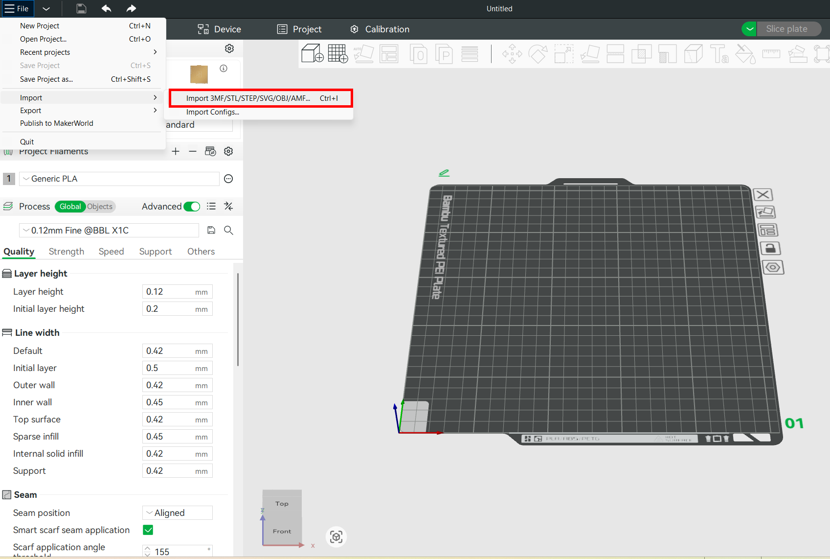
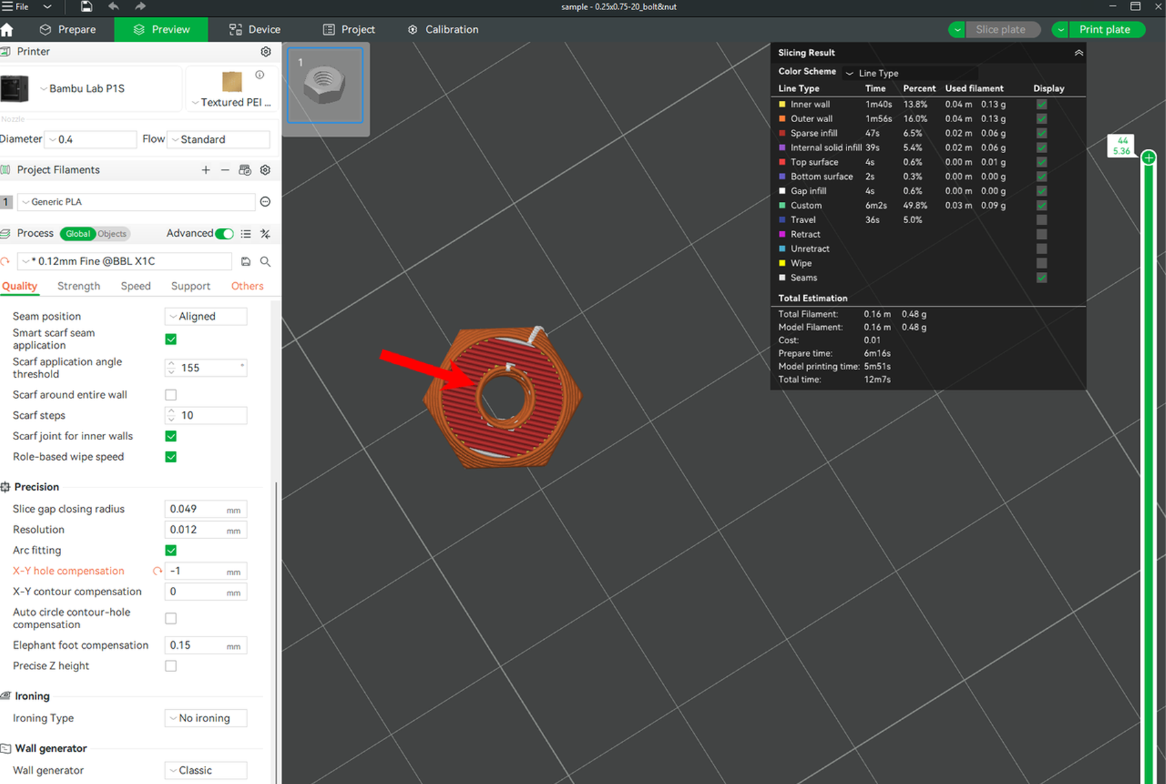
To describe how XY hole compensation works, let's import a 3D model to Bambu Studio by creating a new project, then go to File > Import.
If the file is in MakerWorld, you can open it directly in the software by clicking Open in Bambu Studio.
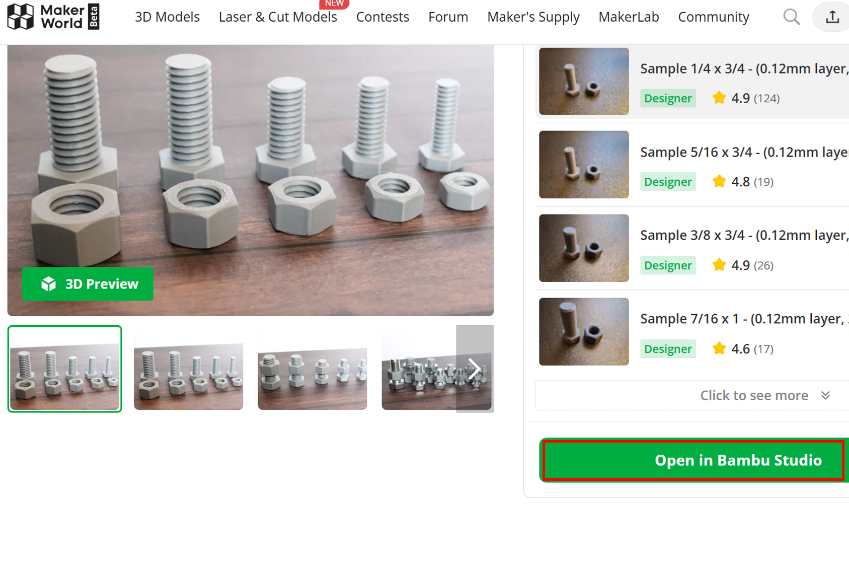
We are going to use the Imperial bolts and nuts by Makidev on Makerworld for demonstration. After importing, click on it so it's highlighted. Then, go to the Quality tab in the left section of the menu bar, after clicking on Objects settings. You will then see X-Y hole compensation.
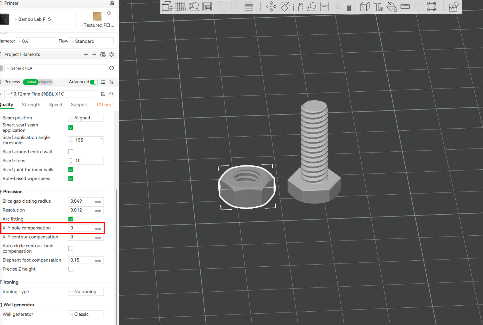
The X-Y hole compensation is specified in millimeters, with a default value of 0. You can enter a positive value to increase the hole size slightly. If you are using PLA, you can start with a 0.05mm value, 0.1mm for ABS/PETG, and 0.15mm for Nylon. This instructs the slicer to offset the inner perimeter of holes outward by the value entered in the X-Y axis. If you enter a negative value, the hole will be shrunk in the XY plane by the set value. The image below shows the hole before adjusting the X-Y plane.
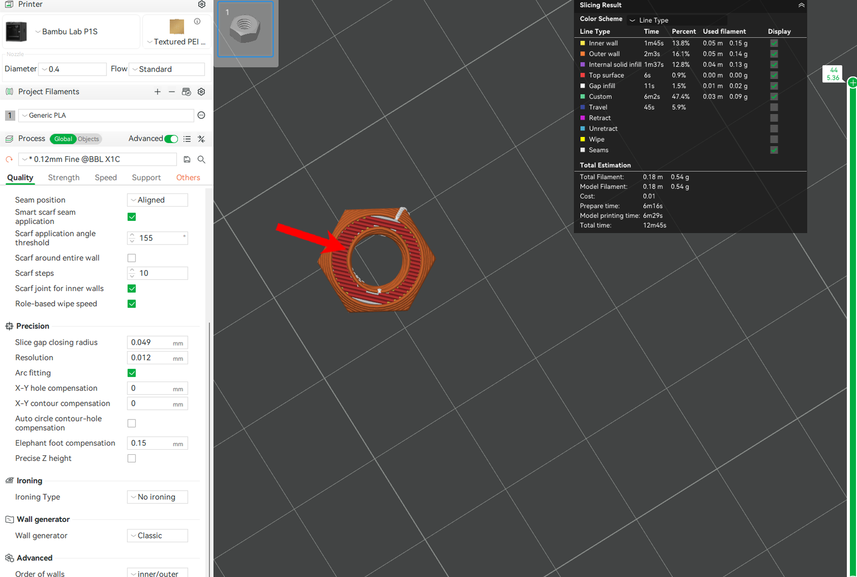
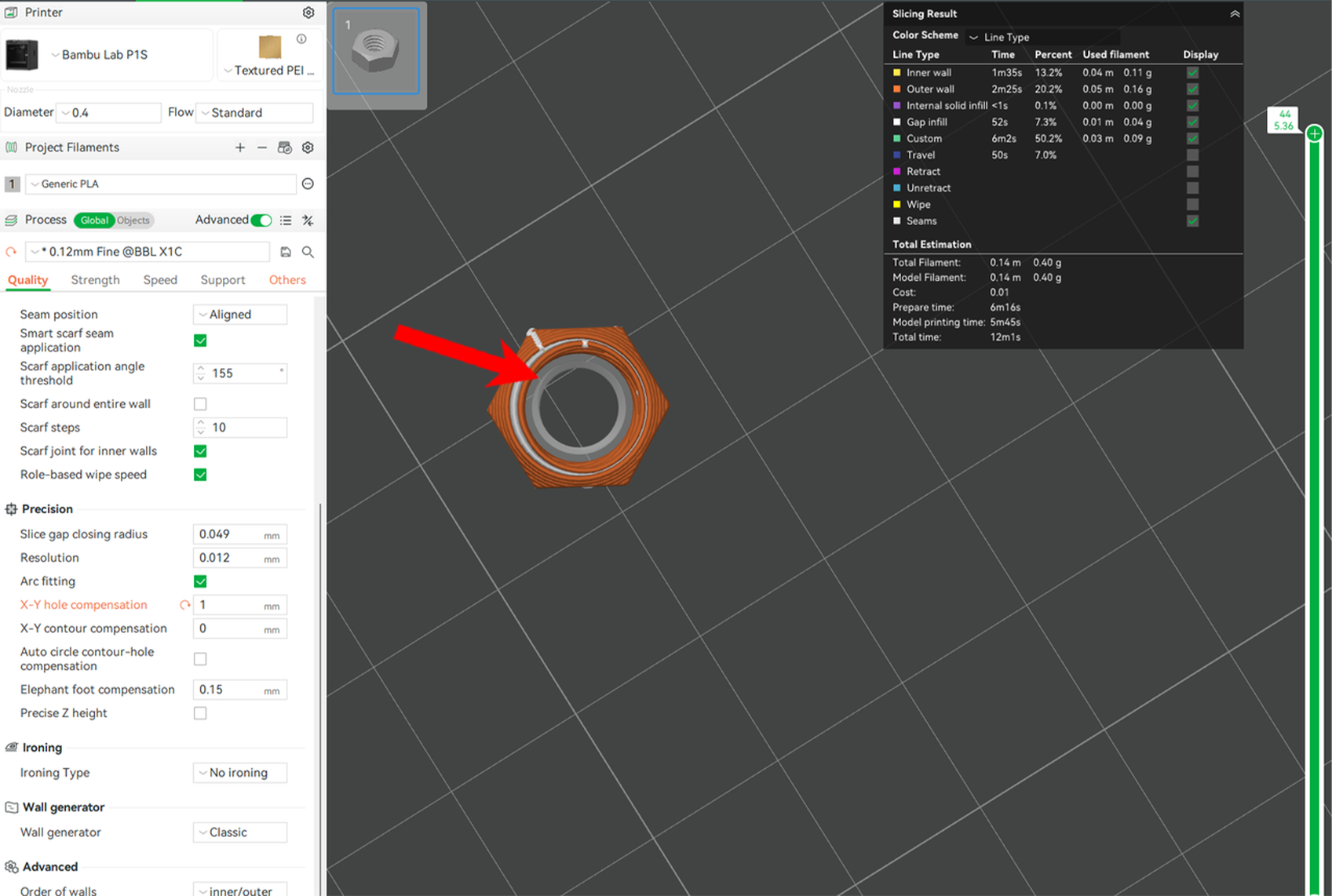
After adding an X-Y hole compensation of 1, the size of the hole increased, as shown below, but the outer section remained unchanged.
Using a negative value reduces it, as shown below.
When addressing shrinkage issues in 3D prints, particularly for holes that become too small, it’s essential to use a positive value to instruct the slicer to adjust the internal perimeters of holes outward, thereby increasing their diameter in the X-Y plane. This is particularly important for parts that require precise fits, where even a slight dimensional error can make assembly difficult.
On the other hand, a negative value is generally used to create tight or interference fits and is not a solution for holes that come out undersized due to cooling contraction or extrusion behavior.
¶ Practical Example
As a rule of thumb, it's important to start with a small positive compensation and 3D print a test model to see what it looks like. Once you find a value that consistently gives you accurate results for your filament and printer, you can save it as part of a custom profile in Bambu Studio for future prints.
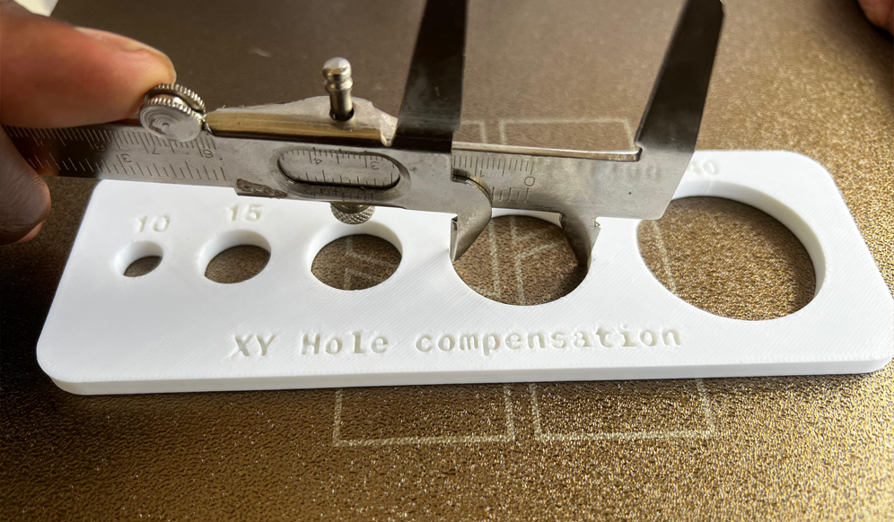
X-Y Hole compensation design by Mattiamagno_3D found in MakerWorld is a good example of a test model that you can 3D print.
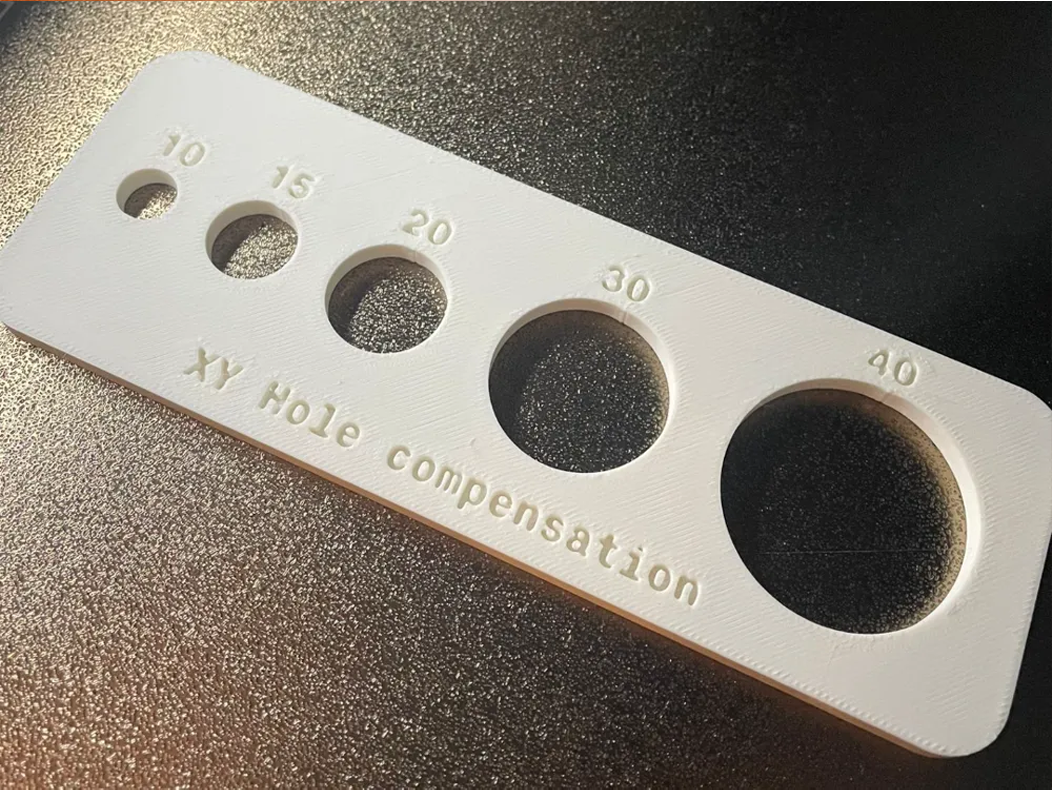
To use the test print above, 3D print it and measure each hole using a caliper.
For each of the hole above, after measuring, I got the following values.
| Hole Label (mm) | Measured Diameter (mm) |
|---|---|
| 10 | 10.6 |
| 15 | 15.55 |
| 20 | 20.58 |
| 30 | 30.55 |
| 40 | 40.5 |
The next step is to calculate the errors. We shall subtract each measured value from the intended design value.
| Hole Label | Intended | Measured | Error (mm) |
|---|---|---|---|
| 10 | 10.00 | 10.6 | -0.60 |
| 15 | 15.00 | 15.55 | -0.55 |
| 20 | 20.00 | 20.58 | -0.58 |
| 30 | 30.00 | 30.55 | -0.55 |
| 40 | 40.00 | 40.5 | -0.50 |
You’ll typically find that the error value is almost the same across all holes. The next step is to take the average of all the errors. To do this, add all of them, then divide by 5.
Average Error=−0.60+(−0.55)+(−0.58)+(−0.55)+(−0.50)/5= -0.556 mm.
To obtain the XY hole compensation value, we shall divide the obtained value by 2. -0.556/2 = -0.278 mm. The reason we are dividing by 2 is that a hole has two sides - a left and a right (or top and bottom), depending on its orientation. If a circular hole is undersized, say by 0.6 mm total, that error is distributed equally across both sides. We shall then put the value we got in the XY hole compensation section.
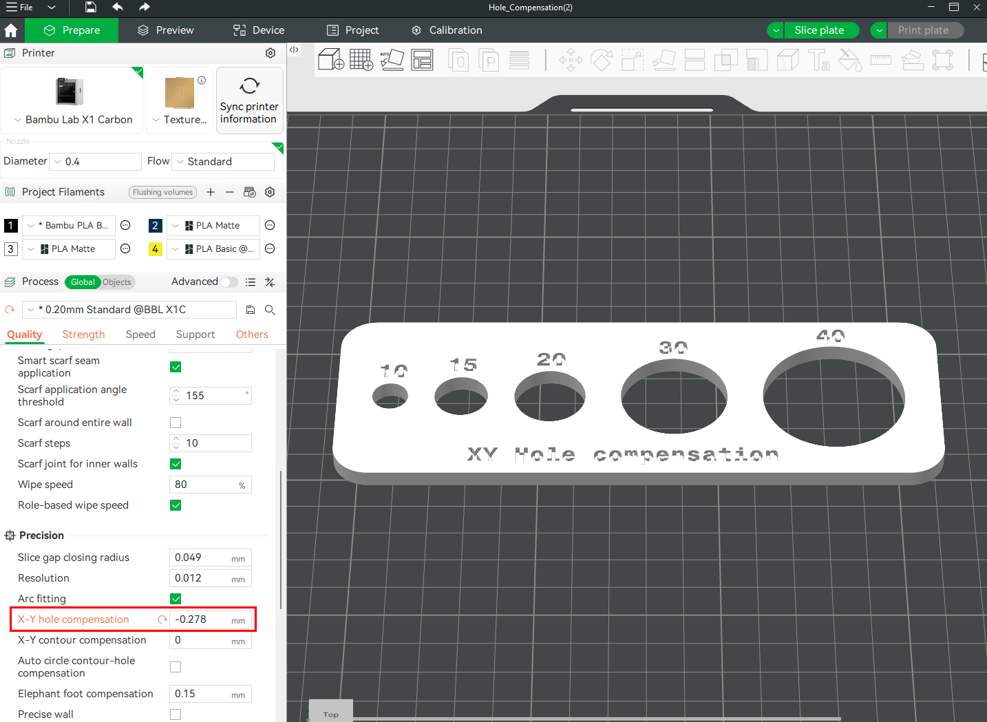
Take that average error, divide it by two, and enter the result as the value for the X-Y Hole Compensation setting. Reprint the model and remeasure the holes to confirm that the dimensions now match your original design more accurately.
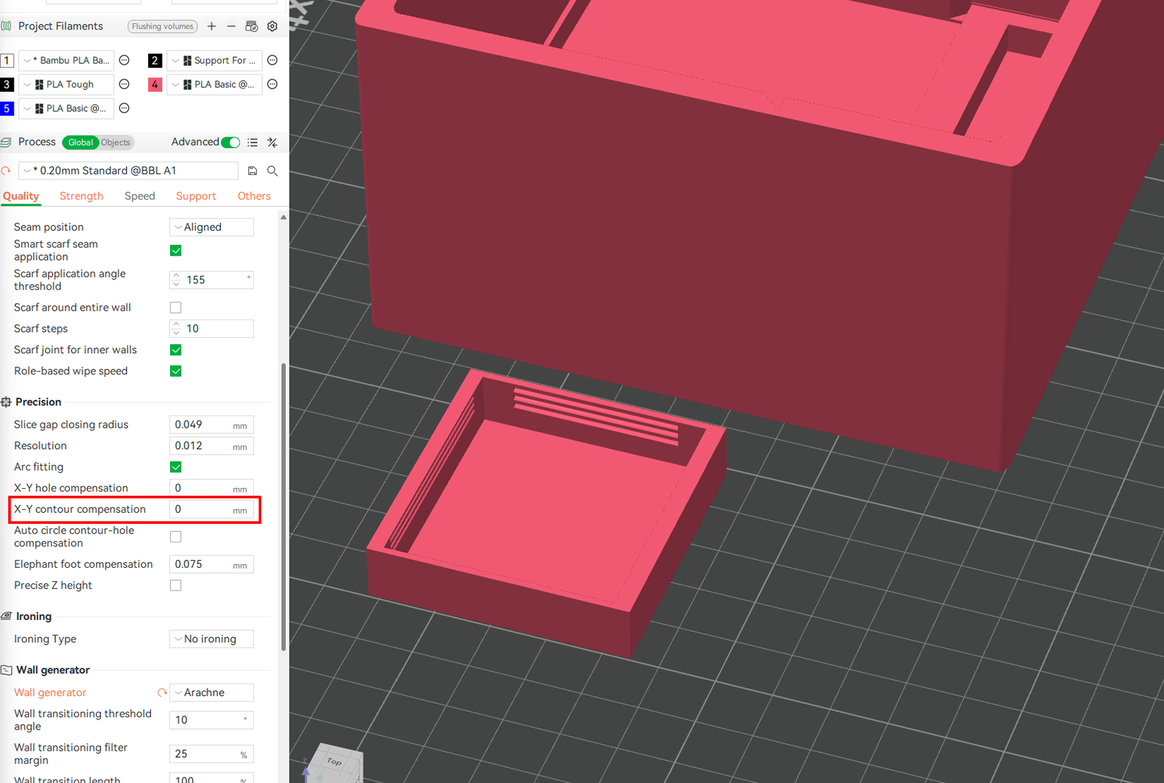
¶ X-Y Contour Compensation
Just below X-Y hole compensation is the X-Y contour compensation. Unlike X-Y hole compensation, which helps fix undersized holes, X-Y contour compensation is your go-to solution when external features or outlines are affected, such as walls, flanges, slots, or any mating edges. It's found just under the X-Y hole compensation.
To illustrate how it works, let’s consider a 3D model, such as the Anti-Boredom Mini Game Box by LeeBob, which can be found on MakerWorld. Each side is designed to fit snugly into the larger box. After 3D printing, you measure the part and discover that the sides have shrunk slightly from the intended size. This shrinkage affects the entire perimeter, which is especially problematic when the sides don't fit correctly into the slots. To prevent this, you can adjust the X-Y Contour Compensation setting.
This setting adjusts the position of the outermost perimeters of your model in the horizontal plane. Entering a positive value expands the external shape outward, making your printed part slightly larger in X and Y. A negative value contracts it inward, making the print smaller. This tool is useful when a printed object consistently comes out smaller than intended due to material shrinkage or slight extrusion inconsistencies.
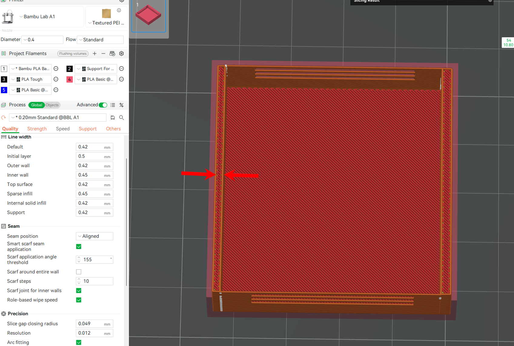
In the example below, the file looks like this after slicing and previewing.

After applying a value of +1, you will see that the size of the walls has increased, as shown below.

Entering a negative value will decrease them.
Generally, X-Y contour compensation is the ideal way to correct for dimensional loss on the outer surfaces of your model due to shrinkage. As you adjust the contour path directly in the slicer, you can maintain your original design dimensions and save yourself hours of guesswork and post-processing. Use it when the external size of your parts is smaller than expected, and when 3D printing parts that need to align or slide together, like cases, brackets, or enclosures.
Check out the XY Hole/Contour compensation wiki to learn more in detail about how it works.
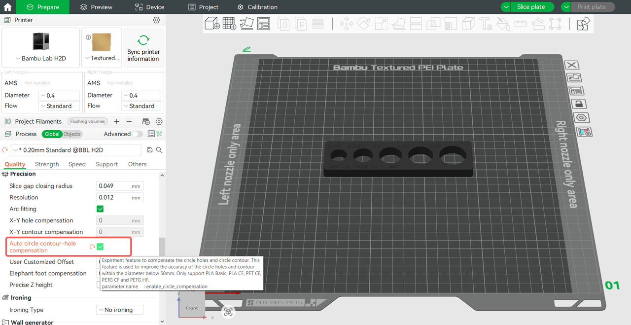
¶ Auto Circle Holes-Contour Compensation
This feature is designed to improve the dimensional accuracy of circular holes in 3D prints, especially for assembly purposes. It works by standardizing the printing speed and applying specific compensation values based on the material used, helping to counteract the shrinkage that naturally occurs during printing. It's specifically perfect for circular holes or shafts that lie on the horizontal plane and have a diameter of 50 mm or less. To use it, go to the Process > Quality section in Bambu Studio before slicing, and enable the Auto Circle Holes-Contour Compensation option.
Ensure you select the correct filament profile, slice your model, and then proceed to print. This compensation method enhances the dimensional accuracy of circular holes and shafts, facilitating a snug fit with standard components such as bearings or other 3D-printed parts.
Auto Circle Holes- Contour Compensation is primarily optimized for H2D and certain supported filaments. For other 3D printers, the function will use general compensation settings, which may still improve accuracy but might not deliver optimal results. In such cases, it's not necessary to enable this feature.
For more details, check out the Auto-Circle Holes-Contour Compensation wiki.
Besides the above, another way to avoid shrinkage in 3D prints is by using fiber-reinforced filaments, such as those infused with Carbon Fiber or Glass Fiber. These filaments are made by combining a base polymer, usually PLA, PETG, or Nylon, with fibers that improve dimensional stability during printing and cooling by reducing thermal expansion. Standard thermoplastics tend to shrink significantly as they cool from extrusion temperatures to room temperature; however, these materials act as reinforcement, restricting the extent to which the plastic matrix can contract.
¶ End Notes
We hope our guide was helpful. If you have any questions or concerns about the process, please contact our customer service team. We're here to assist you.
Click here to open a new ticket in our Support Page.
We will do our best to respond promptly and provide you with the assistance you need.