¶ What does this feature do?
In the additive manufacturing process of 3D printing, it is often encountered that the actual size of the printed parts deviates from the ideal size, which leads to difficulties in assembling the shafts and holes, whether it is between printed parts or with the actual object. The factors that affect this size change are not only the motion accuracy of the printer, but also the thermal shrinkage and deformation of the material. This mechanism involves complex material thermoforming problems, and this function is dedicated to solving the most common and simple problem of circular hole and shaft assembly. For 3D printing of circular holes and shaft sizes of different materials, slicing algorithms will compensate accordingly, thereby achieving printing circles with smaller deviations and precision assembly with smaller tolerances.
¶ Compensation principle
Studio's slicing algorithm will identify circular hole/shaft features that meet the criteria (only for complete circles on the horizontal plane, semicircles or circles in the vertical direction will not be compensated), and provide reasonable size compensation based on detailed test data. In this compensation process, the slicing algorithm limits the print speed of the identified circular features, making it uniform (print speed 200mm/s). At the same time, ensure that the cooling system is turned on to the maximum power during the printing process, providing a stable and efficient cooling rate of filaments. Under the premise of controlling the unified printing environment, Studio will modify the size of circular features based on the compensation model formula. The specific parameters in the compensation model formula will vary depending on the filament, and we have already built them into the slicer. You do not need to make any additional adjustments.
¶ How to use this feature?
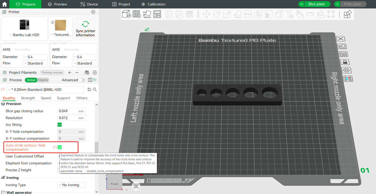
Firstly, this function is only applicable to complete circular holes/shafts on a horizontal plane, with a diameter size within 50mm. Therefore, if the model you are printing has such circular features and its size is important for assembly, you can select "Auto Circle Holes-contour Compensation" in the Process—Quality before slicing to enable this function. Then select the corresponding filament, slice it, and send the print task to obtain a model with a more accurate circular hole size accuracy.
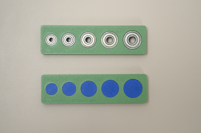
The precision of the model's circular holes and shafts printed through this compensation is higher, enabling compact assembly with standard components (such as bearings) or other printed parts.
¶ Matters needing attention
-
Currently, this feature is only compatible with some Bambu Official filaments, and more applicable filaments will be added in the future.
-
This feature is designed to compensate for default settings (default sparse infill, etc.). However, it will have a reduced effect on extreme settings and placements (such as 100% infill, circular shafts placed too close, etc.).
-
This feature will only apply to Bambu official dry filaments. For filaments that are damp, the size compensation effect will be reduced (dampness changes the filament's deformation and shrinkage properties). In addition, for non-Bambu official filaments, this feature may not achieve the expected effect.
-
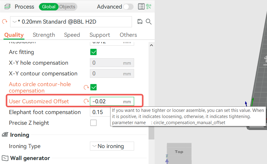
If the filament drying effect is insufficient, the Auto Circle Contour-Hole Compensation feature may still not achieve the tightest fit. Based on our experience, under the same parameters, dry filament results in a looser fit, and moist filament results in a tighter fit. In this case, you can try manually adjusting the compensation parameters. Enter the compensation value in the "User Customized Offset" section in Studio: positive values make the assembly looser, while negative values make the assembly tighter. You can adjust the value based on your drying conditions, and we recommend using a step value of 0.02mm for fine-tuning.
-
This feature is only applicable to complete circles (non-ellipses) on the horizontal plane, and circles do not interfere with each other. Other situations will not be recognized and compensated by features.
-
This compensation feature will automatically use the scarf seam for the wall of the shafts and hole, which can effectively hide the seams on the circular surface and ensure a more accurate circle size. You can refer to the wiki for more information about scarf seams: Seam settings.