¶ MC Board of P series
MC stands for Machine Controller, which is the unit that controls all the moving parts of the printer.
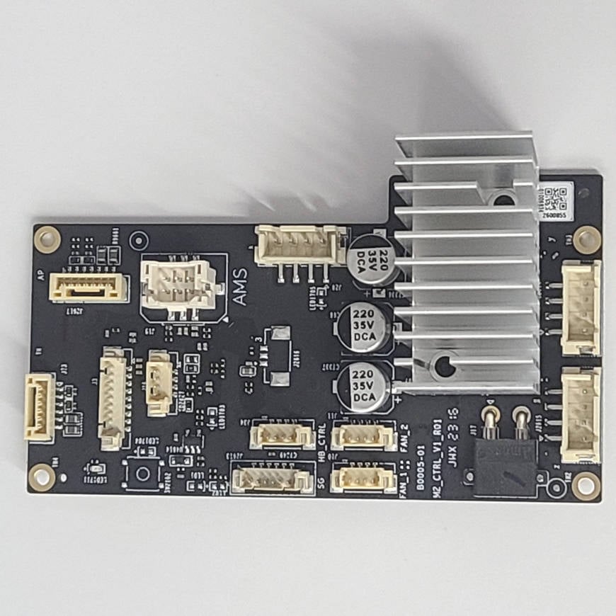
There are differences in the heatsink of the MC boards for P1P and P1S, but the boards are the same.
 |
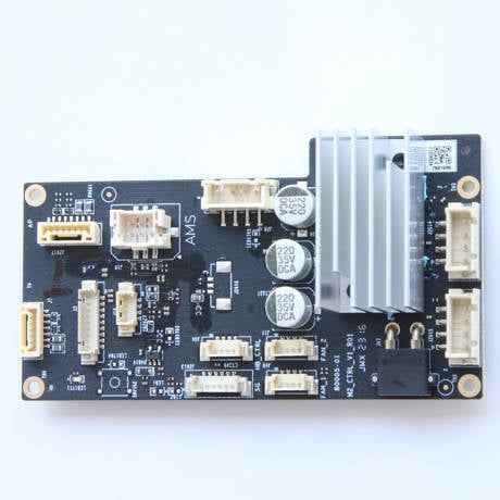 MC board for P1S |
The P1P board has a vertical orientation heatsink to help with natural convection cooling when used without a fan, while the P1S heatsink has a horizontal heatsink orientation for side MC Fan cooling. Both heatsinks will perform similarly with a fan on the side.
Please note!
1. If you receive the MC board in the status as shown in the picture below (without thermal grease), please refer to the Supplement 1 of this wiki to reuse the original heat sink.
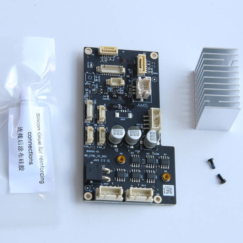
2. If you want to exchange the heat sink from the original P1S MC board for the new MC board, please refer to the Supplement 2 of this wiki to reuse the original heat sink.
¶ Tools
H2.0/1.5 hex key
Tweezers
Silicone glue
¶ Safety Warning
IMPORTANT!
It's crucial to power off the printer before performing any maintenance work on the printer and its electronics, including tool head wires, because leaving the printer on while conducting such tasks can cause a short circuit, which can lead to additional electronic damage and safety hazards.
When you perform maintenane or troubleshooting on the printer, you may be required to disassemble some parts, including the hotend. This process can expose wires and electrical components that could potentially short circuit if they come into contact with each other or with other metal or electronic components while the printer is still on. This can damage the electronics of the printer and cause further damage.
Therefore, it's essential to switch off the printer and disconnect it from the power source before doing any maintenance work. This will prevent any short circuits or damage to the printer's electronics. By doing so, you can avoid potential damage to the printer's electronic components and ensure that the maintenance work is performed safely and effectively.
If you have any concerns or questions about following this guide, open a new ticket in our Support Page and we will do our best to respond promptly and provide you with the assistance you need.
¶ Remove the faulty MC board
¶ Step 1 - Remove the excess chute
Refer to the related contents of the Excess chute (For P1P) & Metal rear panel replacement for P1S to remove the rear panel and the excess chute.
¶ Step 2 - Disconnect the cables
To disconnect all the cables from the MC board, start by removing the heat bed signal cable. Keep in mind that this cable may be fixed in place with silicone glue, so it may need to be cleaned before it can be easily removed. Once the heat bed signal cable has been removed, proceed to disconnect any remaining cables from the MC board.
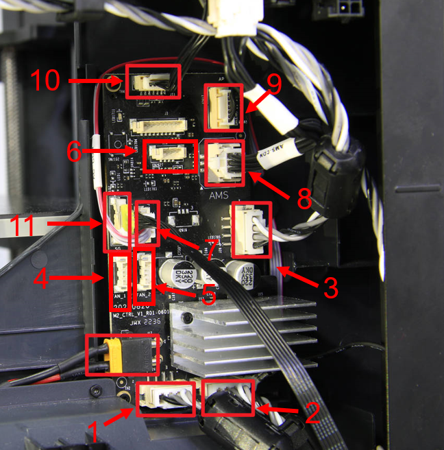
| NO. | Connect object | NO. | Connect object | NO. | Connect object |
| 1 | Motor Z | 5 | Auxiliary part cooling fan | 9 | AP main board(power and communication cable) |
| 2 | The right motor (view from the rear) | 6 | MC board fan | 10 | TH board(power and communication cable) |
| 3 | The left motor (view from the rear) | 7 | MC board to AC board connecting cable | 11 | Heat bed (Communication cable) |
| 4 | The chamber temperature regulator fan | 8 | AMS interface board |
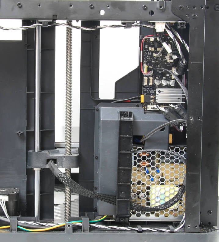
¶ Step 3 - Remove the MC board
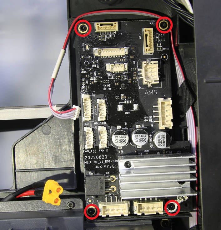
To remove the MC board, use an H1.5 hex key to unscrew the four screws that hold it in place. Once all the screws have been removed, the MC board can be lifted out.
¶ Install the new MC board
¶ Step 1 - Install the MC board
| To install the MC board, place it on the inner shelf and secure it with four screws. |
Pay particular attention to the screw in the lower right corner, as it will also be used to fix the ground cable in place. Once all the screws are tightened, the MC board should be firmly secured to the inner shelf.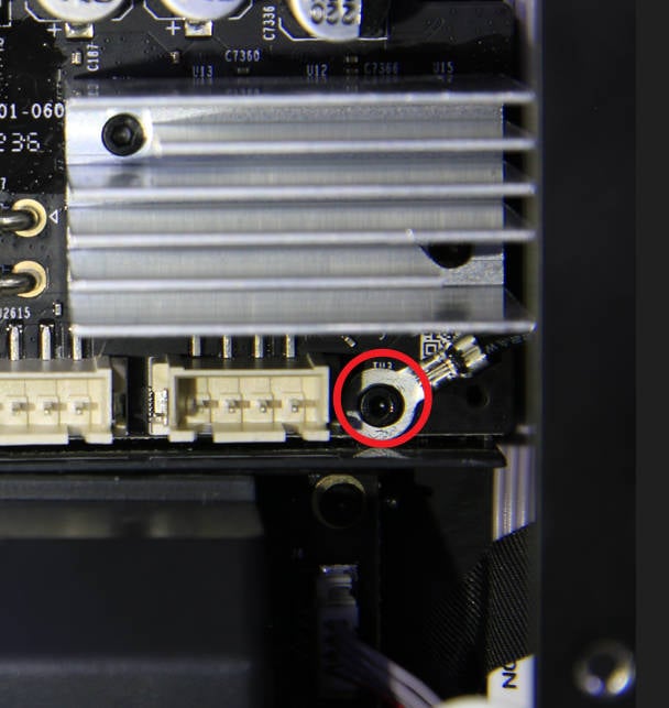 |
¶ Step 2 - Connect cables
To complete the installation of the MC board, start by connecting the heat bed signal cable. Once it is in place, apply silicone glue to reinforce the connection.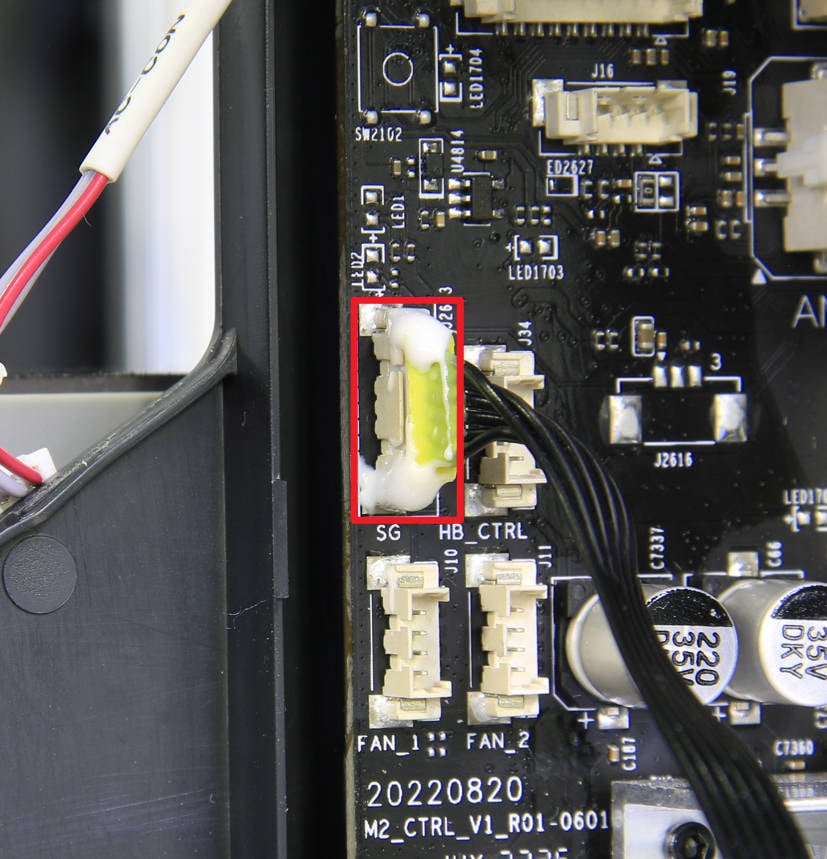 |
Then, connect the other cables to the MC board and make sure that all of the connections are secure. Once everything is in place, confirm that the connections are all in place.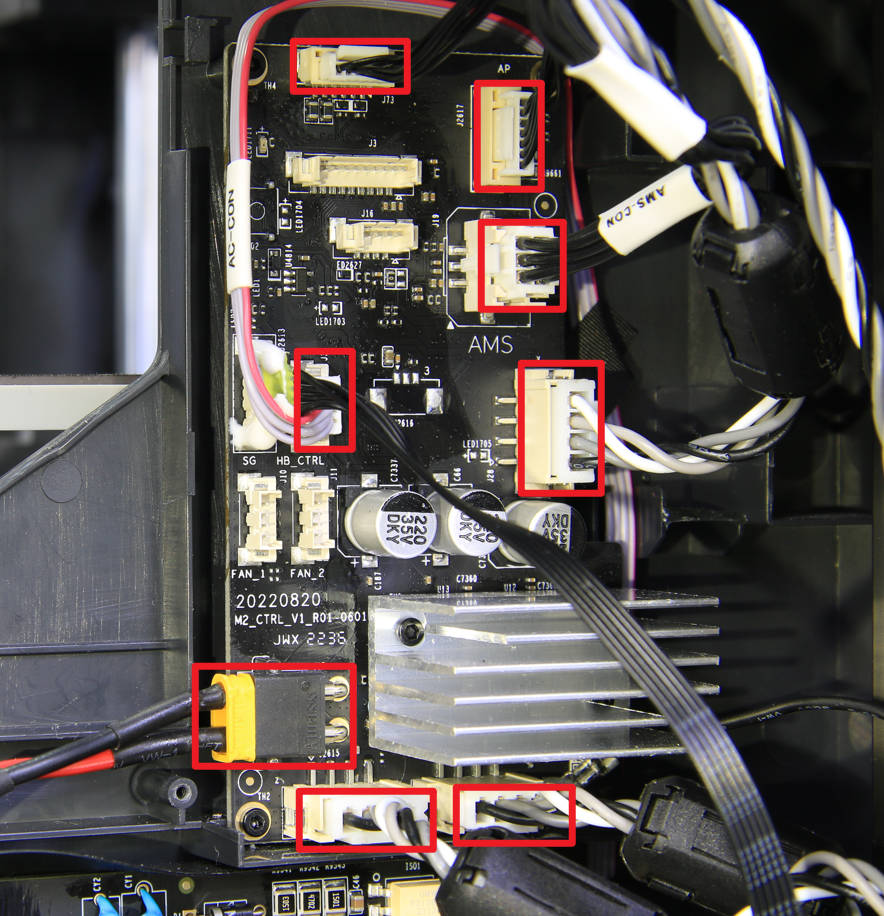 |
¶ Step 3 - Assemble the Printer
(For P1P) Refer to the related contents of the Excess chute to install the excess chute and the rear panel. 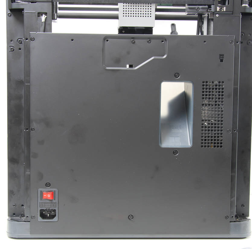 |
(For P1S) Refer to the related contents of the Metal rear panel replacement for P1S to install the rear panel. 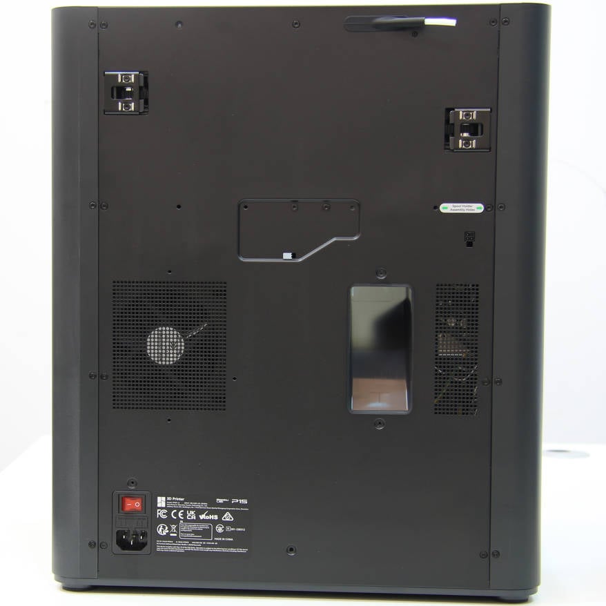 |
¶ Verify the functionality
To finish the setup of the printer, connect the power cord cable. Then, turn on the printer and run the device calibration process. If the calibration is successful, the operation has been completed successfully.
¶ Supplement 1_Reuse the heat sink of P1P
¶ Step 1 Remove the heat sink from the faulty MC board
Remove 2 screws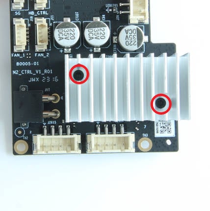 |
Separate the heat sink from the faulty MC board, do not clear the thermal grease from the heat sink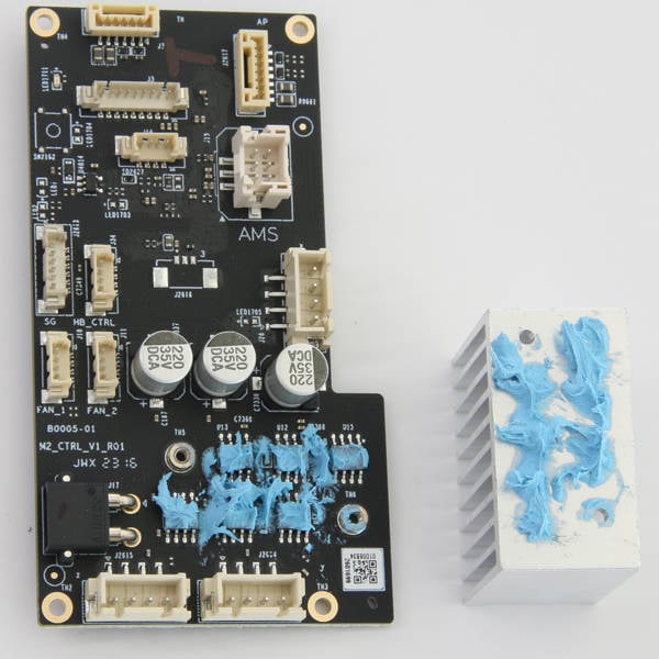 |
¶ Step 2 Install the original heat sink to the new MC board
Tear off the sealings from the 2 studs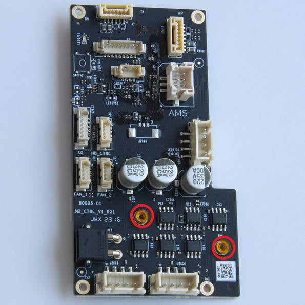 |
Install the heat sink (with thermal grease) to the new board and lock in 2 screws. |
¶ Apply the thermal grease to the new board if you get the thermal grease
The thermal grease (Blue)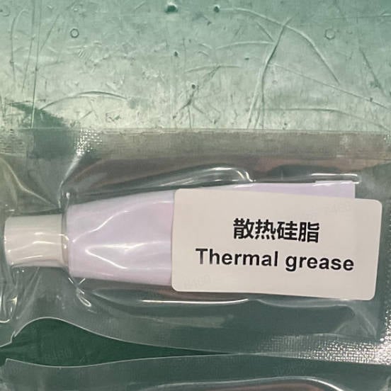 |
Apply thermal grease to the driver chips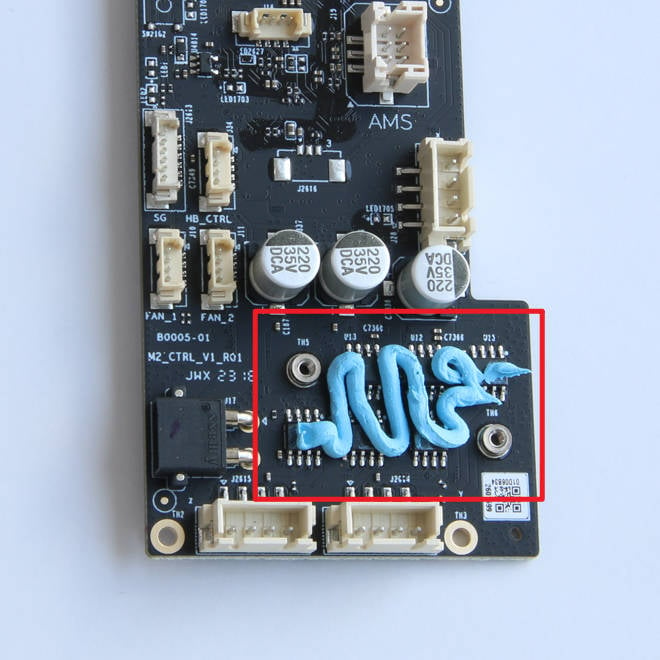 |
¶ Supplement 2_Reuse the heat sink of P1S
¶ Step 1 Remove the heat sink from the faulty MC board
Remove 2 screws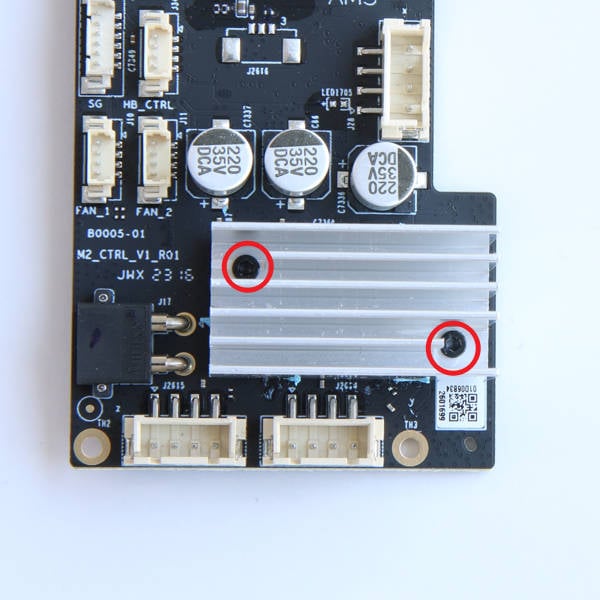 |
Separate the heat sink from the faulty MC board, do not clear the thermal grease from the heat sink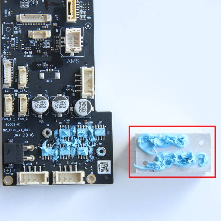 |
¶ Step 2 Remove the heat sink from the new MC board
| Remove 2 screws |
Separate the heat sink from the new MC board, there is no need to clear the thermal grease |
¶ Step 3 Install the original heat sink to the new MC board
Install the heat sink to the new board 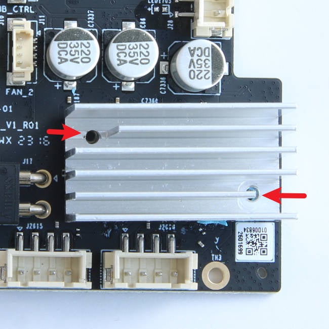 |
And then lock in 2 screws |
¶ Verify the Functionality
¶ Check the indicator lights on the control board
Normal State: the MC board flashes green once every 5 seconds
https://public-cdn.bblmw.com/wiki/video/P1-MC.mp4
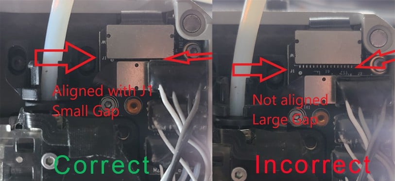
If the indicator light on the MC board is not flashing once every 5 seconds (for example, once every 30 seconds), please check whether the FPC cable is connected correctly.
¶ End Notes
We hope that the detailed guide we shared with you was helpful and informative.
We want to ensure that you can perform it safely and effectively. If you have any concerns or questions regarding the process described in this article, we encourage you to reach out to our friendly customer service team before starting the operation. Our team is always ready to help you and answer any questions you may have.
Click here to open a new ticket in our Support Page.
We will do our best to respond promptly and provide you with the assistance you need.