¶ Toolhead boards of P1P/P1S
The toolhead boards referred to here comprise three components: the TH board, the Extruder Connection board, and the TH board FPC cable connecting them.
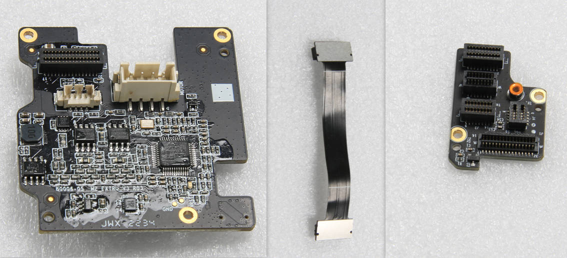
From left to right, the TH Board, TH Board FPC cable, and the Extruder Connection Board
You can purchase them at our store here:
TH Board - P1 Series
TH Board FPC Cable - P1 Series
Extruder Connection Board - P1 Series
¶ Safety Warning
IMPORTANT!
It's crucial to power off the printer before conducting any maintenance work, including work on the printer's electronics and tool head wires. Performing tasks with the printer on can result in a short circuit, leading to electronic damage and safety hazards.
During maintenance or troubleshooting, you may need to disassemble parts, including the hotend. This exposes wires and electrical components that could short circuit if they contact each other, other metal, or electronic components while the printer is still on. This can result in damage to the printer's electronics and additional issues.
Therefore, it's crucial to turn off the printer and disconnect it from the power source before conducting any maintenance. This prevents short circuits or damage to the printer's electronics, ensuring safe and effective maintenance. For any concerns or questions about following this guide, open a new ticket in our Support Page and we will do our best to respond promptly and provide the assistance you need.
¶ Tools
- H1.5 hex key
¶ Preparation
Unload the filament and power OFF the printer.
WARNING! Ensure that ALL hotend/toolhead changes are performed with the power OFF. Unplugging or reconnecting any of these connectors while the power is ON may result in a short circuit and cause permanent damage to the toolhead boards.
¶ Video guide
¶ Disassembly
¶ Step 1 - Remove the housing of the toolhead
Refer to this wiki guide The housing of toolhead to remove the toolhead housing.
Note: If you only need to remove the TH board, then it is sufficient to remove the rear housing of the toolhead.
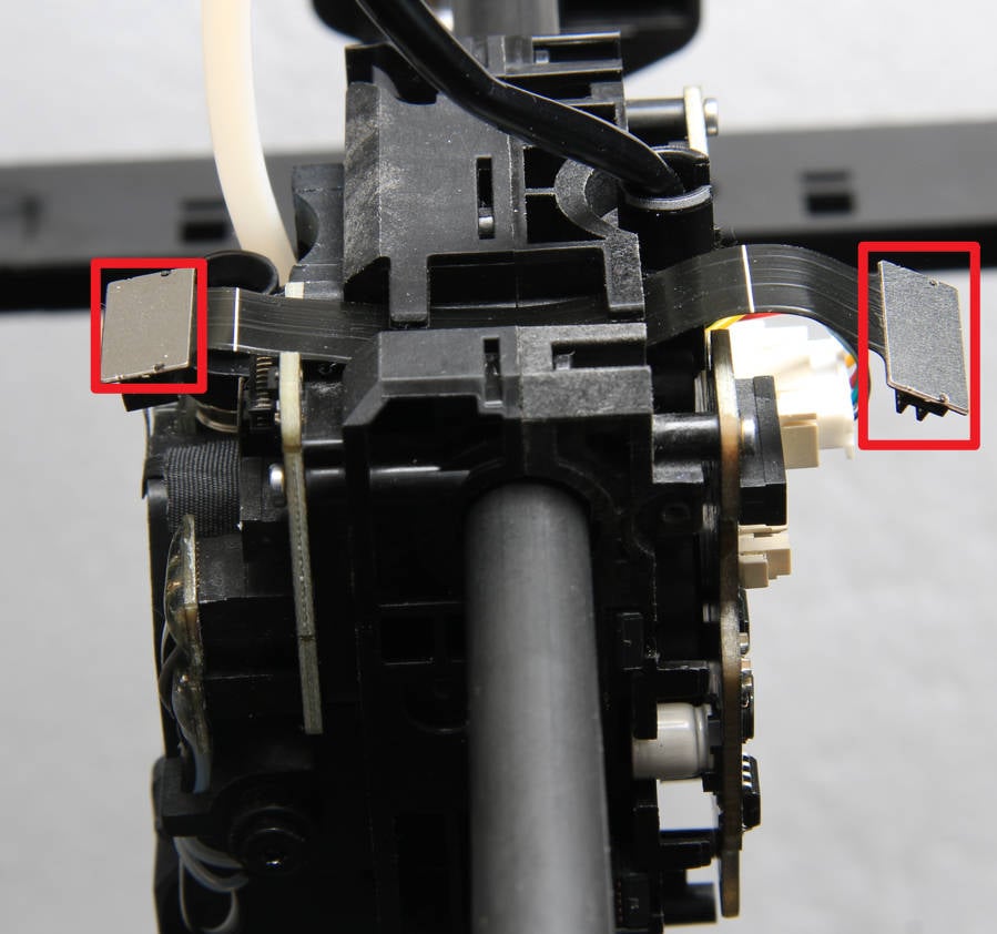
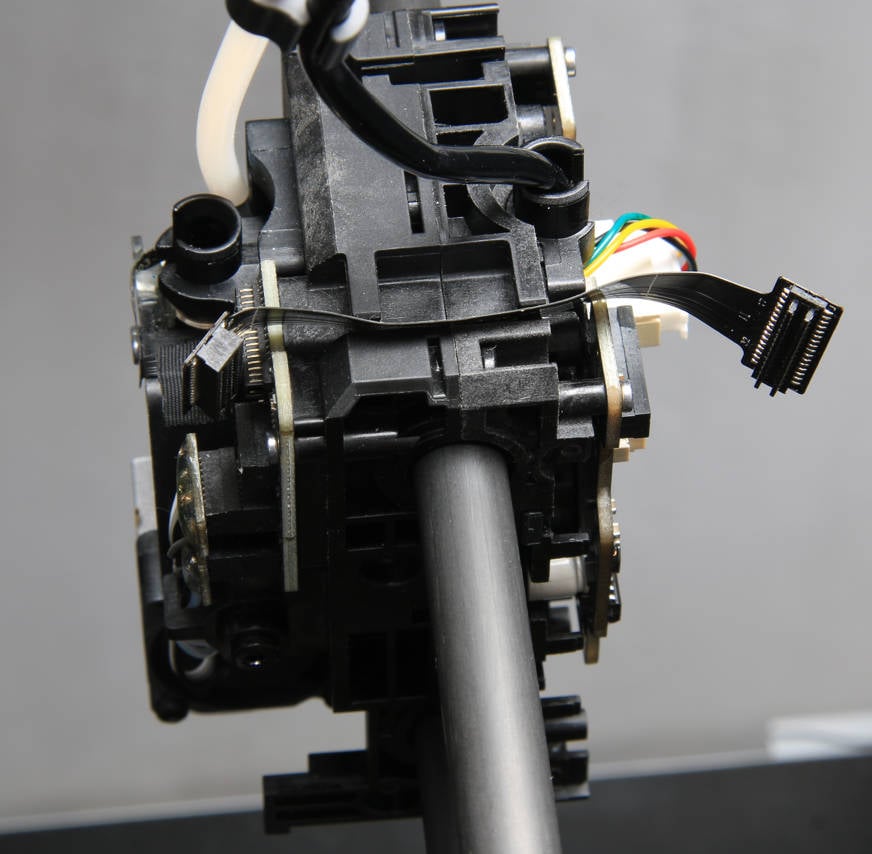
¶ Step 2 - Remove the FPC cable
Disconnect both ends of the FPC cable for removal.
 |
 |
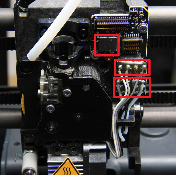
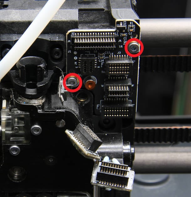
¶ Step 3 - Remove the connection board
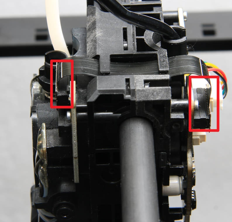
Disconnect the 3 cable connectors as shown below (the hall switch cable, hotend fan cable, and the heater cable). Proceed to remove the 2 screws using an H1.5 hex key and take off the connection board.
 |
 |
¶ Step 4 - Remove TH board screws
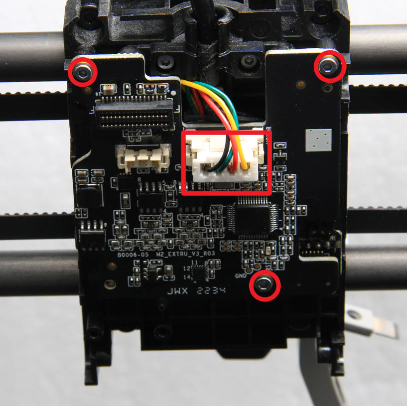
Disconnect the extruder motor cable and proceed to unscrew the 3 screws using the H1.5 hex key.
¶ Step 5 - Remove the TH board
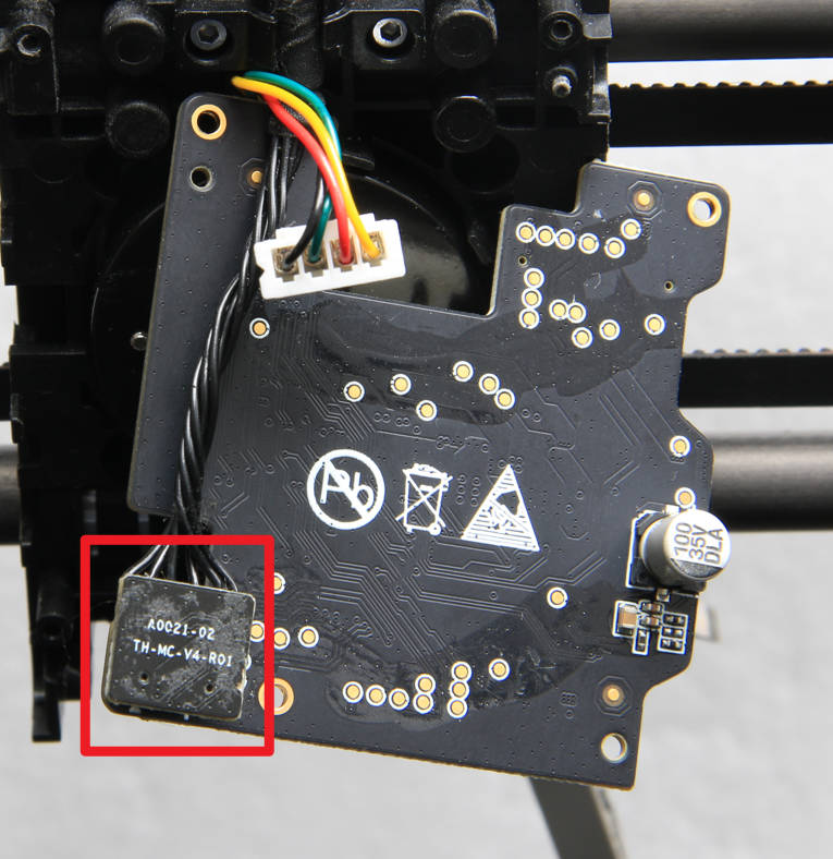
Flip the TH board over, remove the toolhead cable, and take off the TH board.
¶ Assembly
¶ Step 1 - Install the TH board
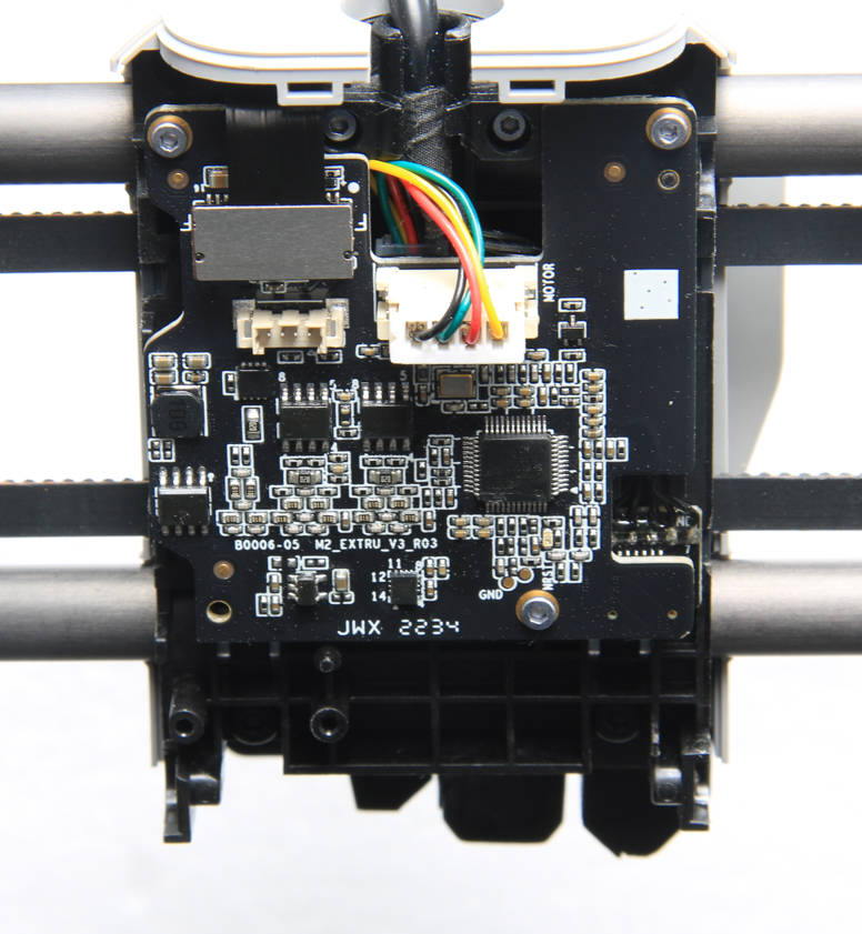
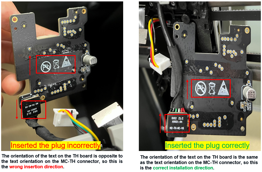
Reconnect the toolhead cable and install the TH board on the back cover of the carriage, ensuring the motor connector faces outward.
|
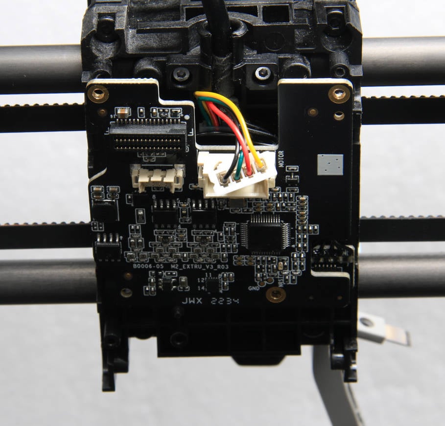 |
The MC-TH connector is directional, so ensure that the socket is inserted correctly. If inserted in reverse, it can cause a power short circuit, leading to the printer reporting an HMS error or being unable to power on properly.
¶ Step 2 - Secure the TH board
Secure the 3 screws back onto the board and reconnect the motor cable as shown below.

¶ Step 3 - Install the extruder connection board
Install the extruders connection board on the front cover of the carriage, secure the 2 screws, and then reconnect the heater cable, hotend fan cable, and hall switch cable.
|
|
¶ Step 4 - Install the FPC cable
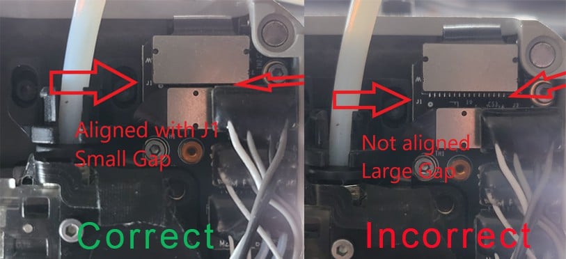
Install the FPC cable in the cable groove above the carriage, and connect the two ends to the FPC connectors of the connection board and the TH board, respectively.
|
 |
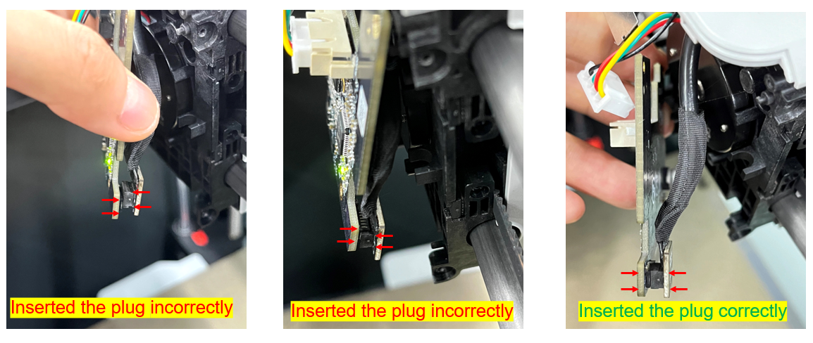
Please check if the FPC is correctly inserted as shown in the picture below:
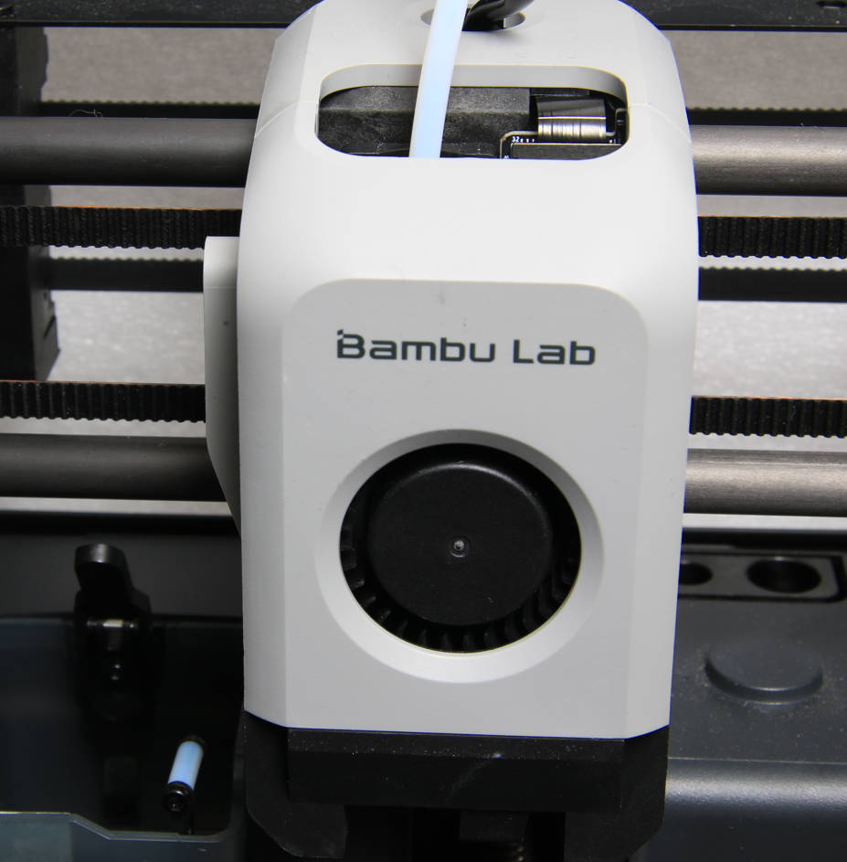
¶ Step 5 - Install the toolhead housing
Refer to The housing of toolhead to install the toolhead housing.
¶ To verify completion/success
1. Visually inspect the appearance to ensure that the joint positions are free of any misalignment and are flush.
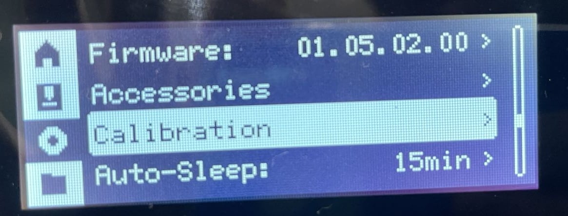
2. Power on the printer and initiate the device calibration process. If the calibration passes, the operation is successful.