¶ Toolhead Rear Housing and Middle Housing
|
|
You can purchase them at our store here:
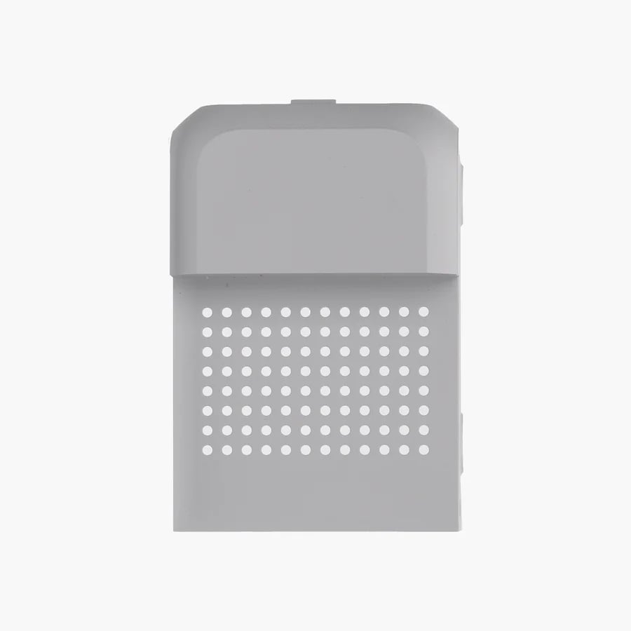
Toolhead Rear Housing
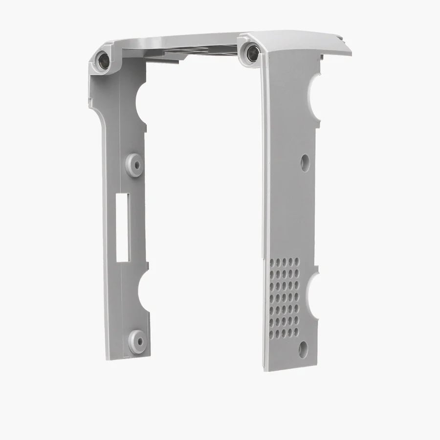
Toolhead Middle Housing
¶ Tools
- H1.5 hex key
¶ Preparation
Please ensure that you have unloaded the filament and powered off the printer before proceeding with the replacement.
¶ Disassembly
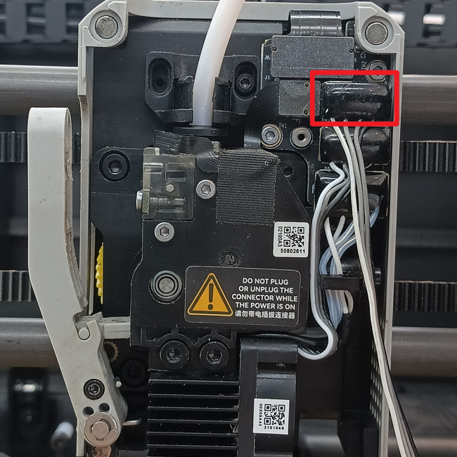
¶ Step 1 - Remove the Front Housing Assembly
Remove the Front Housing Assembly and disconnect the fan connector.
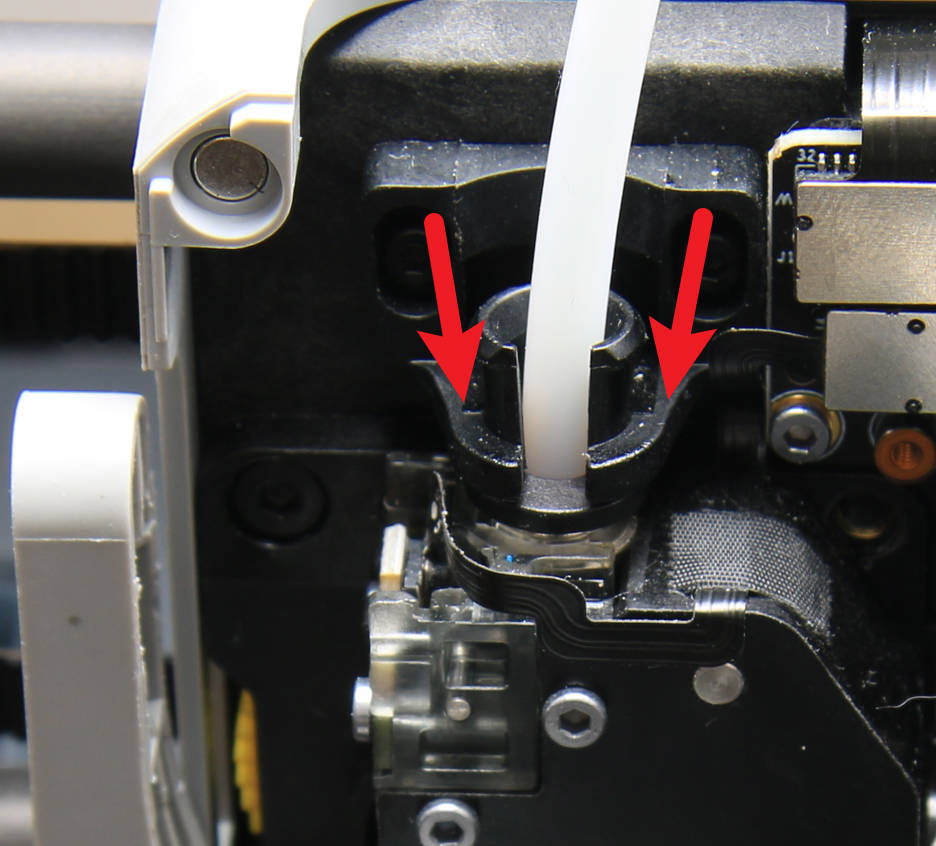
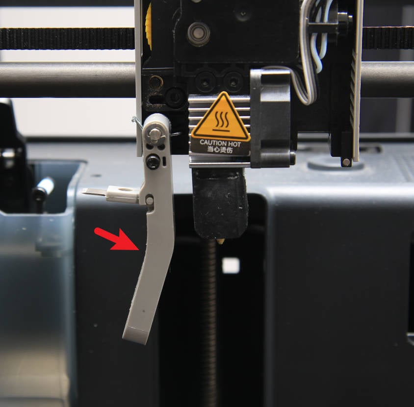
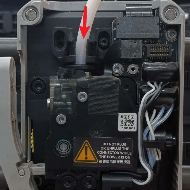
¶ Step 2 - Pull out the PTFE tube
Gently press the pneumatic joint and carefully pull out the filament tube, ensuring it is fully pressed down for effortless removal.
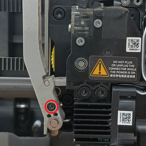
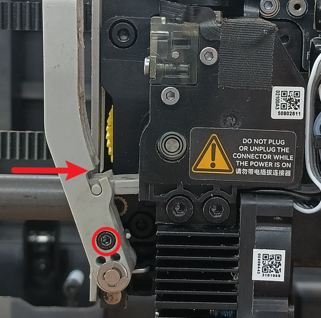
¶ Step 3 - Release the Filament Cutter Lever
Using an H1.5 hex key, partially loosen the screw on the cutter lever without completely removing it.
 |
 |
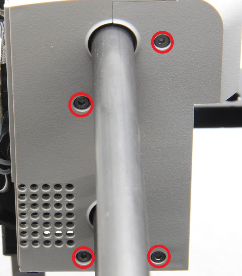
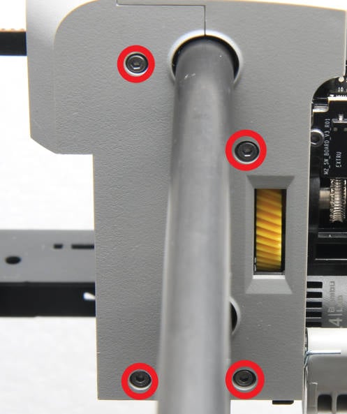
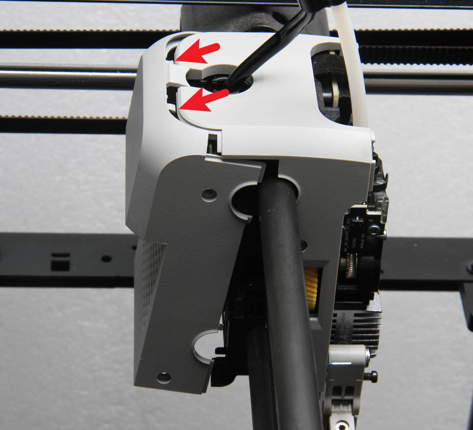
¶ Step 4 - Remove screws
Remove the 8 screws located on the sides of the tool head, with 4 screws on each side.
 |
 |
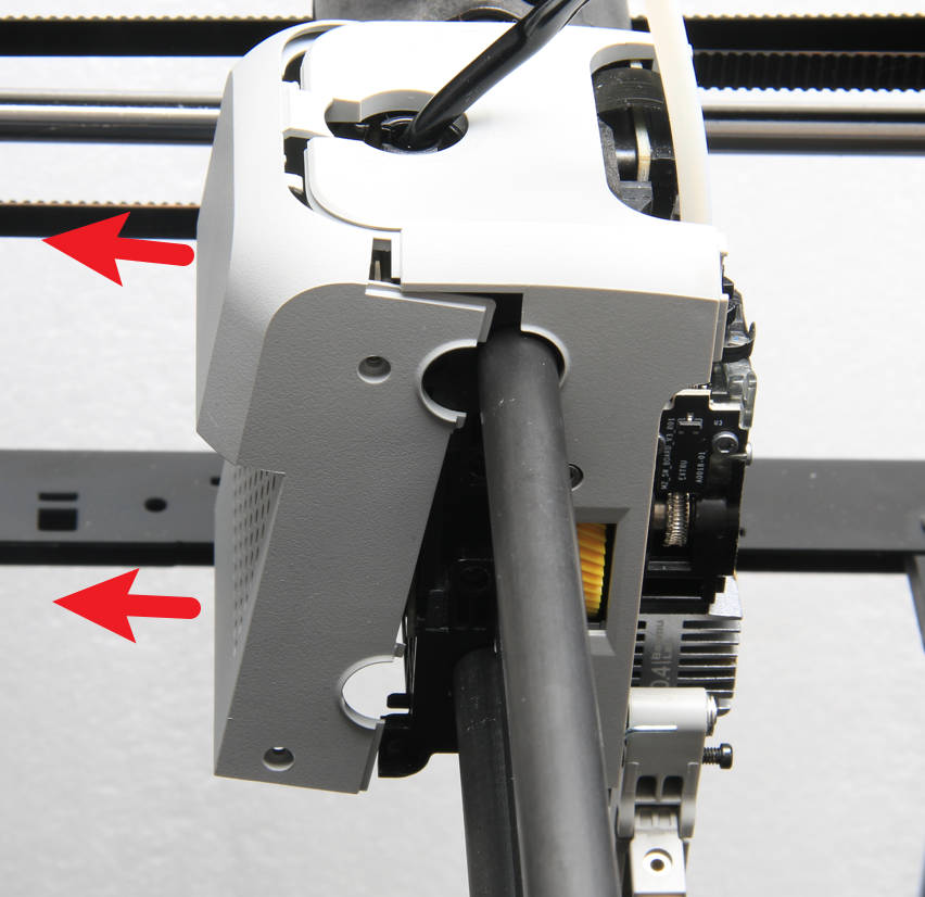
¶ Step 5 - Remove the Toolhead Rear Housing
Separate and remove the Toolhead Rear Housing from the Toolhead Middle Housing.
¶ Step 6 - Remove the Toolhead Middle Housing
Carefully remove the Toolhead Middle Housing while remaining cautious of the protruding cutter blade.
¶ Assembly
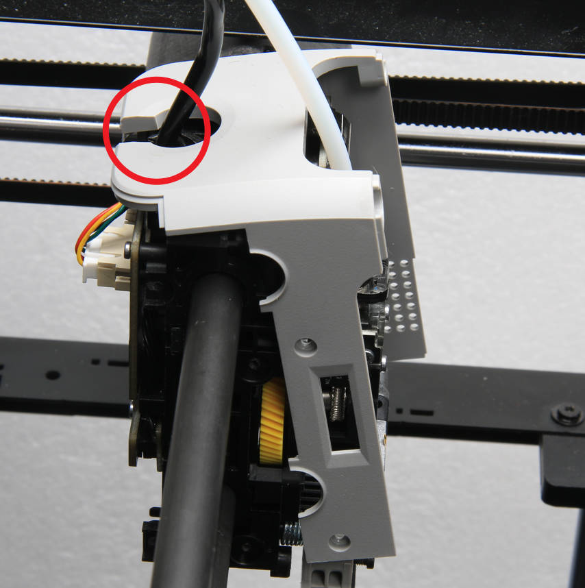
¶ Step 1 - Install the Toolhead Middle Housing
Install the Toolhead Rear Housing, aligning the position with the cable hole, as shown in the image below.
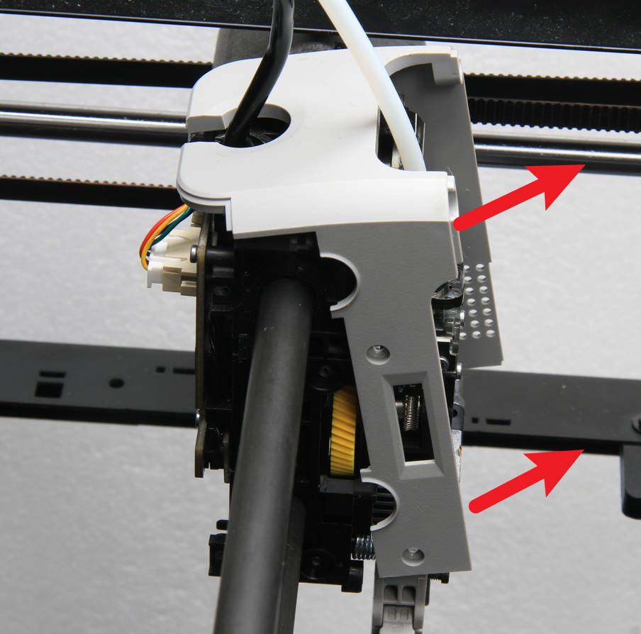
¶ Step 2 - Install the Toolhead Rear Housing
Install the Toolhead Rear Housing ensuring the clips are properly seated with the Toolhead Middle Housing.
¶ Step 3 - Lock screws
Once you have confirmed that the rear and middle housings are properly aligned and flush, you can proceed to replace the screws and tighten them securely.
|
|
|
¶ Step 4 - Install the Filament Cutter Lever
Using your hand, lift the Filament Cutter Lever and carefully slide the cutter blade into the designated slot within the extruder. Next, tighten the screw on the Filament Cutter Lever to secure it in place.
¶ Step 5 - Connect the tube
Insert the filament tube into the pneumatic joint securely and confirm its proper insertion by gently tugging on the PTFE tube.
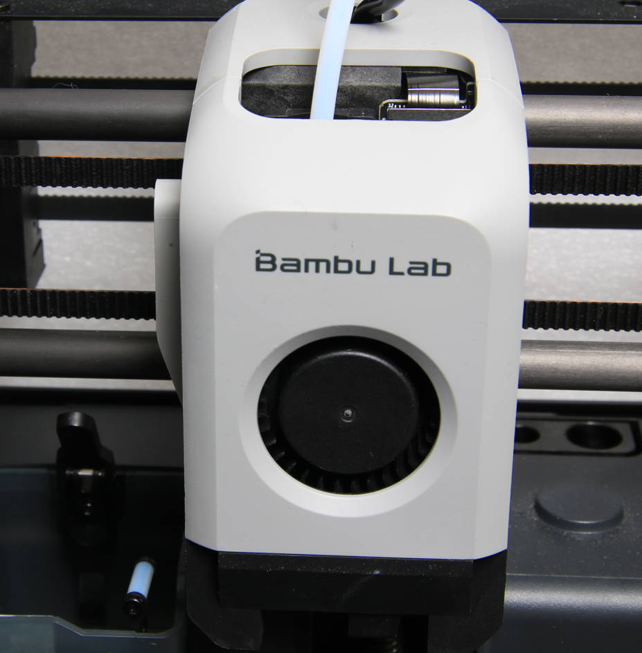
¶ Step 6 - Install the Front Housing Assembly
Connect the fan connector to the board and close the Front Housing Assembly.
For the X1 Series, please refer to Replace the Front Housing Assembly - X1 Series.
For the P1 Series, please refer to the following step.
 |
 |
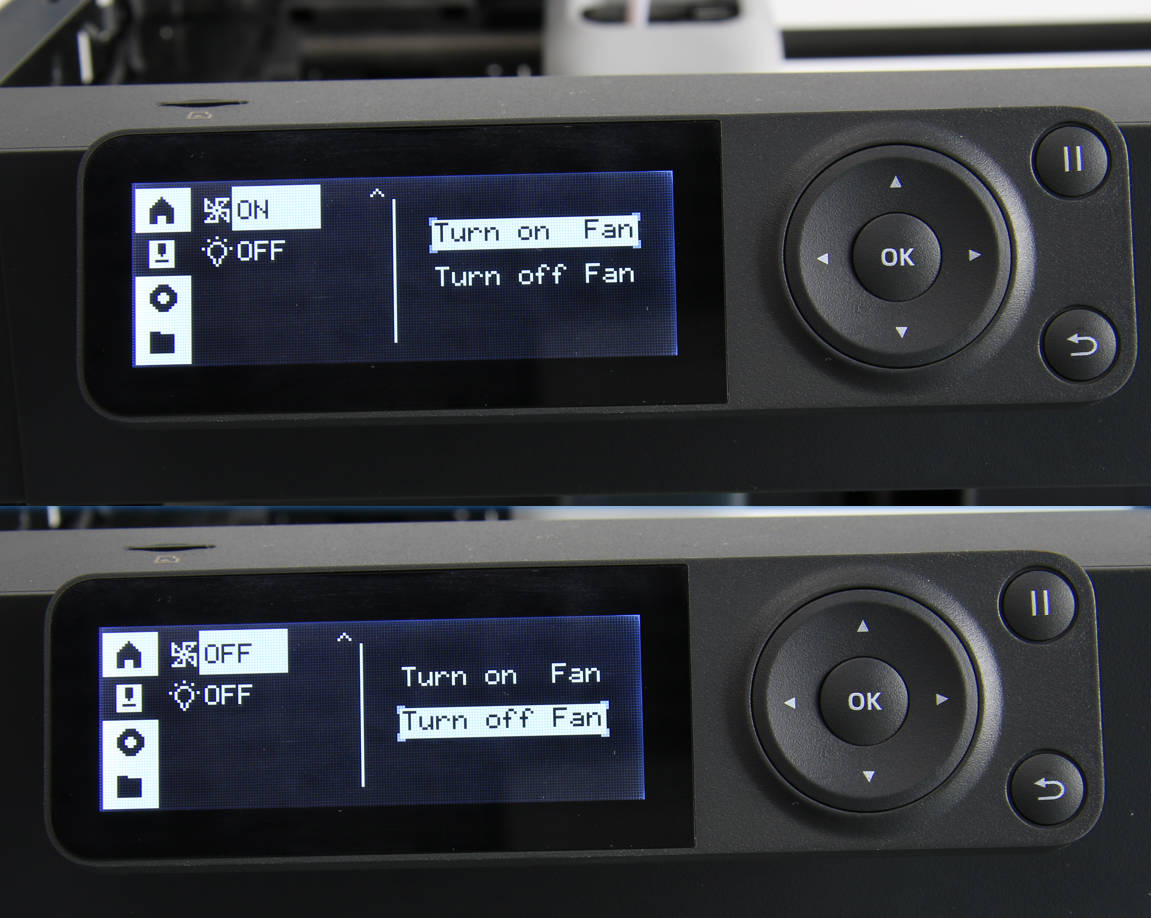
¶ How to verify
1. Perform a visual inspection to check the appearance of the printer. Ensure that the casing is flush without any misalignments or protrusions.
2. Power on the printer and access the screen menu. Manually toggle the cooling fan on and off to confirm its normal operation.