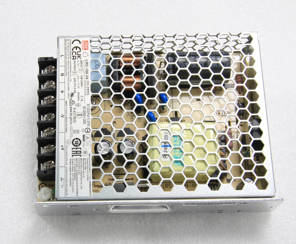
¶ Power module
¶ Tools
H2.0/1.5 hex key
Cross screwdriver
¶ Update and revision
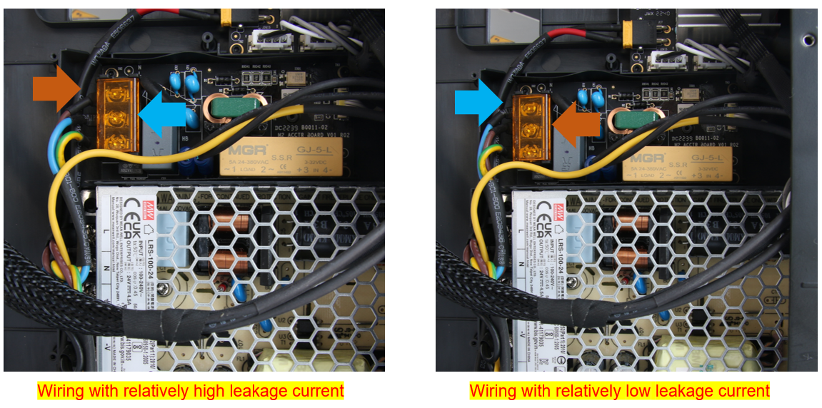
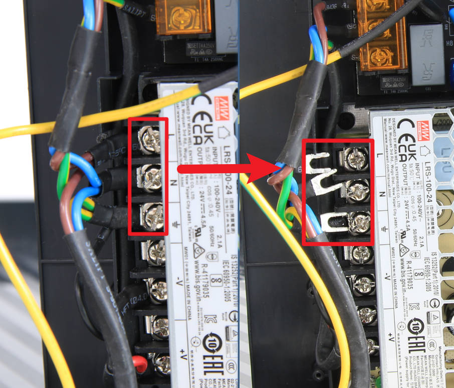
The subsequent figures in this article depict a wiring method with a relatively high leakage current, which is not the optimal approach. It is strongly recommended that you use the wiring method on the right, which has a low leakage current, instead of referencing the technique on the left.
¶ Preparation
Disconnect the power cord cable
¶ Disassembly
¶ Step 1 - Remove the rear panel, excess chute, and the cable cover
Refer to the related contents of the Cable cover to remove the rear panel, excess chute, and cable cover.
¶ Step 2 - Disconnect the power cable
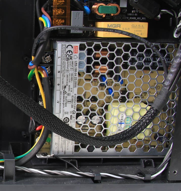
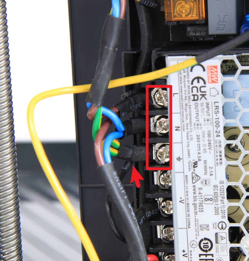
To release the 3 input cables, use a cross screwdriver to loosen the 3 crimping screws that hold them in place. Once the screws are loosened, the cables should be free to be removed.
¶ Step 3 - Disconnect the MC board power cable
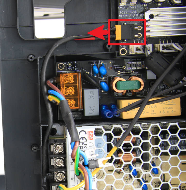
Disconnect the XT30 power cable from the MC board.
¶ Step 4 - Remove the power module
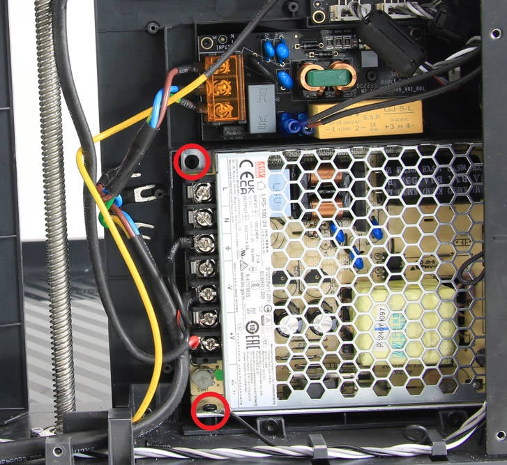
To remove the power module, use a hex key to loosen and remove the two screws that hold it in place. Once the screws are removed, the power module should be free to be lifted out.
¶ Step 5 - Remove the XT30 power cable
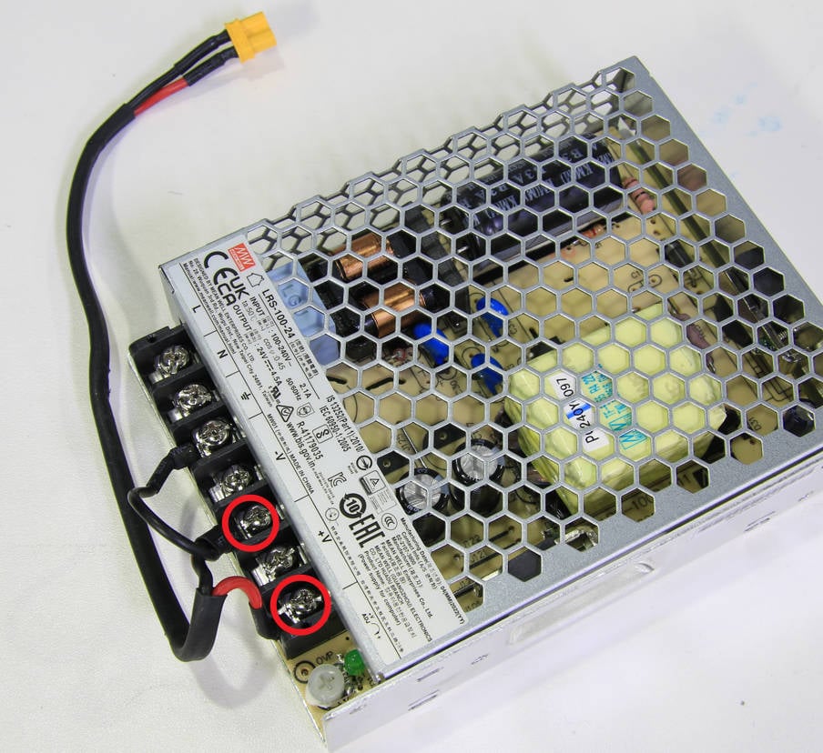
Use a cross screwdriver to loosen the two screws that hold the XT30 power cable in place. Once the screws are loosened, the XT30 power cable should be free to be removed.
¶ Assembly
¶ Step 1 - Install the XT30 power cable
Connect the XT30 power cable to the corresponding terminal, as shown in the picture below, and tighten the 2 screws (the ground cable screw does not need to be locked temporarily).
¶ Step 2 - Install the power module
Install the power module on the inner sheld, lock in 2 screws, a ground cable should be locked with the lower screws.

¶ Step 3 - Connect the XT30 power cable
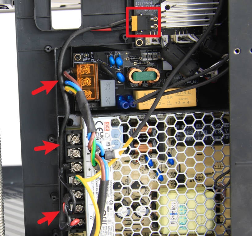
Route the XT30 power cable along the cable slot, then connect it to the MC board, and make sure it is inserted into the bottom.
¶ Step 4 - Connect the power cable
Insert the 2 power wires and 1 ground wire into the corresponding terminals, and tighten the screws in sequence. Be careful not to miss the ground wire of the XT30 power cord.

¶ Step 5 - Assemble the printer
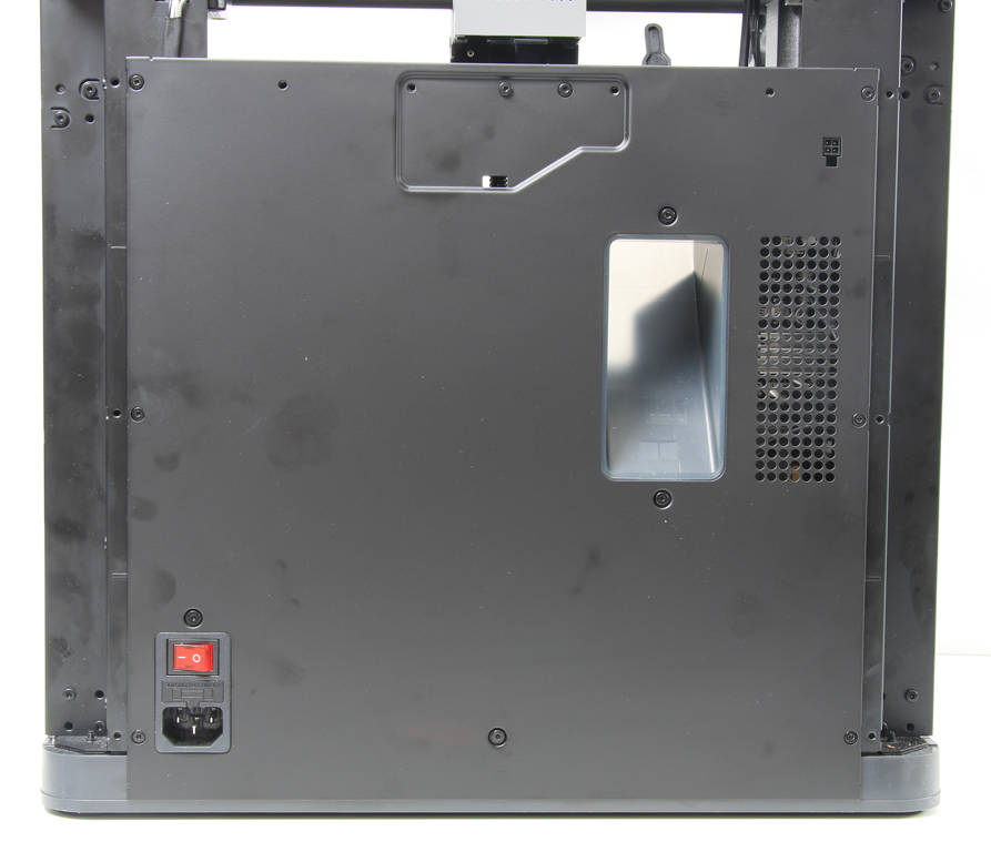
After arranging the cables, refer to the related content of the Cable cover to install the cable cover, the excess chute, and the rear plate in sequence.
¶ How to verify
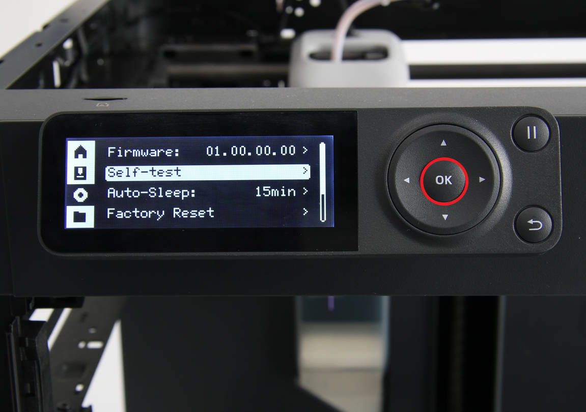
Connect the power cord cable of the printer, turn on the printer, and run the device self-test process. If the self-test passes, the operation is successful.
