¶ Why do we need the prime tower?
In 3D printing, we usually need a prime tower in multi-color printing tasks or when the smooth mode time-lapse is enabled. After the tool head travels or purging the filament, some residual material may still be left on the nozzle. Enabling the prime tower can clean up the residue on the nozzle and stabilize the chamber pressure inside the nozzle, to avoid appearance defects when printing objects.
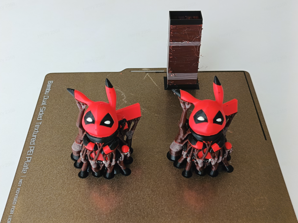
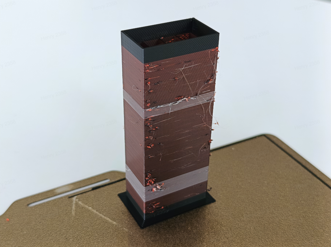
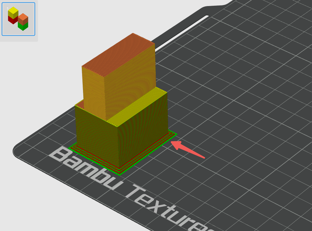
From the figure below, we can see that the surface of the prime tower absorbs a lot of defects, and it can help the surface of the printed model be more clean and tidy:
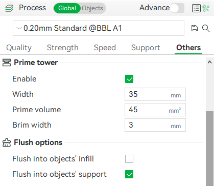
The prime tower is enabled by default but will only be generated on the build plate for multi-color printing tasks or when smooth mode time-lapse is selected. You can enable or disable it in Process —— Other —— Prime tower.
¶ Prime tower for multi-color printing
The explanation of the shape and parameters of the prime tower for multi-color printing is as follows.
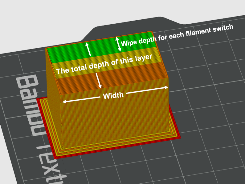
Width: The width of the tower can be customized by the user so that all tower layers use the set width.
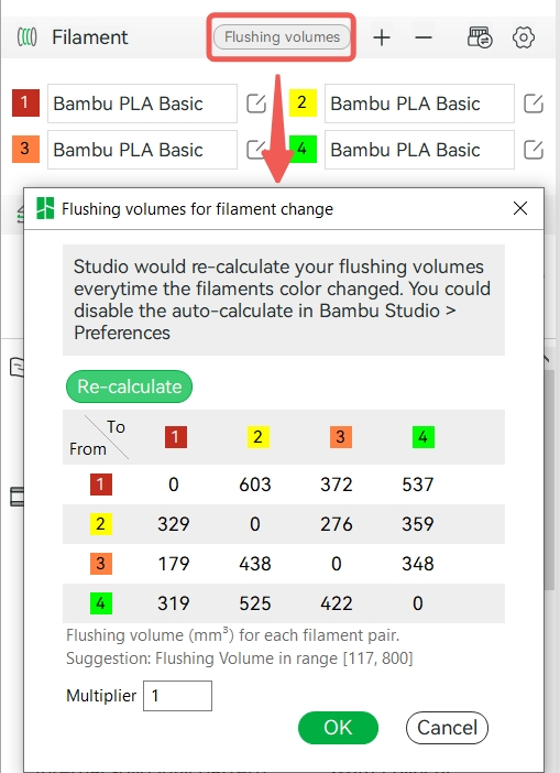
Prime volume: Represents the volume printed on the tower for each filament switch. This refers to the wiping volume on the prime tower, which differs from the flushing volume set when changing the filament.
Note: Flushing volume = The volume of flushing in the excess chute + The volume of flushing into support/infill/objects.
In each filament change, the length of printing on the tower can be calculated according to the set prime volume, layer height, and line width.
The number of turns = the length to be printed for each filament change/the width of the prime tower, indicating how many times it needs to be turned back and forth on the prime tower during the filament change, recorded as the number of turns.
Tower depth for each filament change = the number of turns * line width.
The total depth of the single-layer tower = (number of turns * line width) * number of filament changes in this layer.
Therefore, the more times a single layer changes the filament, or the greater the total prime volume amount, the greater the depth of the tower of this layer. However, if the total wiping volume of this layer is small, there will be a minimum depth limit at the bottom of the tower to prevent the tower from being too narrow and falling off during printing. When the prime volume is less, the tower still needs to ensure a certain depth, so the lines of the nozzle turning back on the tower will be sparse, rather than densely arranged. As shown in the GIF below:
If the amount of wiping amount required between different layers is different, and the calculated lower layer tower depth is smaller than the higher layer, the lower layer tower depth will be forced to be equal to the higher layer.
If the calculation shows that the higher layer tower depth is less than the lower layer tower depth, the tower depth of the higher layers is reduced and then centered as much as possible.
The height of the prime tower: The height of the prime tower is increased in sync with the objects, and the height of the tower for multi-color printing will stay in the last layer of color change. As shown in the following GIF, after the last color change, since the subsequent printing does not need to switch the filament, there is no need to wipe the nozzle in the prime tower. Some objects may need to change colors at a very high height, and the prime tower will print from the first layer until the layer that last color changes.
Brim width: It is used to set the width of the brim at the bottom of the wiping tower. Adding a brim can make the prime tower more stable and prevent it from falling off during printing.
¶ Prime tower for time-lapse
In addition to multi-color printing, the prime tower is also used for time-lapse photography. If you enable time-lapse in smooth mode, after printing each layer, the tool head will move to the excess chute and then take a snapshot. Since the melted filament in smooth mode may leak out of the nozzle when taking snapshots, it is also necessary to use the prime tower for nozzle wiping. When "Smooth Mode" is selected in time-lapse photography, a prime tower is generated on the build plate. So, in this way, it can also generate a prime tower for single-color printing tasks. You can refer to the wiki for details about time-lapse: Timelapse Functionality Introduction | Bambu Lab Wiki
However, suppose the current print task is already a multi-color print task. In that case, the smooth mode time-lapse photography will reuse the multi-color prime tower to wipe and will not generate an additional tower for time-lapse.
Width: Like the prime tower for multi-color printing, it is used to set the width of the tower, and the user can customize it so that all tower layers adopt the set width.
Prime volume: We cannot set the prime volume for time-lapse prime tower, it is only composed of two outer walls, the middle is hollow, and the depth is fixed.
The height of the prime tower: Since the principle of time-lapse is to take a snapshot after each layer is printed, the nozzle needs to be wiped on each layer, so the height of the time-lapse prime tower is equal to the highest object on the build plate.
¶ Matters needing attention
1. The prime tower before slicing is only a schematic diagram, and it does not represent the accuracy of shape, color, and height. The accurate shape, color distribution, and height can be previewed after slicing.
2. The prime tower only supports a unidirectional increase in Z height, so even if some layers do not switch filaments, the prime tower must be printed to ensure that it is consistent with the model height. It cannot be enabled in by-object printing mode.
¶ Bambu Studio 2.0 Prime Tower
Starting from Bambu Studio 2.0, we have added and optimized some Prime Tower settings, which are described as follows:
This article mainly introduces a series of optimizations of the prime tower in Bambu Studio 2.0.
¶ 1. Optimization of the prime volume parameter and the placement area
¶ 1.1 Position adjustment of the prime volume parameter
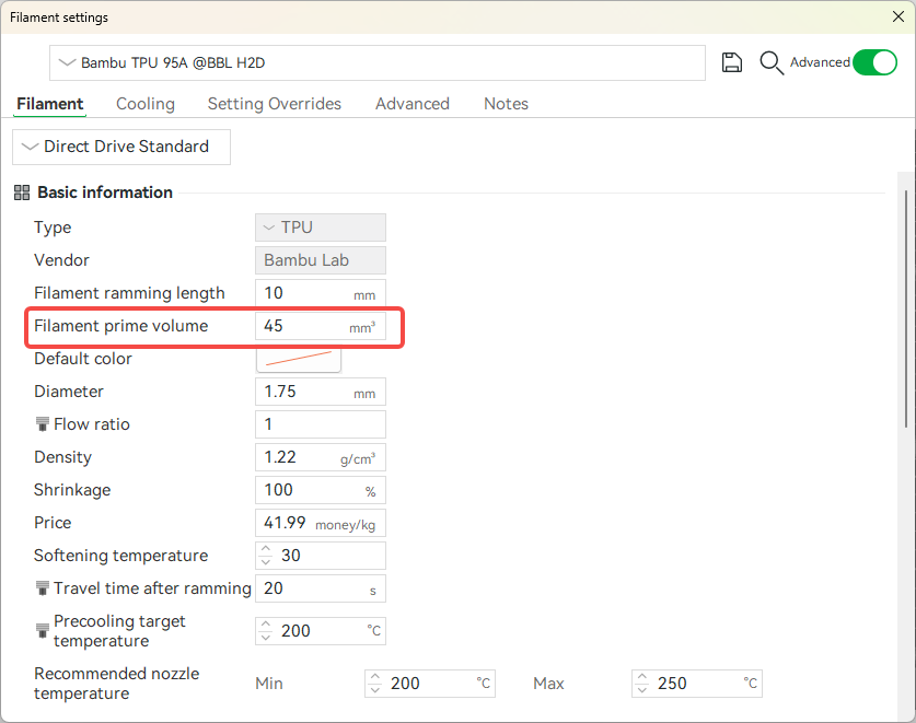
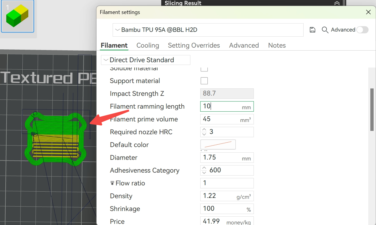
In Bambu Studio 2.0, we moved the parameter setting of the prime volume of the prime tower to the "Filament settings". This change allows users to set the prime volume for each filament separately when printing with multiple filaments, and no longer be restricted to the unified prime parameters.
¶ 1.2 Optimization of the prime tower placement area
Before slicing, the prime tower is only displayed as a schematic diagram. Its actual shape, height and color distribution can only be accurately previewed after slicing. To ensure that the prime tower does not exceed the boundary in most cases, we set a moving boundary limit for it before slicing.
From Bambu Studio 2.0:
-
After slicing, the system will update the shape of the prime tower in the preparation page based on the actual size;
-
Remove the original boundary limit, allowing users to freely adjust the position of the prime tower on the preparation page, optimizing the flexibility of the print layout.
¶ 2. Prime tower grouping structure
Purpose: To solve the problem of poor stability and easy collapse of the printed prime tower due to the difference in adhesion of different filaments.
¶ 2.1 Intelligent grouping
The software automatically divides the internal area of the prime tower according to the adhesion of the filaments.
-
Filaments with good adhesion (such as PLA Basic and PLA Matte) share the same block and have good stability.
-
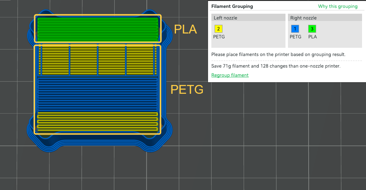
Filaments with poor adhesion (such as PLA and PETG) are printed in blocks, and physical isolation is used to avoid adhesion failure, as shown in the figure below.
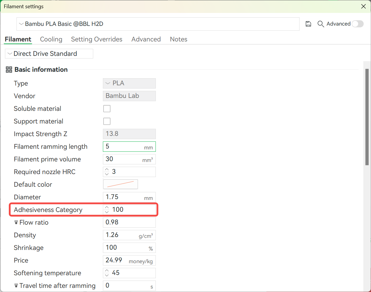
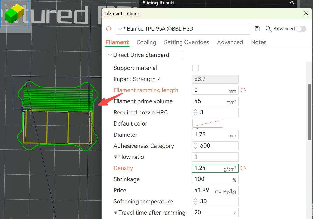
If you want to manually adjust the adhesion between filaments, you need to enter "Develop mode" first and change the Adhesiveness Category in the filament-related options. Filaments with the same value are considered to be firmly bonded to each other.
¶ 2.2 Automatic selection of outer wall filaments
The prime tower mainly relies on the outer wall to provide strength. The outer wall filaments are automatically composed of the filament group with the strongest adhesion. This is achieved through relevant planning algorithms. In special cases, additional replacement filaments may be required to ensure that the filaments that make up the outer wall of the prime tower are a group of filaments that are firmly bonded to each other. The software will first determine which filaments appear in the most layers. If a certain filament appears in most layers, it will be used as the outer wall of the prime tower. If multiple filaments appear in the same number of layers, the outer wall filaments will be selected from the smallest to the largest according to the adhesion category.
¶ 3. Optimization of the junction layer for filament switching
Problem background: Some models may only be printed with another filament with poor adhesion to it (such as support filament or other filament combination) after a certain height. This may cause the prime tower to be easily peeled off at the junction layer of different filament, so a transition layer is introduced here to optimize and improve this problem.
¶ 3.1 Adding a transition layer to the filament switching interface
Assuming that the filament is switched from the "nth" layer, the first 4 layers of the filament switching are used as transition layers, and the transition layers are printed with 100% filling.
-
Lower layer: Initially print a low-density support structure (also known as a skeleton) with the original filament (such as PLA) at the bottom of the prime tower to save filament. Until printing to 4 layers below the height of the switching filament (n-4 to n-1 layers), start printing the raw filament with 100% filling rate to form a stable base.
-
Upper layer: Print new filaments (such as support filaments) at 100% filling rate + low speed (20mm/s) at the switching layer (nth layer), print at low speed and full density coverage to enhance interface adhesion.
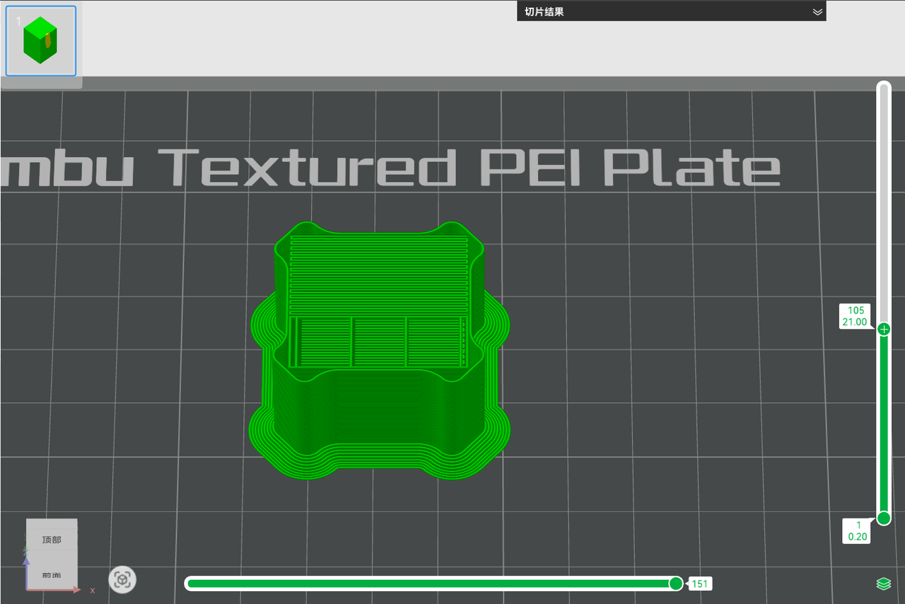
For example:
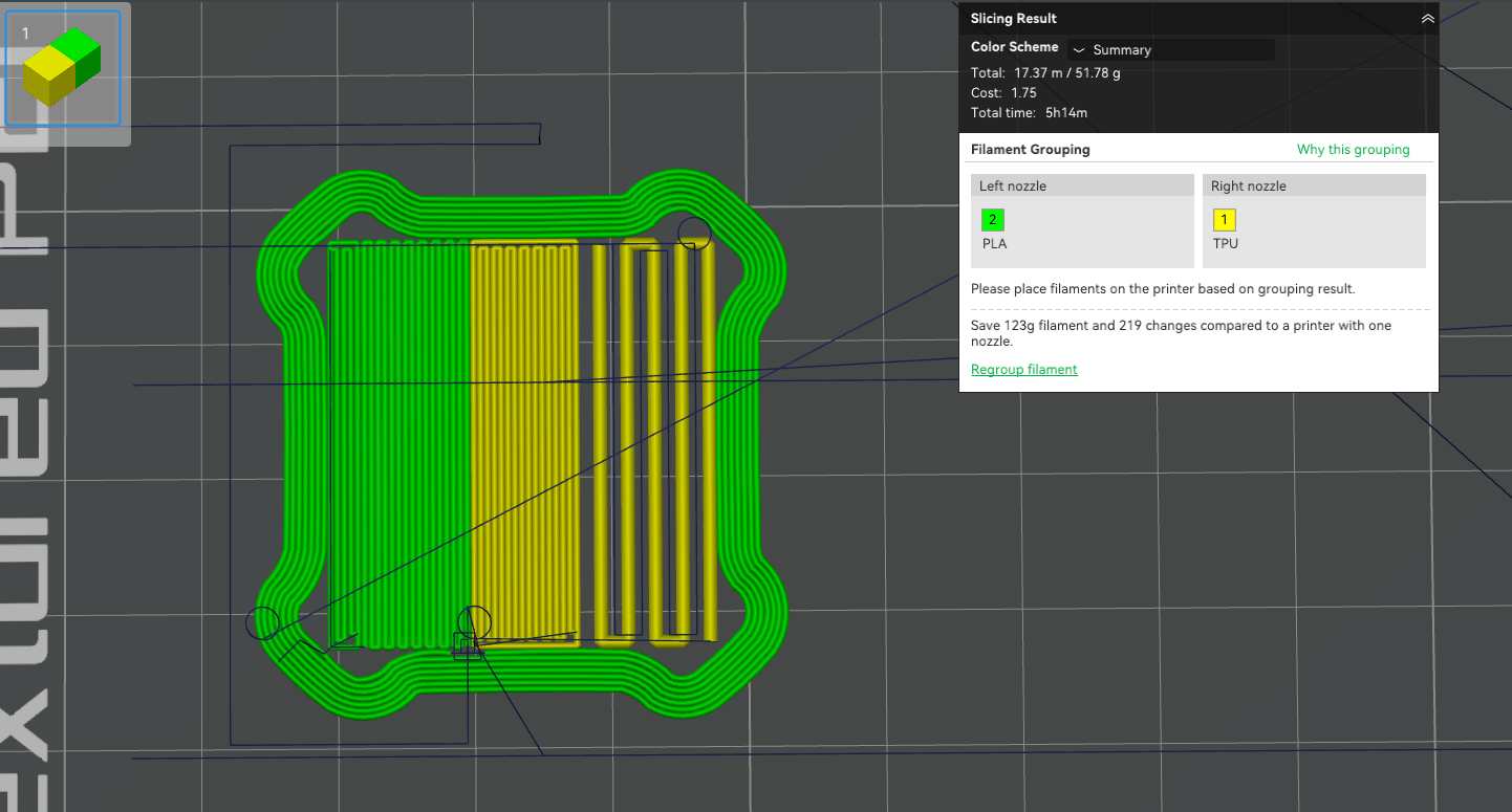
In the following PLA cube + TPU coating model case, the filament bonding strength is significantly improved by the transition layer, with the strength increased by 45%, avoiding the problem of the junction layer not sticking and causing it to fall off.
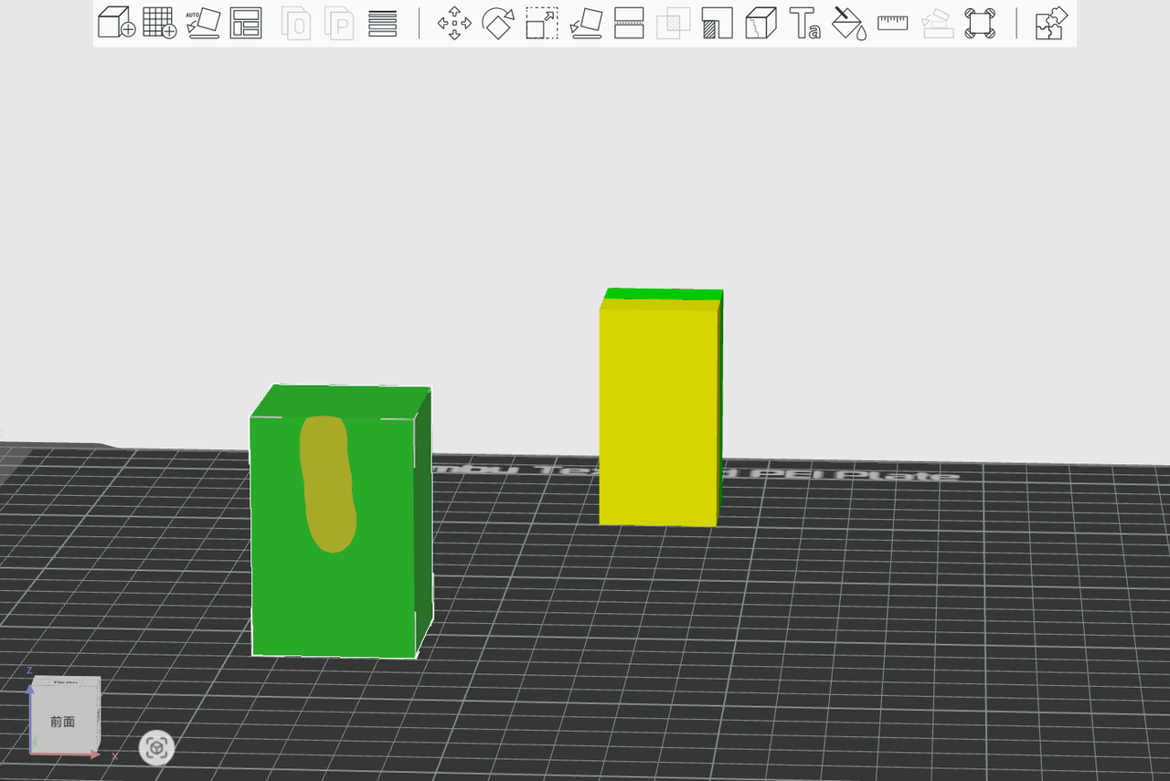 PLA+TPU model |
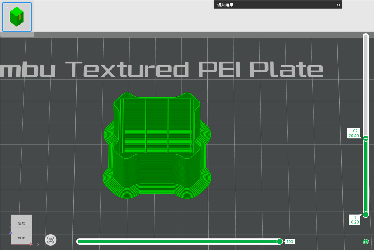 PLA skeleton layer |
 PLA transition lower layer, with 100% filling |
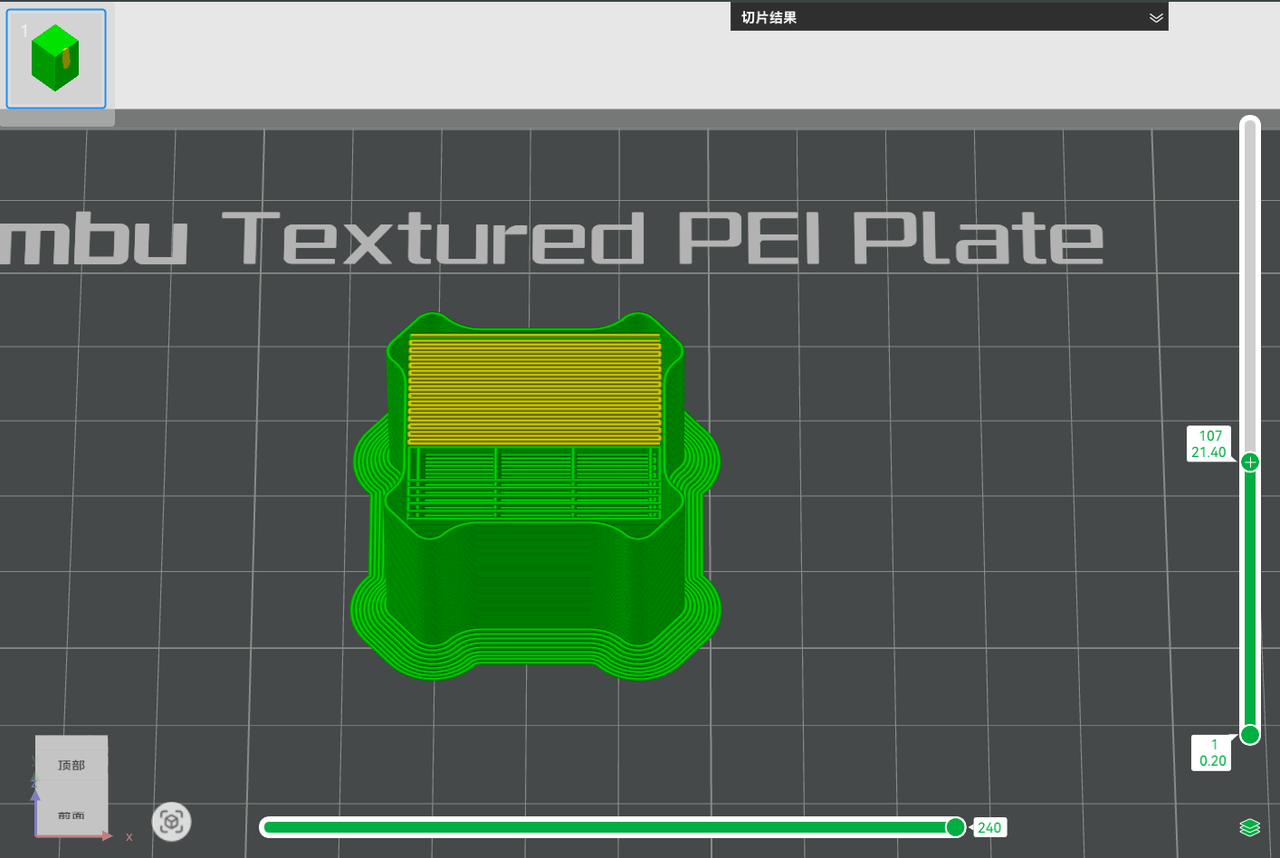 TPU transition upper layer, with 100% filling |
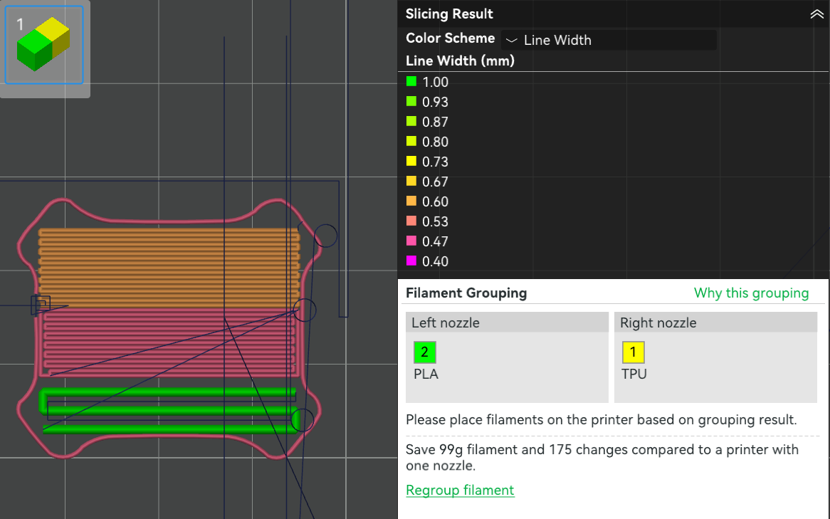
¶ 4. Multi-nozzle printing leakage control solution (only for multi-nozzle printers)
Before and after filament switching when using multi-nozzle printing, add extra idle movement for filament prone to leakage to reduce filament accumulation on the prime tower surface. When using multi-nozzle to print certain filaments with good fluidity (such as TPU), switch to another nozzle to continue printing. At this time, the nozzle corresponding to TPU will be suspended. In order to reduce leakage during the nozzle suspension period, the following measures will be introduced for optimization. Note: This part of the optimization is only for multi-nozzle printers.
¶ 4.1 Dynamic cooling control
For filaments with serious leakage, a section of filament will be quickly squeezed out on the prime tower before switching the nozzle, which is ramming. Cooling down while ramming can further shorten the time of travel adsorption (to be introduced in 4.2 below). This reduces oozing and stringing when switching nozzles without significantly increasing the filament switching time.
- Ramming length of filament: This parameter controls the length of the nozzle extruded on the prime tower before switching the nozzle, 0 means disabled. After disabling the ramming length of filament, only a simple support structure will be printed on the prime tower before switching the nozzle to provide support for the next layer, and there will be no more idle adsorption action, because the idle adsorption action is performed in the gap of filament ramming. Since ramming is printed at the maximum volume speed, the higher the volume speed, the less overflow. At the same time, in order to prevent the print speed from being too high, the line width of the ramming is twice the normal line width of the prime tower.
 Enable ramming |
 Disable ramming |
 The line width during the ramming is greater |
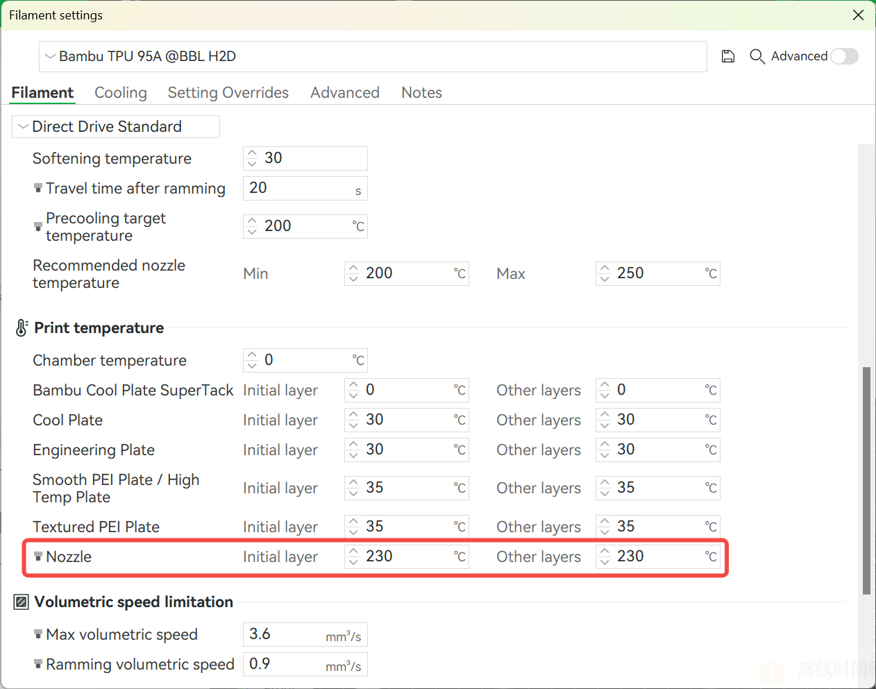
- Desired precooling temperature before switching nozzles: The target temperature for nozzle cooling during ramming.
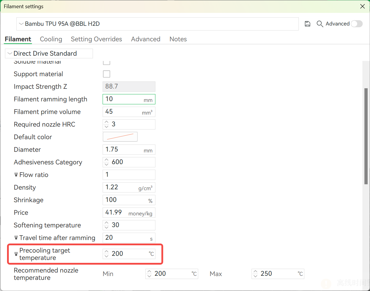
- Filament printing nozzle temperature
- Nozzle cooling rate: Determined by the printer model, users do not need to adjust it.
- Calculation formula:
Precooling time = (filament printing nozzle temperature - precooling target temperature) / nozzle cooling rate
- Execution logic:
-
Cooling is synchronized when quickly extruding on the prime tower before switching the nozzle.
-
The extrusion speed automatically adapts to the precooling time requirements.
-
Shutdown method: If you do not want to cool down in advance, set the precooling target temperature to 0℃ or greater than or equal to the nozzle printing temperature.
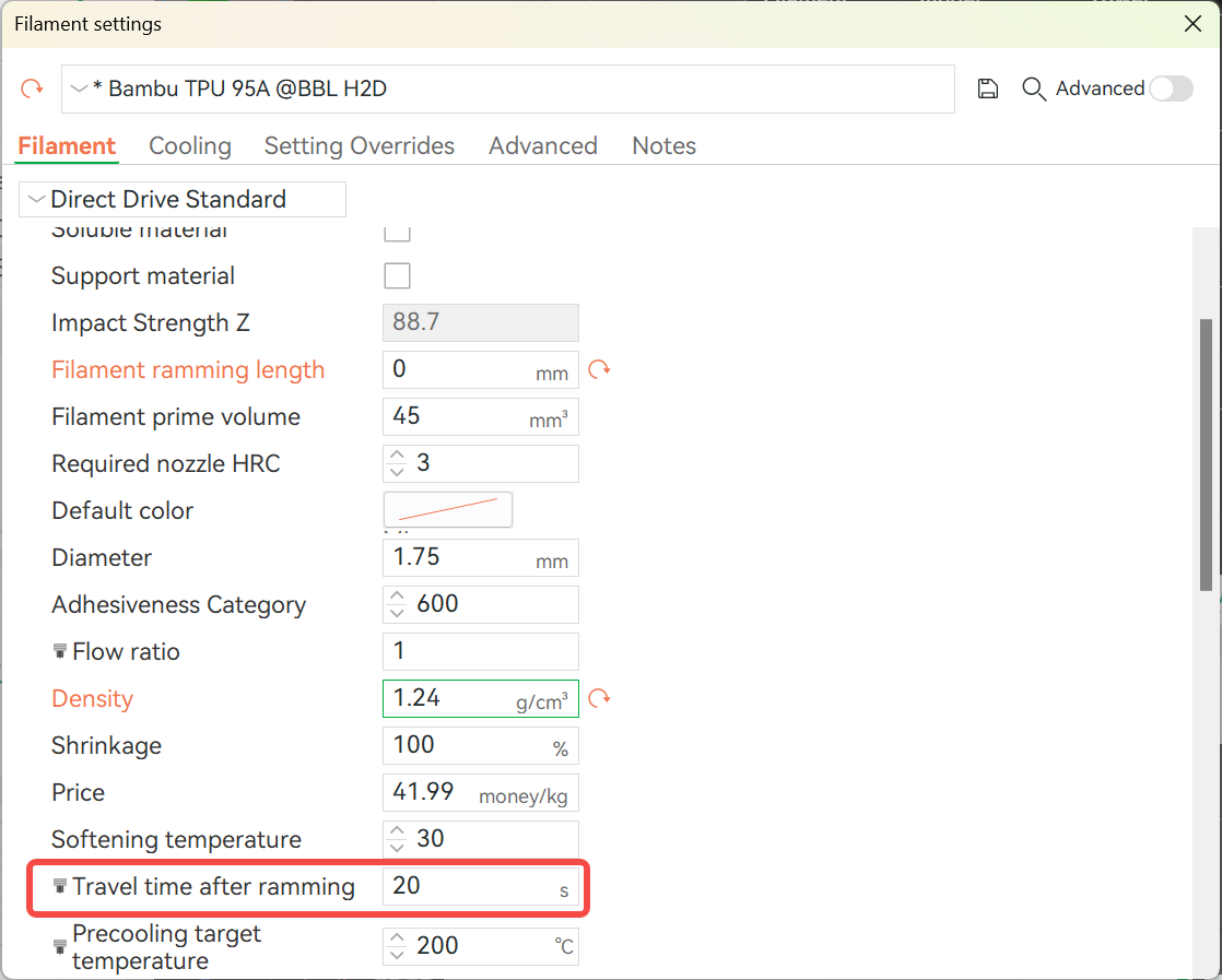
¶ 4.2 Travel adsorption before switching nozzles
- Operation logic: Before switching nozzles, the nozzle corresponding to the TPU executes an additional traveling path at the reserved adsorption gap of the prime tower to ensure that the molten filament is absorbed by the gap and does not remain on the printing path. Then it drives to the switching nozzle to perform the switching action. As shown in the figure below, the idle drive in the TPU routing gap travels before filament switching.
- Parameter control: You can customize the travel time after ramming in the filament settings (set it to 0s to turn off the travel time). In addition, if the travel time after ramming is set to be greater than 0, the ramming line spacing of the prime tower will be automatically set to 2 times the line width to leave space for the overflow of the travel.
¶ 5. Optimization of the starting point of the prime tower
Problem background: During the 3D printing process, a small amount of filament or overflowing waste (hereinafter collectively referred to as "filament end") is usually left after the nozzle is replaced. These filament ends may adhere to the surface of the prime tower, especially near the starting point. Once solidified, they will rub against the nozzle in subsequent printing, affecting the printing quality. To solve this problem, we have launched the following optimization solutions:
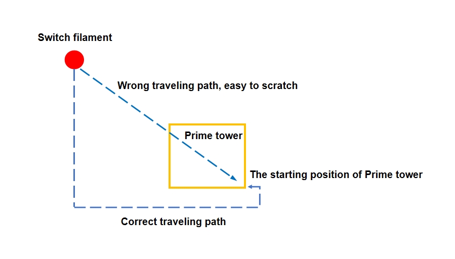
¶ 5.1 Prime tower travel avoidance
-
Problem background: After changing filaments, the empty traveling path passes through the main area of the wiping tower, and the leaked filament adheres to the filling area of the prime tower.
-
Solution:
The traveling path automatically bypasses the main body of the prime tower so that it no longer intersects with the prime tower outside its printing starting point, avoiding the filament end from sticking to the filling area of the prime tower, as shown in the figure below.
¶ 5.2 Add gaps in the outer wall
-
Problem background: The filament end sticks to the outer wall surface, destroying the consistency of the outer wall layer height, and the nozzle and the prime tower are easily scratched during subsequent printing, affecting the stability of the prime tower.
-
Solution:
-
Reserve a gap in the outer wall of the prime tower.
-
The first printing path after the filament switching enters from the gap, so that the filament end is attached to the gap of the outer wall instead of the outer wall surface.
- Operation options:
- Enabled by default, you can choose to enable or disable it in Bambu Studio: Process > Others > Prime Tower > Skip points.
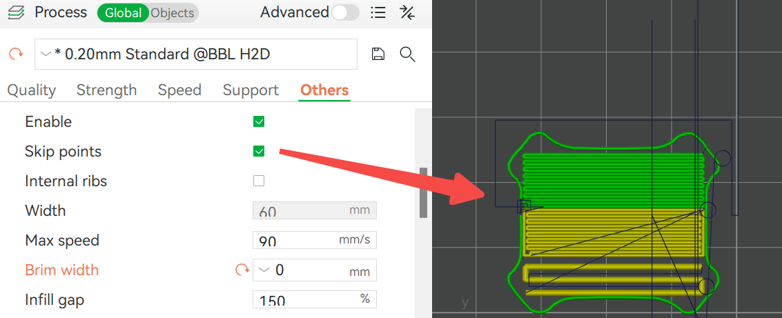 Enable skip points |
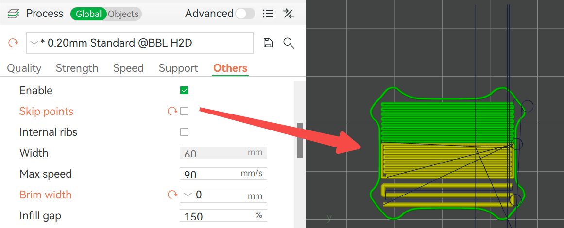 Disable skip points and print the closed outer wall |
¶ 5.3 Ironing at the start point of printing
In order to completely eliminate the influence of the filament end near the start point of the prime tower after filament replacement, the system will perform the "print-ironing-continue printing" operation at the start point of the prime tower. This process ensures the consistency of the layer height at the start point by compacting the filament, thereby significantly reducing the risk of scratching the nozzle and the prime tower in subsequent printing. The spiral travel in the figure below is the ironing action:
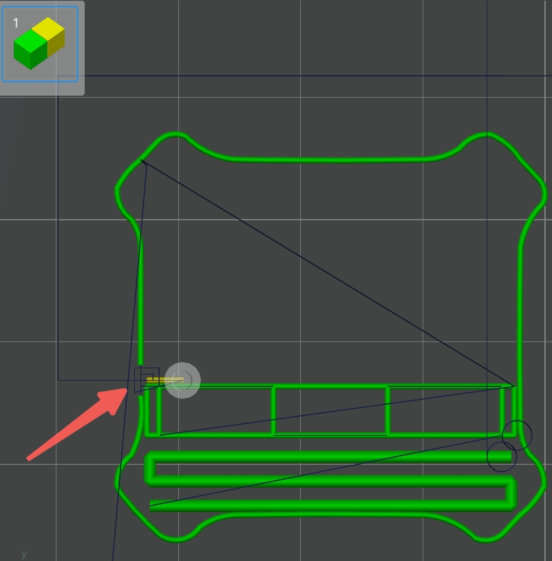
Operation options: This operation is linked to the skip points. Closing the skip points will disable this function.
¶ 6. Open additional parameter control
¶ 6.1 Prime tower internal ribs
During the printing process, since the number of times the prime tower needs to be changed may be different, the depth of each layer of the prime tower may be different, and "empty areas" may be formed inside the prime tower. The latest slicing algorithm of the software adds an internal rib structure. After enabling the internal ribs, the algorithm will generate a support structure in the original empty area, thereby significantly enhancing the overall stability of the prime tower.
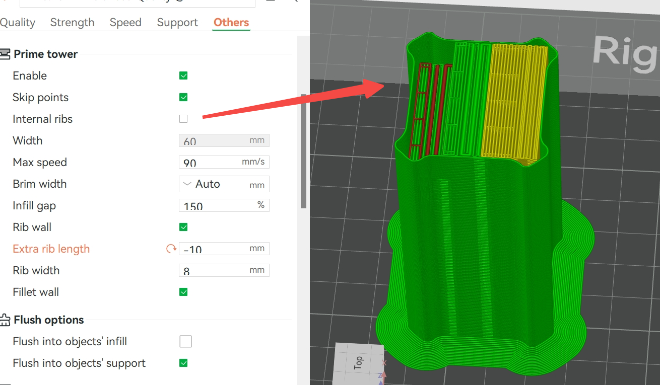 The upper prime tower is narrow and there is an empty space inside the tower. |
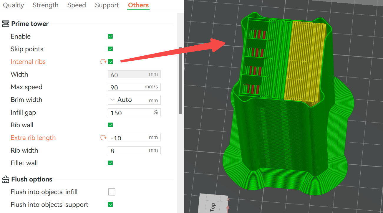 Use internal ribs to increase stability in empty areas |
¶ 6.2 Prime tower line infill gap
The line gap of the prime tower filling part can be manually set, as shown in the figure below. This parameter represents the spacing between the center lines of two lines. Properly increasing the infill gap can help reduce printing problems caused by filament expansion or accumulation.
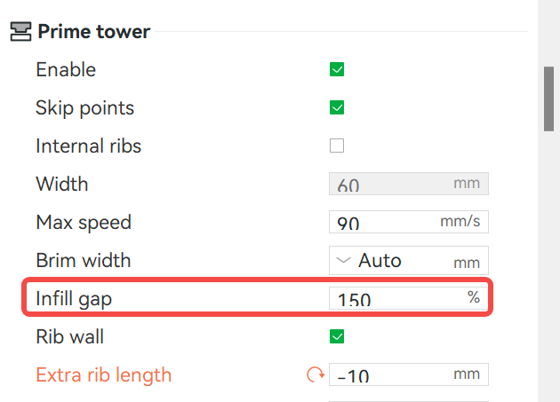
- Setting method:
-
The default value is 150%, that is, the distance between the center lines of the two traces is 1.5 times the line width, that is, the interval between the two traces is 0.5 times the line width.
-
hen set to 100%, the trace spacing will be 0, which is suitable for high-density filling requirements.
- Notes:
- If the filament ramming function before switching nozzles is enabled (see Section 4.1), the trace spacing of the ramming part will not be less than 200%.
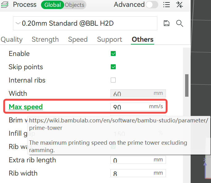
¶ 6.3 Print speed of prime tower filling
The max speed of the filling part of the prime tower supports custom settings, and the default value is 90mm/s. If you think the quality of the prime tower surface is better, you can increase it appropriately, but this will increase the risk of scratches between the toolhead and the prime tower.
¶ 7. Optimization of the outer contour of the prime tower
Traditional prime towers are mostly columnar or cubic structures. As the height increases, the following problems are prone to occur under the force of the nozzle:
-
Large Z-axis deformation: Further increasing the risk of scratching the nozzle and the prime tower.
-
Increased bottom bonding requirements: A greater heatbed bonding force is required, otherwise, it is easy to tilt or collapse.
-
Filament waste: Although simply increasing the size of the prime tower can alleviate the problem, it will lead to filament waste.
In the new version, we have significantly improved the overall structural strength and stability by optimizing the outer contour of the prime tower, making it more resistant to tilting when stacked high.
¶ 7.1 External reinforcement rib design
- Functional description:
Add oblique reinforcement ribs to the outer periphery of the prime tower to improve vibration resistance and impact resistance and reduce the deviation caused by nozzle scratches. We call this design "Rib prime tower", and its opening method and shape are shown in the figure below.
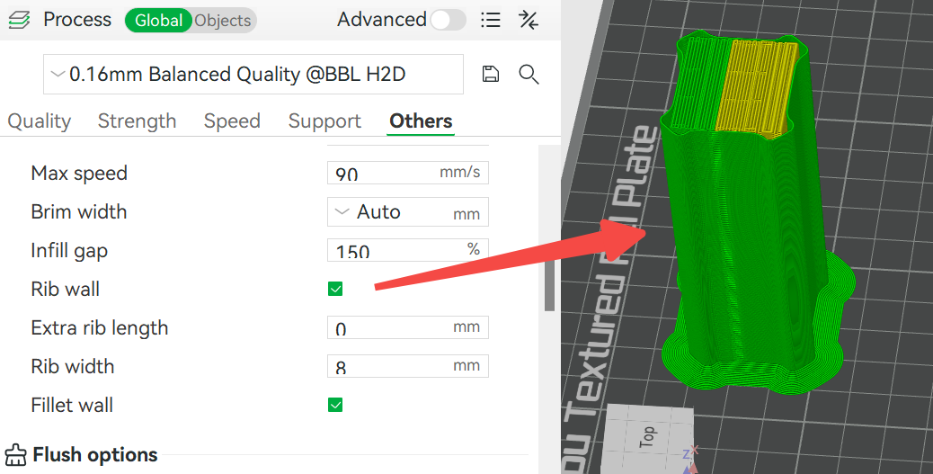 Enable rib wall |
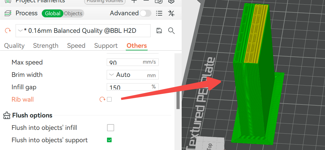 Disable rib wall, the traditional column structure |
- Advantages:
-
Compared with traditional equal-section columns, the rib wall design takes up less space and saves filaments.
-
Reduces Z-axis shaking and ensures the stability of the printing surface.
-
The non-rib part fits tightly with the filling structure to enhance the overall support strength.
Note: When the rib wall is enabled, the width of the prime tower cannot be adjusted to ensure that the shape of the prime tower is square.
- Parameter adjustment:
You can change the shape of the rib prime tower by adjusting a series of parameters, which are explained below.
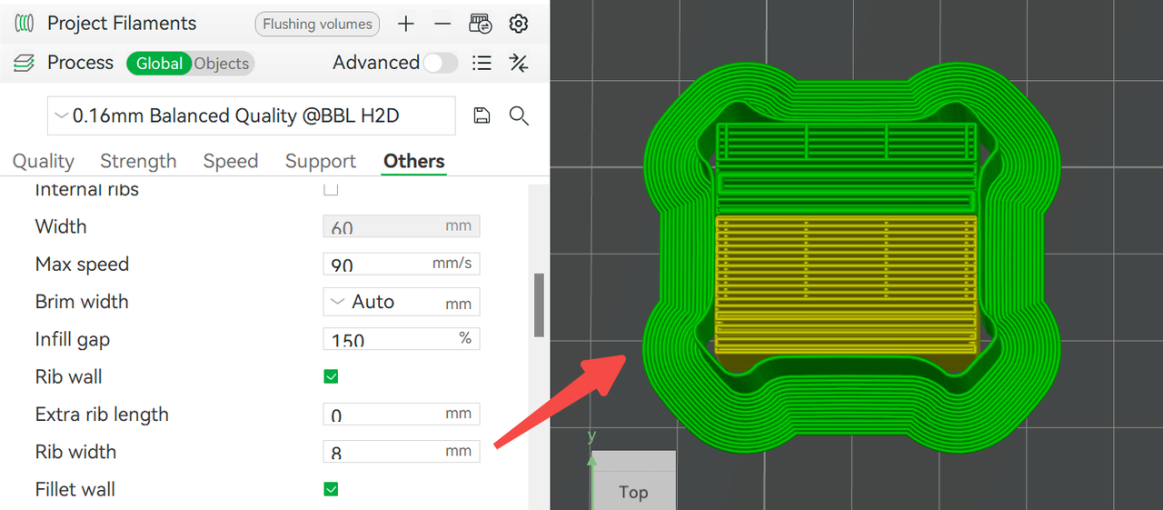
- Extra rib length: Used to add extra length to the ribs. The longer the extra length, the more space the prime tower will take up on the build plate.
 Default extra rib length |
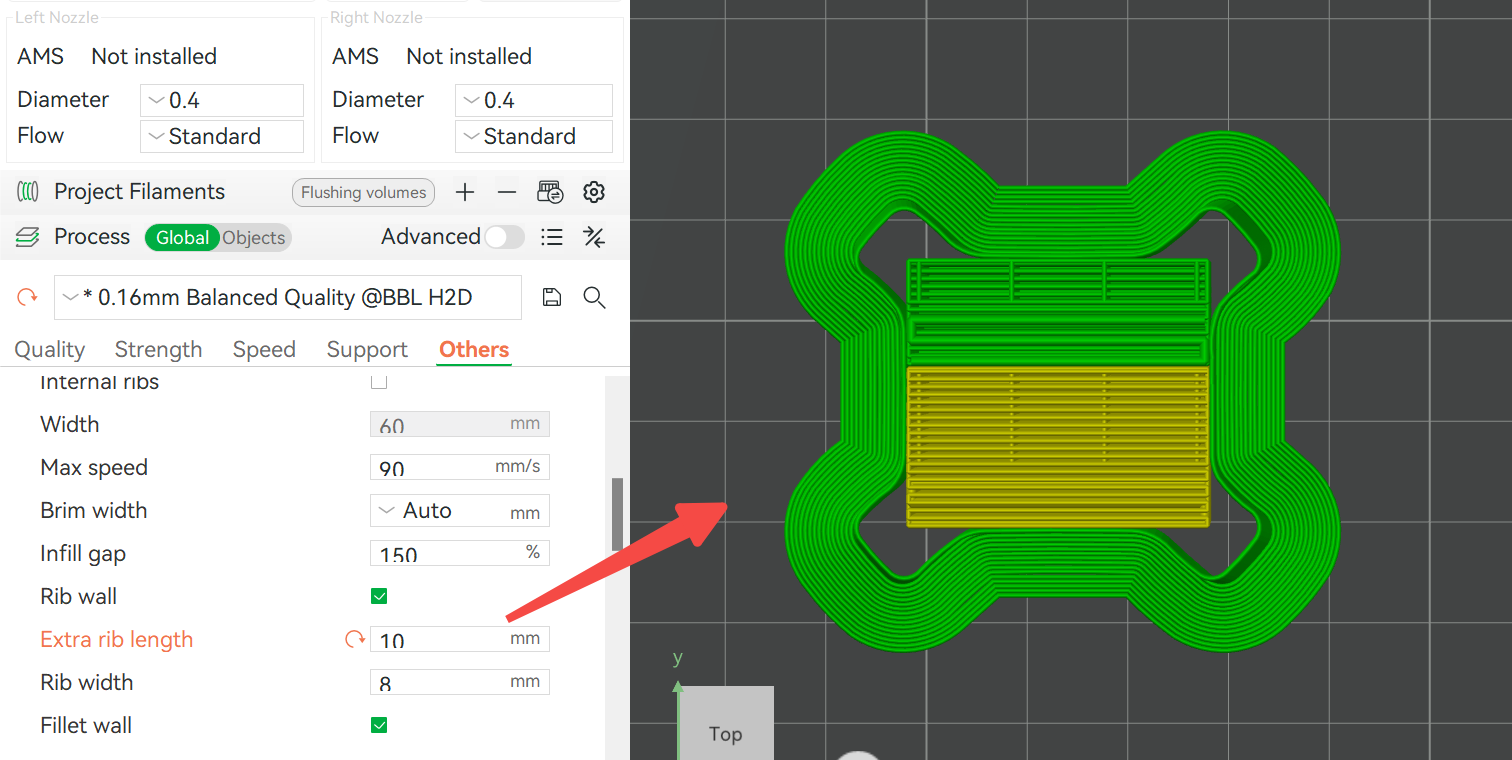 Extra rib length: 10mm |
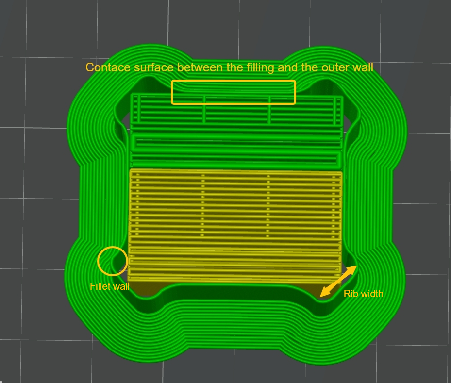
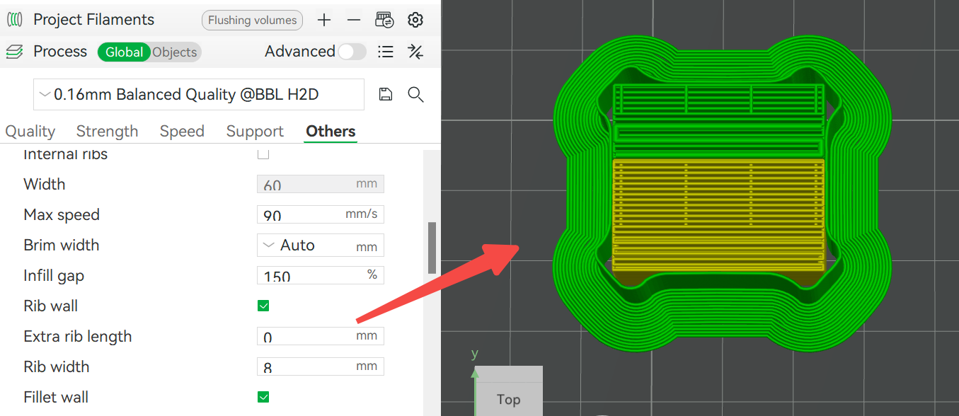
- Rib width: Used to control the rib width. Note: The rib width cannot be increased infinitely. It is necessary to ensure that there is enough contact area between the outer wall and the filling part to maintain the overall strength.
 Default rib width |
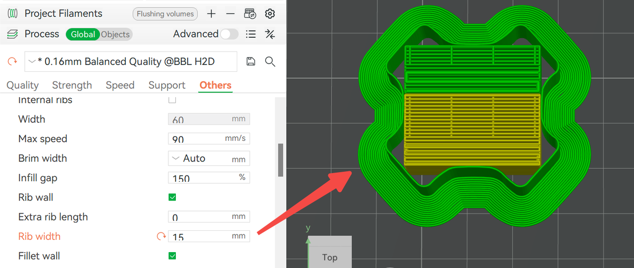 Increasing the rib width will reduce the contact area between the outer wall and the filling. |
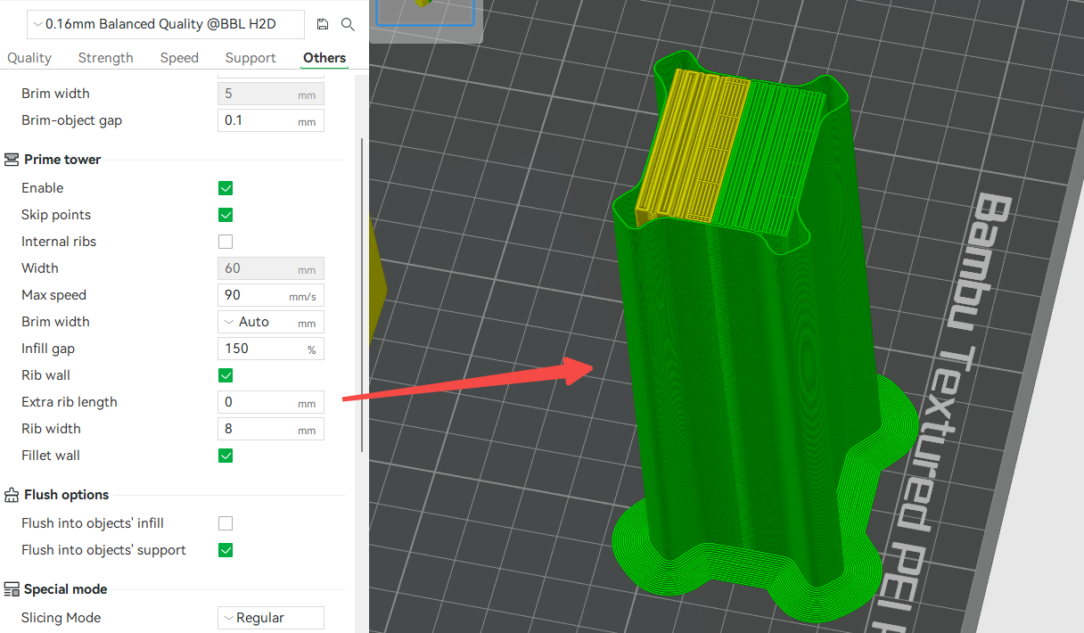
- Fillet wall: After enabling the fillet wall, the outer wall corners will transition in the form of rounded corners. The difference in the enabling effect is shown in the figure below.
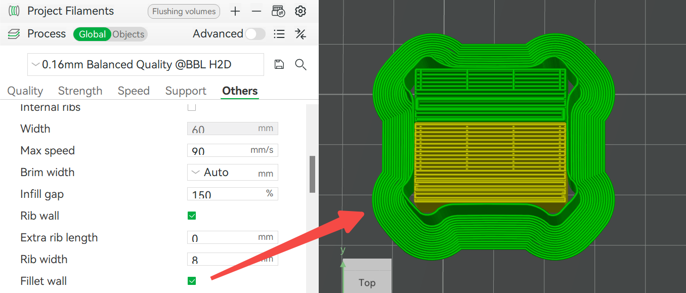 Enable fillet wall |
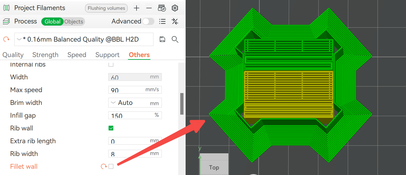 Disable fillet wall |
¶ 7.2 Dynamic profile adjustment
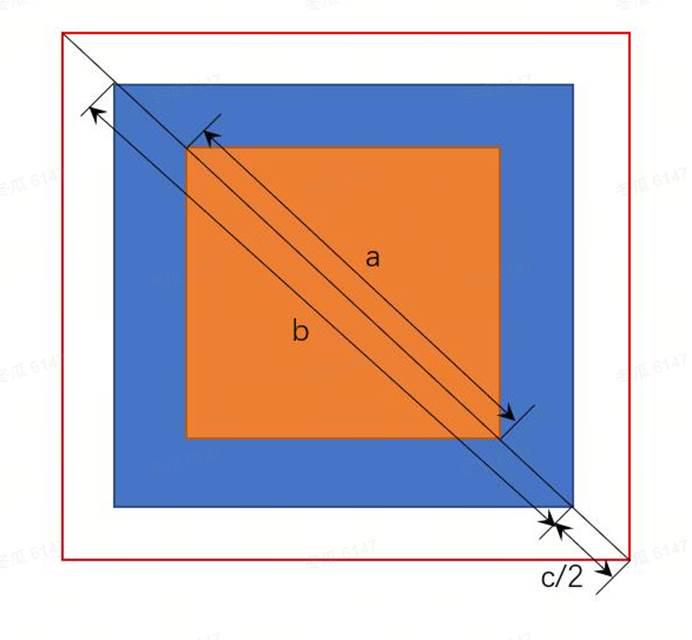
To ensure that the rib prime tower has consistent strength in the X and Y directions, we designed it to be close to a square shape and expressed its size by diagonal size. The specific size calculation is as follows:
-
Orange part (a): The minimum size that meets the prime volume requirements before and after filament switching, which can be adjusted by adjusting the filament punching length, filament prime volume and filling gap.
-
Blue part (b): The recommended size that meets the strength requirements of the prime tower, which is dynamically adjusted with the height and automatically calculated by the program.
-
User adjustment value (c): Allows users to make additional adjustments based on the recommended size. C is the extra rib length mentioned above. Its value can be positive or negative. Positive values increase the rib wall, and negative values reduce the rib wall. The rib wall size cannot be less than the minimum value determined by the prime volume. In the following example, when the prime tower is higher, its size is automatically adjusted to the size that meets the strength requirements. By reducing the additional length of the rib, it can be reduced to the minimum size that meets the prime volume requirements.
 |
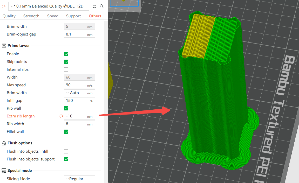 Negative value reduces the extra rib length |
So, the final size of the prime tower = max(b + c, a)
¶ End Notes
We hope the detailed guide provided has been helpful and informative.
If this guide does not solve your problem, please submit a technical ticket, we will answer your questions and provide assistance.
If you have any suggestions or feedback on this Wiki, please leave a message in the comment area. Thank you for your support and attention!